Применимость
| Модель | Двигатель | Год |
|---|---|---|
| XC90 | — | 2007–2015 |
Примечание: - Cable harness A for USB
- Cable harness B for iPod
- Cable harness C for USB and iPod
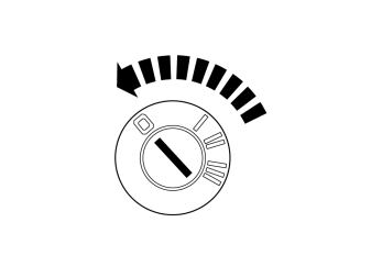
Applies to cars with external amplifier
- Slide the front seats back and upwards at the front edge.
- Turn the ignition key to position 0.
Примечание: Wait at least three minutes before unplugging the connectors or removing other electrical equipment.
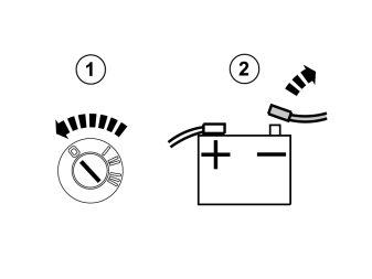
Applies to cars with internal amplifier
- Slide the front seats back and upwards at the front edge.
- Turn the ignition key to position 0.
- Disconnect the battery negative lead.
Примечание: Wait at least three minutes before unplugging the connectors or removing other electrical equipment.
Applies to all models
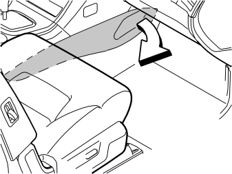
- Remove both the side panels from the tunnel console.
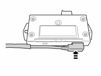
- Take the cable harness and control module from the kit. Connect the cable harness to the control module.
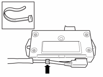
- Secure the cable harness to the control module using a cable tie.
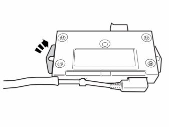
- Fold up the left mounting of the control module.
Примечание: Mirror steps 6-8 on right-hand drive cars.
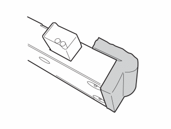
- Take a piece of foam tape from the kit and cut in the middle. Place a piece on the right-hand mounting of the control module.
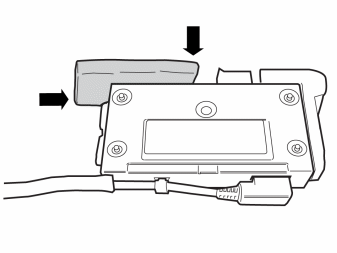
- Apply a piece of foam tape so that it covers half the upper edge and half the side edge.
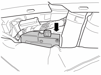
Applies to left-hand drive cars
- Push the carpet on the right-hand side of the tunnel console to one side.
- Place the control module between the carpet and insulation. The right-hand mounting of the control module should be below the air duct.
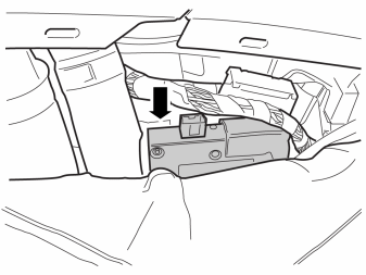
Applies to right-hand drive cars
- Push the carpet on the left-hand side of the tunnel console to one side.
- Place the control module between the carpet and insulation. The left-hand mounting of the control module should be below the air duct.
Steps 11 - 19 apply to vehicles with External amplifier
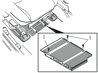
- Slacken off the amplifier screws (1) under the right-hand front seat.
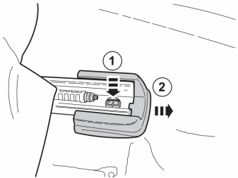
- Remove the left-hand seat piece.
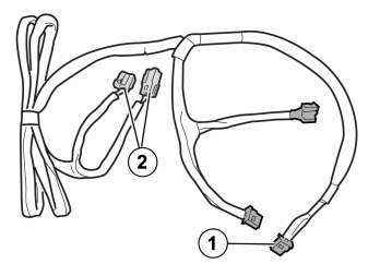
- Take cable harness (D) from the kit. Route the end of the cable harness with connectors 1 and 2 under the carpet, from the amplifier to the tunnel console.
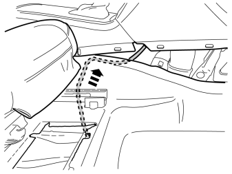
- Follow the existing cable harness.
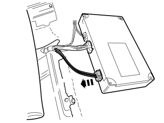
- Disconnect the connector on the amplifier.
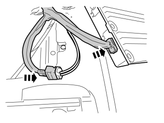
- Connect the connector that was disconnected from the amplifier to the connector on the new cable harness.
- Take a piece of foam tape from the kit and cut in the middle. Place a cut off piece of foam tape around the connectors.
- Connect the other connector to the amplifier.
- Reinstall the amplifier and the seat side piece.
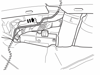
Applies to left-hand drive cars
- Route the two 4-pin connectors straight through the tunnel console.
Applies to right-hand drive cars
- Route the two 4-pin connectors straight forward at the side of the tunnel console.
- Route the connector with fiber optic cable straight through the tunnel console.
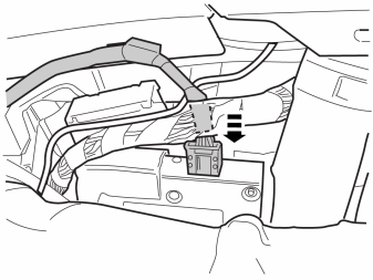
- Connect the connector to the control module.
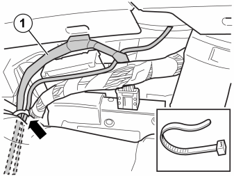
- Secure the three cables (fiber optic, power and USB/iPod cables) in the existing cable harness using a cable tie.
Примечание: Observe caution, the fiber optic cable (1) is sensitive to bending and trapping. The bend radius must not be less than 25 mm.
Steps 20-26 apply to cars with Internal amplifier
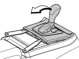
Applies to cars with automatic gearbox
- Turn the ignition key to position II.
Applies to all models
- Move the gear selector lever to its rearmost position.
- Use a weatherstrip and pry off the gear selector panel at the rear edge.
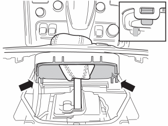
- Press in the catches and remove the panel.
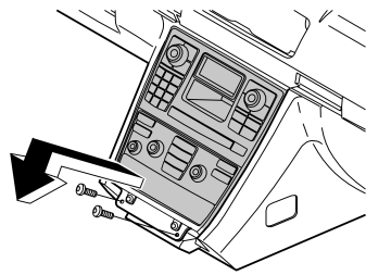
- Remove the two screws.
- Remove the audio/ ACC panel from the center console. Pull at the lower edge and then downwards until it releases from the mounting at the upper edge.
Примечание: Do not damage the removed components or the surrounding panels.
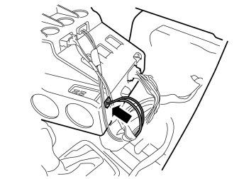
- Disconnect the connector for the fiber optic cable from the media player (IAM)
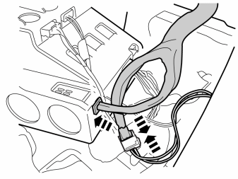
- Take cable harness (D) and a piece of foam tape from the kit. Cut off the foam tape in the middle.
- Connect the connector that was disconnected from the media player to the connector on the new cable harness.
- Tape one cut piece of foam tape around the connectors.
- Connect the other connector to the media player.
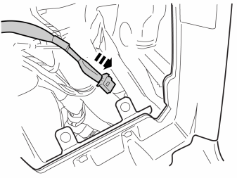
- Route the remaining connector down to the control module. Reinstall the audio/ACC panel.
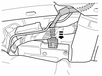
- Connect the connector to the control module.
Applies to all models
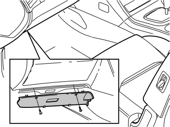
- Remove the sound barrier on the driver's side by first removing the two screws and then prizing it away at the top edge.
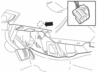
- Locate the 4-pin gray, pre-routed connector for the power supply. It is taped to the thick cable harness under the dashboard.
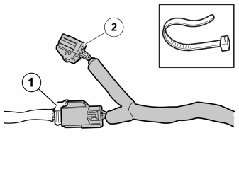
- Connect the cable harness to the pre-routed connector (1).
- Tape one cut piece of foam tape around the connectors.The pre-routed connector is already connected on certain versions. Disconnect it and then connect both the connectors from the new cable harness in-between. Secure the connector (2) on the car's existing cable harness using a cable tie.
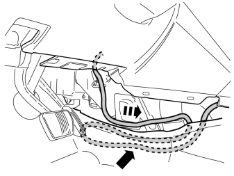
- Place any excess under the carpet.
Steps 31-36 apply when connecting to the USB/iPod player located in the glove compartment.
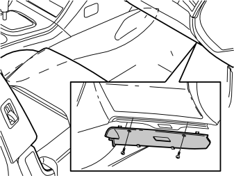
- Remove the sound barrier on the passenger side by first removing the two screws and then prizing it away at the top edge.
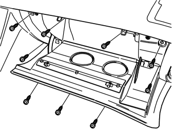
- Remove the nine screws, route the glove compartment straight out and disconnect the connector.
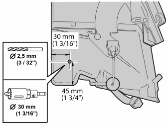
- Mark as illustrated on the outside of the glove compartment's end.
- Pre-drill using a Ø 2.5 mm (3/32") bit.
- Drill using a Ø30 mm (1 3/16") hole saw.
- Smooth off the hole edges.
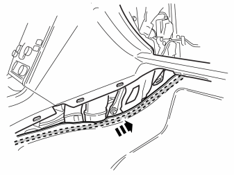
- Route the cable for the USB/iPod under the carpet along the side of the tunnel console.
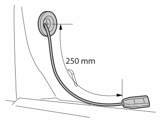
- Route the cable through the drilled hole.
- Thread the rubber grommet on to the cable and secure in the hole. The cable must protrude about 250 mm.
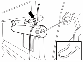
- Secure the cable using a cable tie on the damper spring's eyelets.
- Reinstall the glove compartment.
Steps 37-45 apply when connecting to the USB/iPod player located in the CD compartment under the armrest.
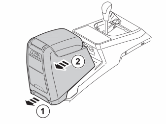
- Pull the handle, move the tunnel compartment backward and lift it away.
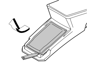
- Remove the cover. It shall not be re-used.
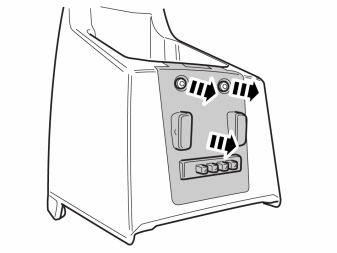
- Remove the two screws and the cover panel.
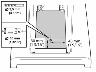
- Measure the front of the CD compartment as illustrated.
- Pre-drill using a Ø 2.5 mm (3/32") bit.
- Drill using a Ø30 mm (1 3/16") hole saw.
- Smooth off the hole edges.
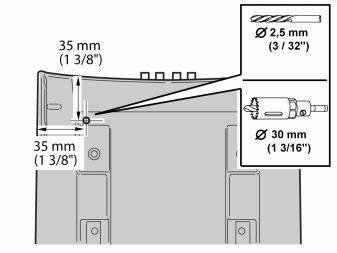
Applies to cars without holes in the tunnel compartment.
- Measure the bottom of the tunnel console as illustrated.
- Pre-drill using a Ø 2.5 mm (3/32") bit.
- Drill using a Ø30 mm (1 3/16") hole saw.
- Smooth off the hole edges.
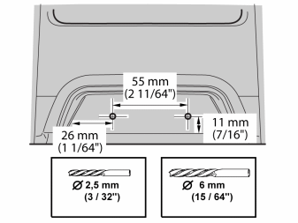
- Measure the opening handle of the tunnel console as illustrated.
- Pre-drill using a Ø 2.5 mm (3/32") bit.
- Drill out the holes. Use a Ø6 mm (15/64") diameter drill bit.
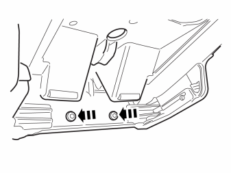
- Take the blind cover plug and two screws from the kit. Install the blind cover plug on the opening handle.
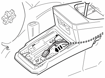
- Route the USB/iPod cable from the control module up out of the rear section of the tunnel console.
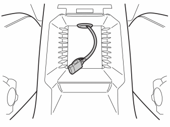
- Route the cable through the drilled holes.
- Insert the rubber grommet onto the cable and secure in the hole. The cable protrusion should be approx. 200 mm.
- Reinstall the contact plate.
- Reinstall the tunnel compartment and at the same time place the excess cable under the tunnel compartment.
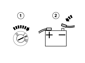
Applies to cars with Internal amplifier
- Turn the ignition key to position II.
- Reconnect the battery negative lead.

Reinstall:
- the panel to the gear selector
- sound proofing panels
- side panels
- Download the software for the accessory's function following the service information in VIDA.
Обсуждение и оценка
0Пока нет комментариев. Будьте первым.