Применимость
| Модель | Двигатель | Год |
|---|---|---|
| C30 | — | 2007–2011A |
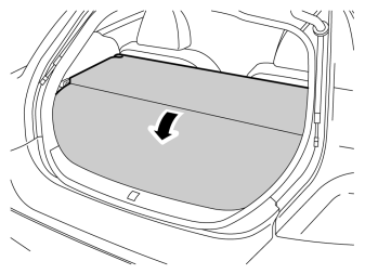
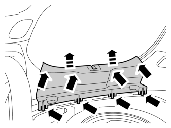
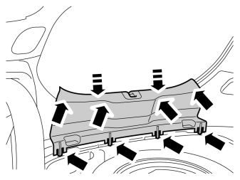
- Remove the tailgate's sill panel by pulling it up until the four clips on the upper side and the eight catches at the lower edge release.
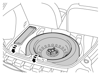
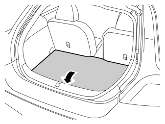
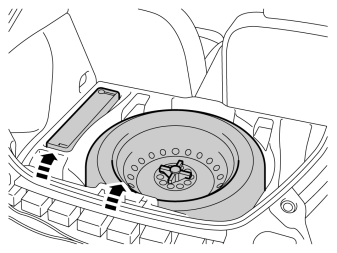
- Lift out the spare wheel, jack and other parts from the storage compartment in the cargo floor support.
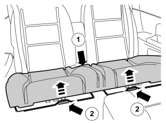
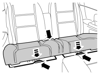
- Pull off the seat cushion, first at the rear edge where it is secured by one holder. Then at the front edge where it is secured by two holders.
- Remove the seat cushion.
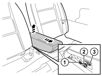
- Fold the central arm rest forward.
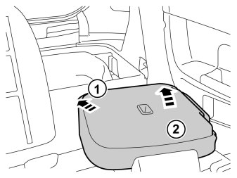
- Remove the central arm rest by grasping each end and pulling upwards until it releases at the rear edge from the backrest's lugs (1).
- Then pull forwards until the holders (2) on the sides of the backrest have slid out of the corresponding cut-out (3) in the central arm rest.
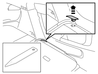
- Fold the backrest forward.
- Remove the panel for the backrest's left-hand mounting.
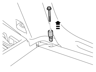
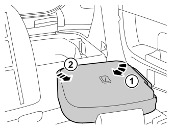
- Fold the backrest away from the left-hand mounting.
- Pull it out from the mounting at the arm rest and remove it.
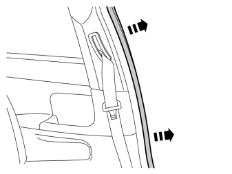
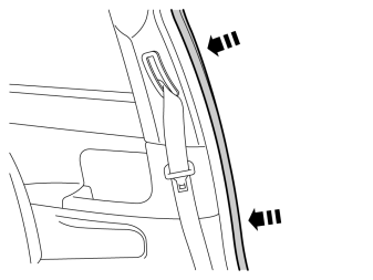
- Pull off the rubber molding at the rear edge of the left-hand door opening.
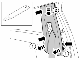
- Remove the B post panel by prying it off at the sides at the lower edge using a weatherstrip tool. It is secured by three clips on the inside.
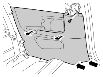
- Remove the screw from the left-hand panel in the rear seat.
- Carefully pull the panel from the body side and unhook it from the sill panel at the front edge. It is secured by eleven clips on the inside.
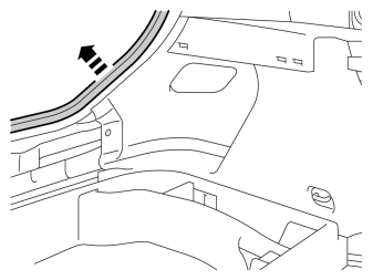
- Pull off the rubber molding on the left-hand side in the cargo compartment opening.
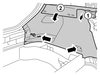
- Remove the clips at the rear edge of the left-hand rear side panel.
- Carefully pull the side panel off, starting at the front edge/upper edge and then straight back until all clips at the top edge have released.
- Fold the panel inwards. Release it from the anchorage eyelets and lift it out of the load floor support.
- Repeat steps 8-15 on the right-hand side.
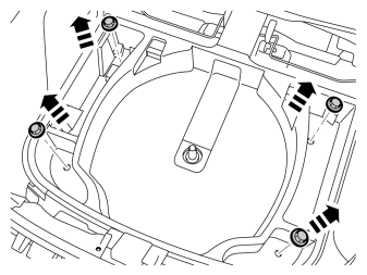
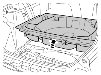
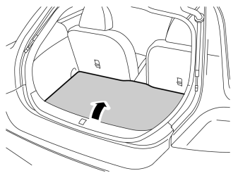
- Lift up the load floor support and slide it forwards in the cargo compartment.
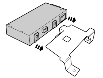
- Press the Trailer Module (TRM) into the bracket (Obtained separately).
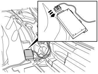
- Connect the two pin gray connector on the tow hitch cable harness to the trailer module (TRM).
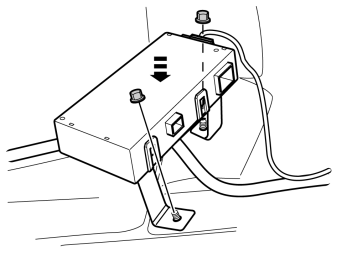
- Press the trailer module (TRM) into the lugs on the cargo compartment floor at the rear edge of the right-hand wheel arch.
- Press the two plastic nuts into place (Found in the kit for the tow hitch cable harness).
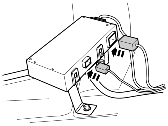
- Connect the gray 2 pin and green 5 pin pre-routed connector to the trailer module (TRM).
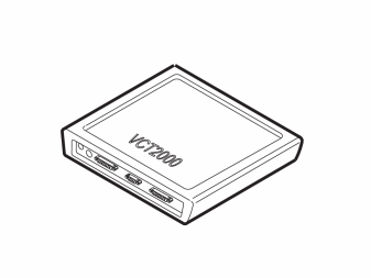
- Program the software for the selected version of cable harness according to the service information in VIDA.
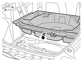
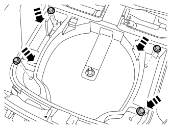
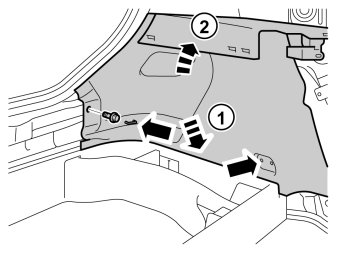
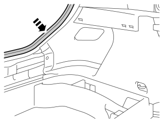
Illustration A
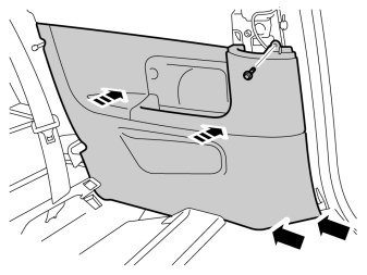
- Replace broken clips.
- Press the panel into place and ensure that all clips engage.
Примечание: There are eleven clips on the rear of the panel that secure to the body. Take care not to snap the clips when aligning.
- Tighten the panel using existing screws.
Illustration B
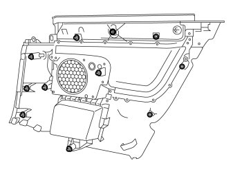
- The image shows the location of the clips on the rear of the panel.
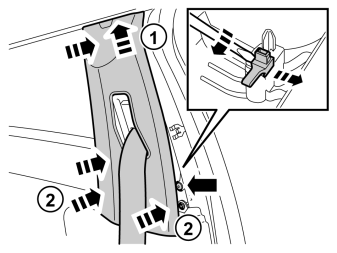
- Twist off the black plastic clip on the inside at the front edge using a screwdriver and replace with a new one. Reinstall the B post panel.
- Reinstall the backrest. Check that it is securely in its mountings.
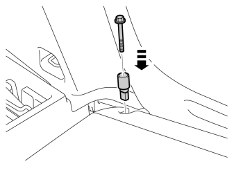
- Secure the backrest in the left-hand mounting with the screw and lock pin.
- Tighten the backrest and check that it is securely in its mountings. Tighten the screw to 25 Nm (18.5 lbf.ft.).
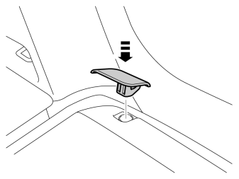
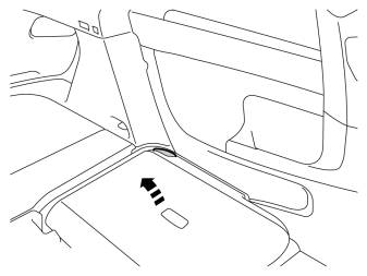
- Repeat steps 25 - 33 on the other side.
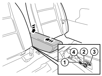
- Reinstall the central arm rest by grasping each end, moving it up towards the backrest lugs (1) and aligning the holders (2) in the backrest's sides in the central arm rest's cut-out (3).
- Then press the central arm rest down at the rear edge so that the lugs (1) engage in the cut-out (4). A click should be heard when the central arm rest is secured.
Обсуждение и оценка
0Пока нет комментариев. Будьте первым.