Применимость
| Модель | Двигатель | Год |
|---|---|---|
| XC60 | — | 2009–2010A |
Примечание: The installation instructions only apply to left-hand drive vehicles.
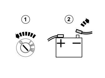
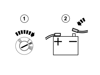
- Turn the ignition key to position 0.
- Disconnect the battery negative lead.
Примечание: Wait at least three minutes before unplugging the connectors or removing other electrical equipment.
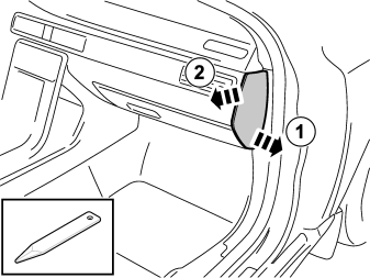
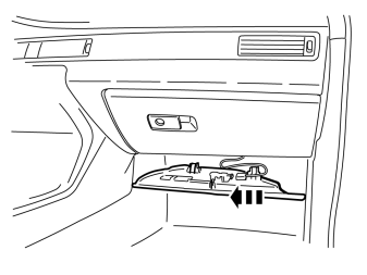
- Remove the panel.
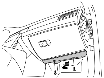
- Remove the screws.
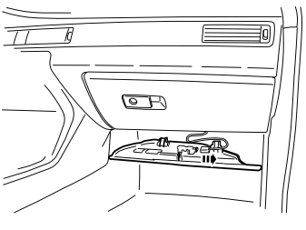
- Unplug the connector.
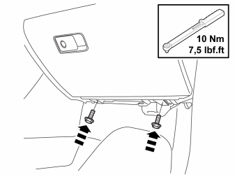
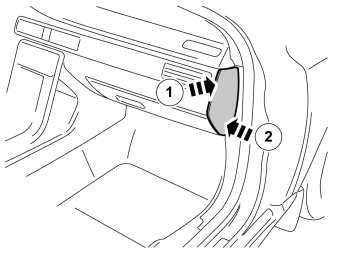
- Remove the panel.
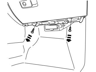
- Remove the screws.
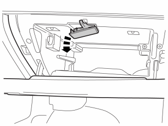
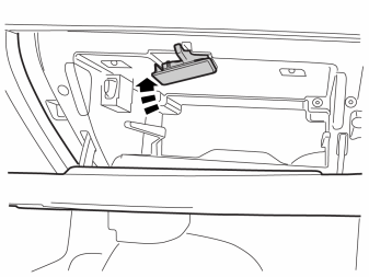
- Carefully pry off the lighting.
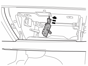
- Unplug the connector.
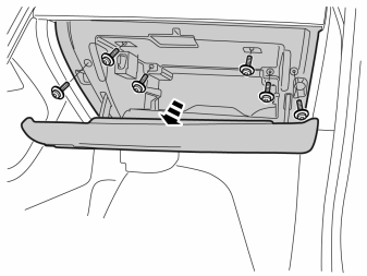
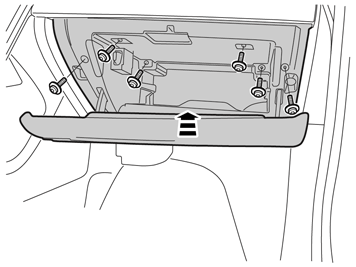
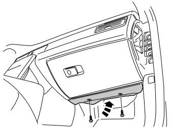
- Remove the six screws and remove the glovebox.
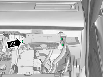
- Remove the three screws for the control module inside the glovebox and remove it.
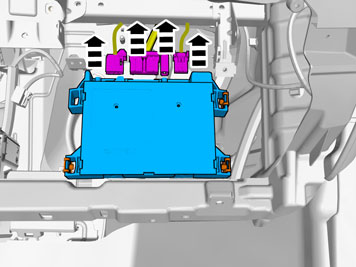
- Unplug the connectors.
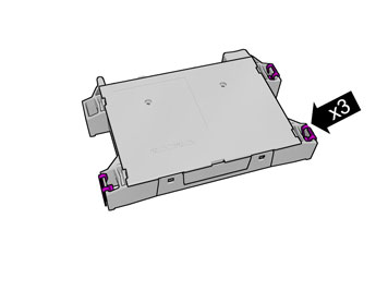
- Remove the spring nuts. They will not be used again.
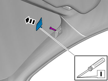
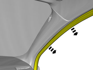
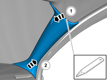
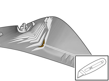
- Cut out the disc.
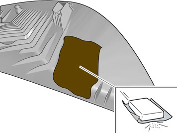
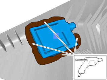
- Roughen the marked area on the A-pillar panel with sand paper.
- Remove the swarf residue.
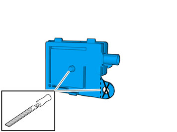
- Remove the GPS antenna from the kit and file off the marked parts.
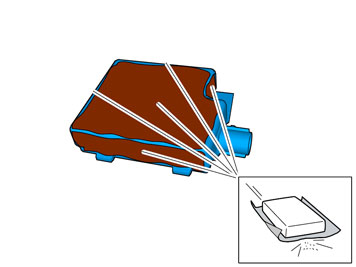
- Roughen the marked surfaces on the GPS antenna with sand paper.
- Remove the swarf residue.
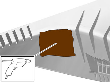
- Use adhesive pistol and adhesive stick part.no.1161853.
- Apply the adhesive thickly to the marked surface.
Illustrations A and B
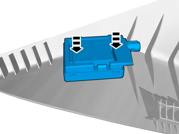
- Press the GPS antenna in the position displayed. The surface is not flat, but position it so that it there is equal clearance on each side of the underside. Fill around the edges of the antenna with adhesive.
Примечание: Ensure that no adhesive gets on to the switch or on the front side of the panel.
Applies to vehicles with a sunroof
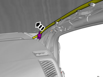
- Disconnect the drainage hose.
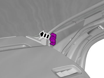
- Remove the holder. It will not be used again.
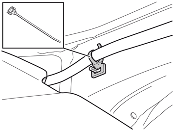
- Remove the cable tie from the kit and press into place where the holder was located.
- Tighten the drainage hose.
Applies to all models
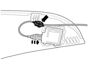
- Connect the cable from the kit to the antenna and secure it using a piece of butyl tape to fix it when installing.
Illustrations A and B
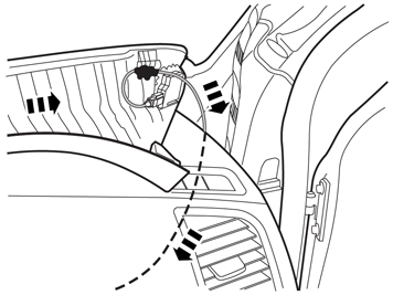
- Insert the cable through the hole in the dashboard end and route it forward.
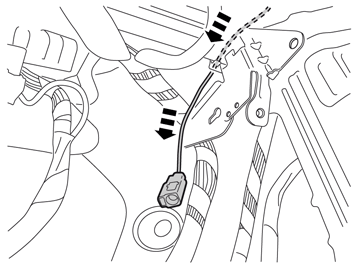
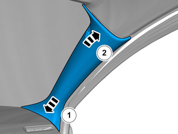
Примечание: Check that the cable is not trapped when the panel is put back.
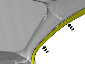
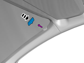
- Position the control module where the glove box was located.
- Connect the cable (1) from the GPS.
- Connect other cables that were disconnected from the control module.
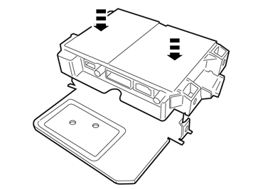
- Install the control module in the bracket from the kit.
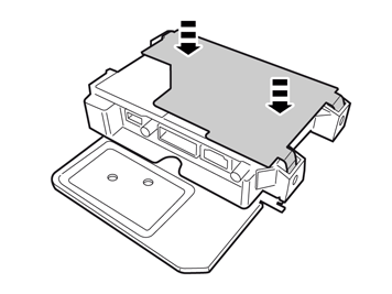
- Press the upper section into place.
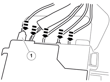
- Connect the connector (1) to the cable from the antenna.
- Connect the remaining connectors.
Illustrations A and B
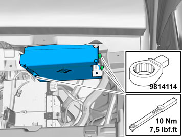
- Tighten the unit with existing screws. Use special tool 9814114.
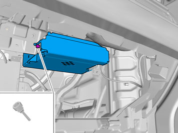
- Take the security screw form the kit and tighten until it breaks off.
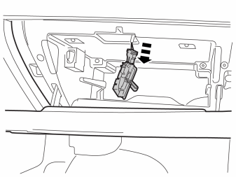
- Turn the ignition key to position II.
- Reconnect the battery negative lead

- Download the software (application) for the accessory's function following the service information in VIDA.
Обсуждение и оценка
0Пока нет комментариев. Будьте первым.