Применимость
| Модель | Двигатель | Год |
|---|---|---|
| S80 (07-) | — | 2007–2015A |
Color symbols
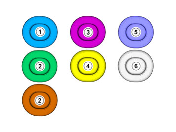
- Used for focused part, the part that you are to do something with.
- Used as extra colors when you need to show or highlight additional parts.
- Used for fasteners to be removed/installed. May be screws, clips, connectors, etc.
- Used when part is not removed completely from the vehicle but is only hung/suspended off to the side.
- Used for standard tools and special tools.
- Used as background color on vehicle parts.
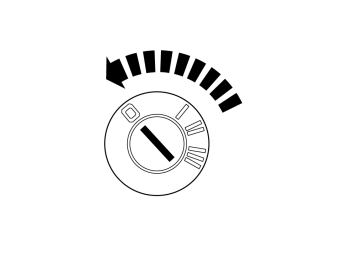
- Set the ignition key to position 0.
Примечание: Wait at least one minute before unplugging the connectors or removing other electrical equipment.
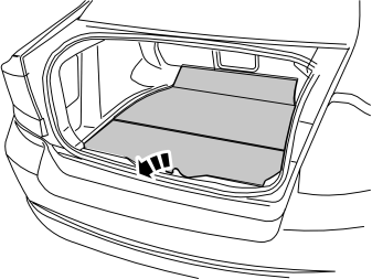
- Lift out the cargo compartment carpet.
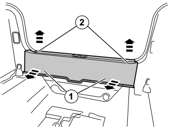
- Remove the sill panel by first pulling it forward until the two clips at the leading edge release.
- Then pull up until the two clips at the top edge release.
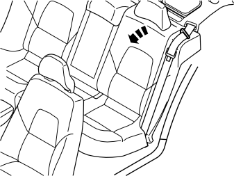
- Fold the left-hand rear seat backrest forward.
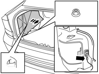
Remove:
- the three clips in the top edge of the side panel.
- the four plastic nuts in the lower edge of the side panel.
- the connector for the trunk lighting.
- Lift out the side panel.
Installing TRM
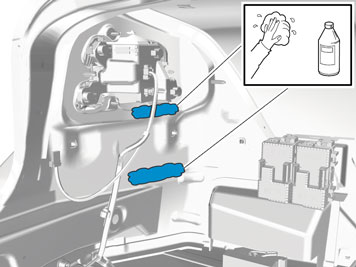
- Use:Isopropanol, 1161721 Wipe off.
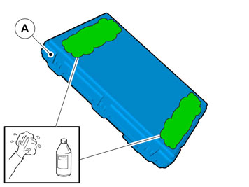
- Use:Isopropanol, 1161721 Wipe off.
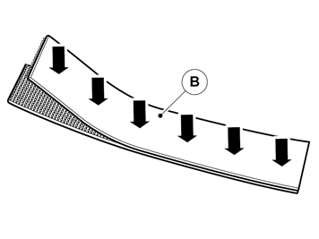
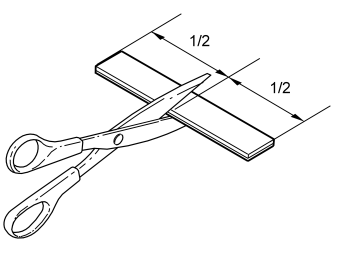
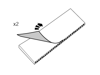
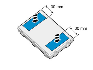
When installing Velcro tape the surface must maintain a temperature of at least +20 ° C (68°F).
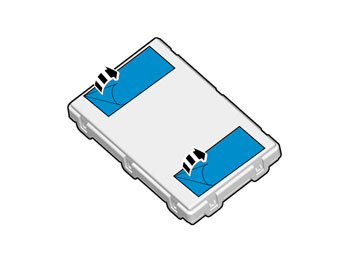
When installing Velcro tape the surface must maintain a temperature of at least +20 ° C (68°F).
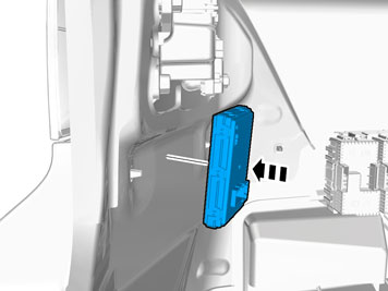
- Press the control module into place properly.
Applies to cars equipped with rear parking camera.
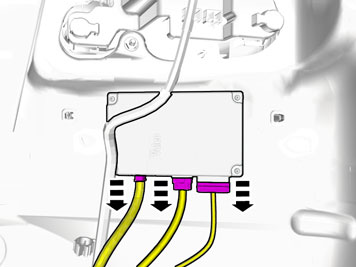
- Unplug the connectors.
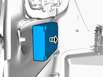
- Remove the control module. It is fastened with Velcro straps.
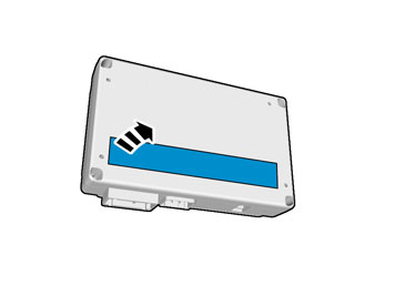
- Remove the Velcro strap on the back of the control module.
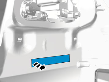
- Remove the Velcro strap
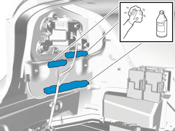
- Remove the remains of glue
Use:Isopropanol, 1161721 Wipe off.
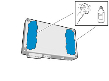
Use:Isopropanol, 1161721 Wipe off.
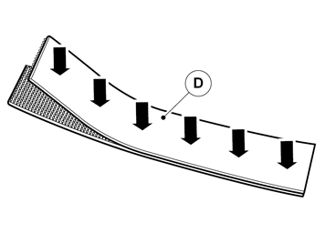
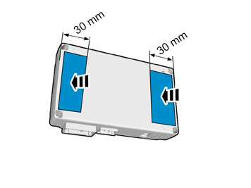
When installing Velcro tape the surface must maintain a temperature of at least +20 ° C (68°F).
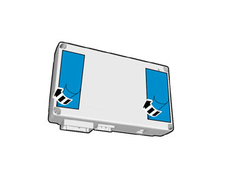
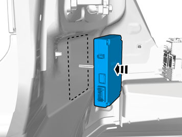
When installing Velcro tape the surface must maintain a temperature of at least +20 ° C (68°F).
- Press the control module into place properly.
- Use:Isopropanol, 1161721 Wipe off.
When installing Velcro tape the surface must maintain a temperature of at least +20 ° C (68°F).
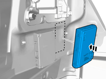
When installing Velcro tape the surface must maintain a temperature of at least +20 ° C (68°F).
- Press the control module into place properly.
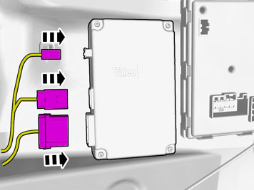
- Connect the connectors to the control module.
Applies to all models
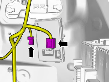
- Locate the connectors in the car's cable harness.
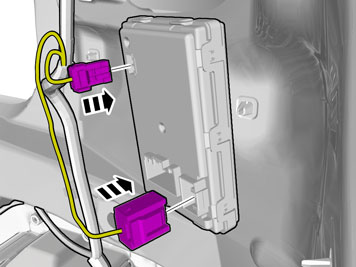
- Connect the connectors to the control module.
Installing trailer hitch cable harness
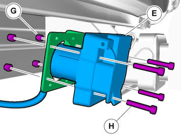
- Get four screws and nuts from the kit and install the socket (outlet) on the bracket.
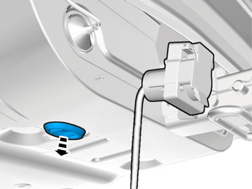
- Remove the rubber grommet in the floor and place it to one side, it shall not be used again.
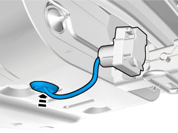
- Insert the cable with the connector into the hole in the spare wheel well and install the rubber grommet.
- Adapt the length of the cable from the connector to the rubber grommet so that the cable is not too slack beneath the car.
Примечание: Install the rubber grommet so that the cable points to the left on the inside.
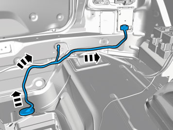
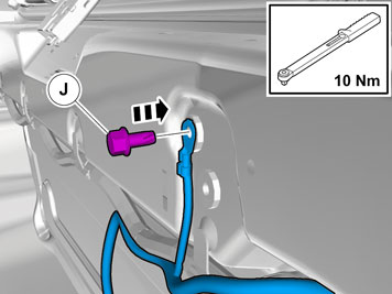
- Get the ground screw from the kit and tighten down the ground cable in the grounding point in the rear harness. Torque-tighten the bolt, tightening torque: 10 Nm
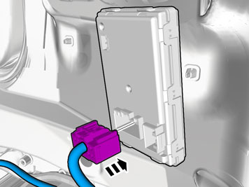
- Plug the green connector into the Trailer Module (TRM).
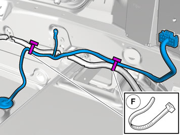
- Clamp up the cable harness at the existing cable harness using two tie straps from the kit.
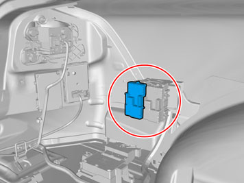
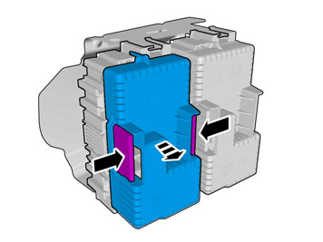
- Press in the catches on the black lid on the fuse holder and remove it.
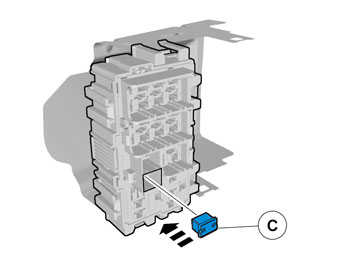
- Install 40A fuse in position FA11.
Applies to all models
- Reinstall the detached components in reverse order.

- Download software (application) for the accessory's function according to service information in VIDA. See VIDA or accessories catalogue for article number on software.
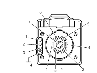
Checking the trailer connector7-pin connection
- Brake lamp / Left-hand indicator lamp
- Ground
- Spare (Brake lamp, Electric brakes)
- Brake lamp / Right-hand indicator lamp
- Charging
- Position lamps
- Spare (Reversing lamp)
The cable for pin 3 for 7-pin connection is blue (BL). It is taped on the cable harness approx. 1 meter from the trailer socket.4-pin connection
- Brake lamp / Right-hand indicator lamp
- Brake lamp / Left-hand indicator lamp
- Position lamps
- Ground