Применимость
| Модель | Двигатель | Год |
|---|---|---|
| V70 (00-08) | — | 2000–2008 |
Примечание: Kit contents:
- Crossmember
- Screw M14x80 (x2)
- Nut M14 (x2)
- Upper bracket (x2)
- Lower bracket (x2)
- Sleeve (x4)
- Screw M12x50 (x2)
- Screw M12x130 (x4)
- Reinforcement panel with sleeves (x2)
- Blind rivet (x12)
- Washer (x2)
- Rubber tab (x4)
- Connecting rod
- Sleeve (l=12.5 mm) (x4)
- Screw M12x100 (x2)
- Nut M12 (x2)
- Bracket, trailer connector
- Bracket, safety cable
- Towball
- Screw M16x50 (x2)
- Nut M16 (x2)
- Screw 4.8x9.5
Type approval of the towbar is in the table on page 2.
Примечание: A new lining mat is required for cars manufactured up to week 13, 2000. The lining mats are ordered separately for these cars (P/N 8625515).
Примечание: It is recommended that the work at steps 6 and 17 is carried out by two people.
- Turn the ignition key to position 0. Remove the ignition key from the ignition switch.
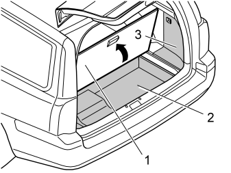
- Fold up and remove the floor hatch (1).
- Fold up and remove the storage cover (2).
- Remove the side panel (3) on the right-hand side.
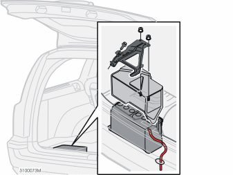
Remove:
- the holder for the battery cover, by removing the two nuts in the front edge of the holder and the screw in its rear edge.
- the battery cover.
- the battery negative lead.
- the battery, or move the battery to facilitate access.
Illustration A
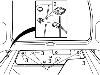
Applies to cars with lining mats with four perforations
- Remove the perforated sections (3) from the lining mat.
Applies to cars with lining mats with one perforation
- Remove the lining mat.
Applies to all cars
- Remove the nuts (1) for the bumper.
- Separate the connector (2) for the antenna.
Illustration B
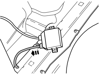
Applies to cars with parking assistance
- Detach the parking assistance module (PAM) from its location on the member on the left-hand side of the cargo compartment.
- Detach the smaller connector from the control module.
Illustration A applies to cars with mudflaps
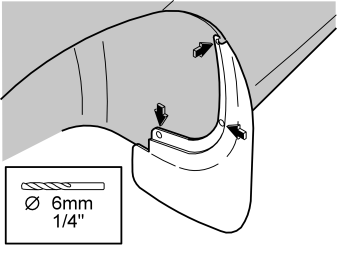
- Carefully drill out the rivets for the mudflap. Use a Ø6 mm (13/32") diameter drill bit.
- Remove the mudflaps.
Illustration B applies to all cars
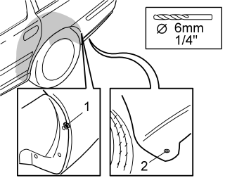
- Carefully drill out the rivet (2) underneath the bumper. Use a Ø6 mm (13/32") diameter drill bit.
- Remove the screw (1).
Примечание: Do not damage any of the plastic components.
Applies to all cars
- Raise the car.
- Remove the rear wheels.
Illustration A
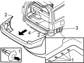
- Remove the clips (1) underneath the bumper cover by pressing in the centre of the clips until a click is heard. The clips shall be re-used.
- Pull the bumper backwards slightly. Bend out the sides (2) so that they detach from the mounting (3). Continue to pull backwards until the bumper detaches completely.
- Place the bumper on a clean underlying surface that will not damage the paint.
Applies to cars with mouldings
- Carefully remove the moulding (4) from the expander clips.
Illustration B

Applies to cars with parking assistance
- Detach the bumper in accordance with the above. Carefully pull the cable (1) out through the hole in the car.
- Place the bumper on a clean underlying surface that will not damage the paint.
Illustration A applies to the left-hand side
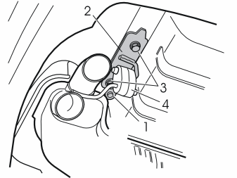
Remove:
- the rivet (1) on the bracket (2) for the silencer. Use cutting nippers.
- the screws (3) on the bracket.
- the bracket by detaching the rubber mounting (4). The bracket shall not be re-used.
Illustration B applies to the right-hand side
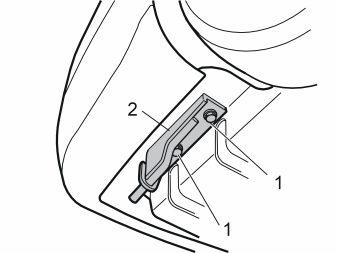
- Remove the screws (1). Remove the bracket (2). The bracket shall not be re-used.
Illustration A
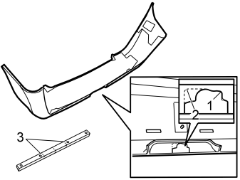
- Install masking tape on the outside of the bumper cover to avoid damage from the base of the saw.
- Mark on the inside of the bumper in accordance with the dotted line (2) on the illustration (for the bracket to the safety cable)
- Cut along the markings (1, 2) in accordance with the illustration.
- After cutting, smooth off the edges using a file.
Applies to cars with mouldings
- In addition, cut out the moulding in accordance with the markings (3).
Illustration B applies to the V70R (CH —458999)
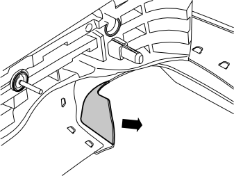
Cutting points, exhaust pipe clip
- Apply masking tape on the outside of the exhaust pipe clip to avoid damage from the saw. Leave the masking tape in place during installation.
- Cut along the marked raised area and remove the cut-out area.
- After cutting, smooth off the edges using a file.
- Clean away any underseal and dirt from the surfaces between the towbar kit and the bodywork.
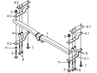
The illustration shows the assembly of the towbar kit.
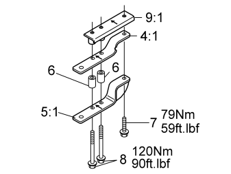
Carry out on both sides, (the right-hand side is illustrated)
- Install the screws (7, 8) from underneath the brackets (4:1, 5:1, 9:1), including the sleeves (6). Tighten by hand. The arrows on the brackets (4:1, 5:1, 9:1) must point in towards the centre of the car.
Illustration A
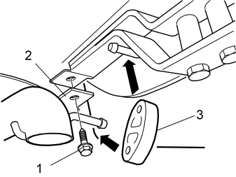
Illustration B
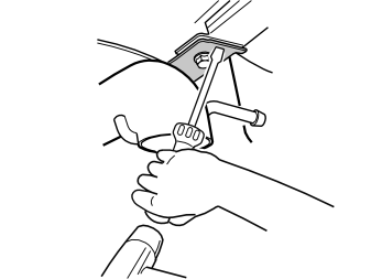
Carry out in accordance with illustration A and B
- Install the heat deflector plate (2) using the screw (1) loosely.
- Bend the heat deflector plate using a screwdriver, as illustrated.
- Tighten the screw.
- Reinstall the rubber mounting (3) for the silencer. Use normal soap to facilitate installation.
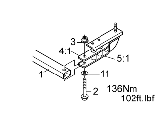
Carry out on both sides, (the right-hand side is illustrated)
- Insert the member (1) between the brackets (4:1, 5:1) and centre around the holes.
- Install the screws (2) and washers (11) from underneath the bracket (5), and the nuts (3) from above, without tightening.
- Check that the distance between the member (1) and the spare wheel well is 10 mm (25/64") and centre the towbar against the car.
Carry out on both sides
- Tighten the screws (7). Tighten to 79 Nm (58 lbf.ft.)
- Tighten the screws (8). Tighten to 120 Nm (88 lbf.ft.)
Carry out on both sides
- Tighten the screws (2) and the nut (3) to 136 Nm (100 lbf.ft.).
Carry out on both sides
- Wait at least five minutes, so that the joint has time to set. Then tighten the screws (8) on both sides, a quarter turn (angle tighten 90°).
Примечание: Torque tightened screws and nuts that have been removed must not be re-used.
Applies to all markets
- Underseal the car (in Sweden only after the state roadworthiness inspection).
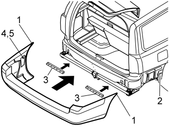
Applies to cars with mouldings
- Reinstall the mouldings (3) on the expander clips. Press the mouldings into place.
Applies to all cars
- If the guide lugs (4) and clips (5) have loosened, reinstall them.
- Applies to cars with parking assistance: Lift up the bumper in position. Pull the cable for the sensors through the hole for the bumper's guide, and pull the cable in from the inside.
- Reinstall the bumper by pressing it forwards. Ensure that the four screws protruding from the bumper align with the holes in the car. Before the bumper is completely installed, slide the top edge (1) into the grooves. Then slide the bumper fully in.
- Check that the guide lug (4) and clip (5) are centred with the hole in the wheel arch lining.
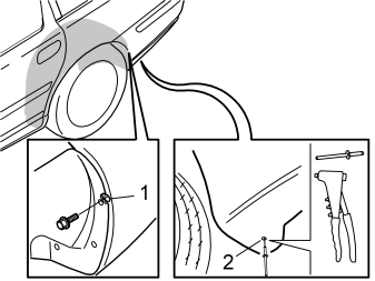
- Tighten the screw (1) on both sides.
- Rivet (2) in the bumper in the lower edge of the wheel arch.
Applies to cars with clips and mouldings
- Reinstall the clips underneath the bumper. Ensure that the clip locks are in the normal position.
Applies to all cars
- Reinstall the nuts. Tighten the nuts. Tighten to 18 Nm (13 lbf.ft.).
- Plug in the antenna's connector.
Applies to cars with mudflaps
- Rivet in the mudflaps.
Applies to all cars
- Reinstall the wheels and tighten the screws crosswise. Tighten to 110 Nm (81 lbf.ft.).
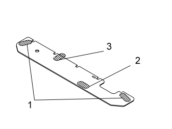
Applies to cars with lining mats with four perforations
- Install the rubber tabs from the kit over the four exposed screws as follows:Align the rubber tabs (1) edge to edge with the lining mat.Compress the rubber tab (2) slightly to align in the cut-outAlign the rubber tab (3) so that the lower edge is edge to edge with the lining mat. Cut off the section protruding over the lining mat. Do not cut off too much.
Applies to cars with lining mats with one perforation
- Install a new lining mat.
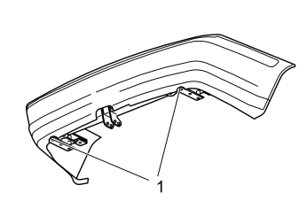
- If necessary, cut away the area (1) around the screw heads, so that the screws are accessible.
- Install the connecting rod (13) with sleeves (14), screws (15) and nuts (16) together with trailer connector with bracket (17) and the safety cable bracket (18) from the kit, see kit illustration on page 2.Fit them horizontally. The screws are inserted from the left-hand side with the trailer connector with bracket and the safety cable's bracket located in the rear hole.
- Tighten the screws. Tighten to 90 Nm (68 lbf.ft.).
Внимание: Post-tighten the screws after approximately 1000 km.
- Install the cable harness connector for the towbar according to step 1 in the appropriate Installation Instructions.
- Install the cable harness for the towbar according to step 2 onwards in the appropriate Installation Instructions.
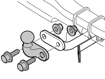
- Install the towball on the connecting rod with the intended screws and nuts from the kit. The nuts must be on the inside.
- Tighten the towball, tighten to 195 Nm (144 lbf.ft.).
Внимание: The nuts for the towball may only be used once.
- Applies to cars with parking assistance: Connect the detached cable to the parking assistance module (PAM). Reinstall the control module.
- Turn the ignition key to position II.
Reinstall:
- the battery negative lead
- the battery cover and holder
- the side panel in the cargo compartment
- the storage cover and the floor hatch
- the floor carpet
- Remove the protective tape from the bumper.
Обсуждение и оценка
0Пока нет комментариев. Будьте первым.