Применимость
| Модель | Двигатель | Год |
|---|---|---|
| XC90 | — | 2003–2005 |
Примечание: Kit contents:
- Cross member
- Screw M12x110 (x6)
- Spacer washer, left-hand
- Spacer washer, right-hand
- Protective cover, assembly
- Strap
- Bracket
- Nut M6
- Protective bag
- Decal
- Detachable tow hitch
- Cover plate (x4)
- Mounting pin (x2).
Type approval of the tow hitch is in the table on page 2.
Illustration A
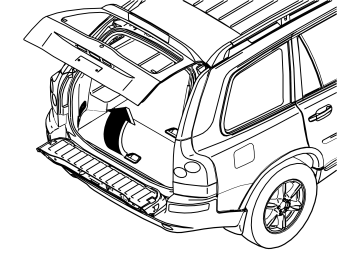
Applies to cars with two rows of seats
- Fold up the centre rear floor hatch (1) slightly
- Remove the hatch by pulling it off the mountings at the front edge
- Remove the storage box underneath and lift it out. If the floor hatch has a carrier bag holder on the underneath, it is secured by a strap on each of the shorter sides of the storage box. These straps must be undone.
Illustration B
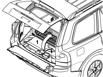
Applies to cars with three rows of seats and the integrated carrier bag holder on the underside of the centre floor hatch
- Fold up the centre rear floor hatch (1)
- Release the two straps on the panel underneath. Lift up the panel at the rear edge. Fold back the floor hatch towards the panel. Lift out the floor hatch and panel.
Applies to cars with three rows of seats without an integrated carrier bag holder
- Fold up the centre rear floor hatch (1) at the rear edge and lift it out.
Illustration C
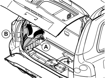
Applies to all models
- Remove the side floor hatches (A) and the folding side panels (B) on the right and left-hand sides in the cargo compartment.
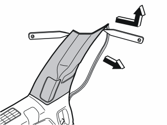
- Pull off the rubber strip at the rear edge of the door opening for the left-hand rear door opposite the left C-post panel
- Carefully pry off the left-hand C-post panel at the sides at the top edge. Use a plastic weatherstrip tool. Pull off until the three clips on the inside release. Do not damage the headlining or the panel
- Remove the panel by pulling upwards slightly and unhooking it from the side panel
- Repeat the operation on the right-hand side.
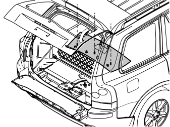
- Remove the covers and the screws underneath for the rear headlining
- Carefully pry off the panel at the rear edge. Use a plastic weatherstrip tool
- Pull the rear edge of the panel downwards until all clips on the inside have released
- If the car has lighting in the panel, disconnect the connector
- Pull the panel backwards to release it.
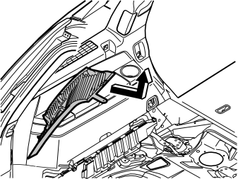
- Carefully pull off the left-hand D-post panel starting at the top edge. Then pull downwards until the three clips on the inside have released. Do not damage the panel
- Remove the panel by pulling upwards slightly and unhooking it from the side panel
- Disconnect the connector if the car has a loudspeaker in the D-post
- Repeat the operation on the right-hand side.
Illustration A shows the removal of the cover for the load securing eyelets
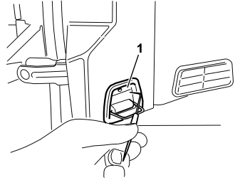
Applies to all models
- Fold out the load securing eyelet
- Insert a scriber with an angled tip into the hole in the top of the cover
- Turn the scriber so that the angled tip engages in the reverse of the cover (1). Pull the cover off
- Repeat the operation on the right-hand side.
Illustration B applies to cars with two rows of seats
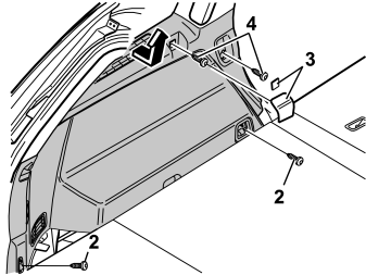
Illustration C applies to cars with three rows of seats
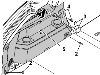
- Fold up the seats in the third row (applies to cars with three rows of seats)
- Remove the screws (2) for the load securing eyelets in the left-hand side panel
- Remove the covers (3) over the front mountings for the left-hand side panel. Pry the covers off. Use a plastic weatherstrip tool or a small screwdriver
- Remove the screws (4)
- Remove the clip (5) at the bottom of the storage compartment in the panel (Applies to cars with three rows of seats)
- Pull up the panel slightly at the top edge so that the clips on the inside release. Remove the panel by pulling it straight upwards.
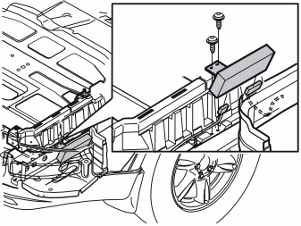
Applies to cars with accessory electronic modules (AEM)
- Remove the bracket and the accessory electronic module (AEM). If necessary disconnect the connectors.
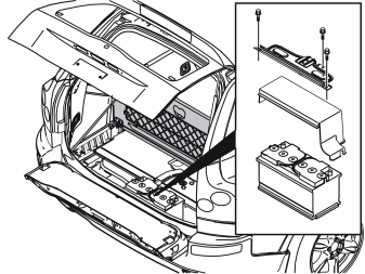
- Remove the three screws in the battery holder. Lift the battery holder out
- Remove the battery cover
- Lower and remove the spare wheel.
Illustration A
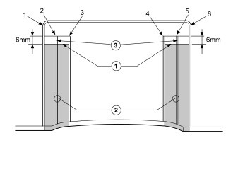
From underneath the car
- Measure and draw a horizontal line 6 mm below the top of the ribs as illustrated
- Cut along the inside of ribs 1 and 3 (the sides which face rib 2) up to the line drawn 6 mm below the top edge of the ribs. Do the same between ribs 6 and 4. Remove the shaded areas by cutting/sawing between the cuts along the horizontal line so that two parallel slits are made in the bumper cover
- Cut away the remaining pieces of ribs 2 and 5 parallel to the bumper cover.
- Use a file to smooth off the edges of the cut outs.
Illustration B
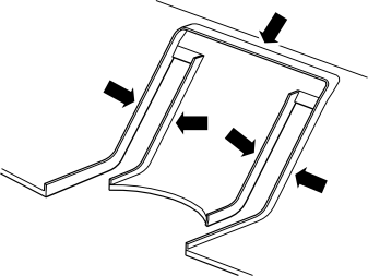
- Cut away all the upright ribs.
Illustration C
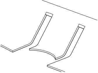
- The end result must be as illustrated.
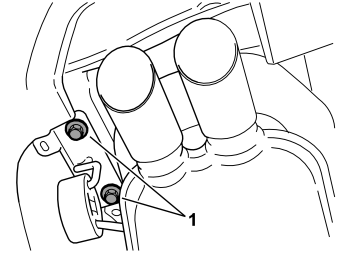
- Remove the rear mounting for the silencer and the bracket from the underneath of the left-hand rear side member by removing the screws (1). Remove the silencer to gain access when installing the tow hitch.
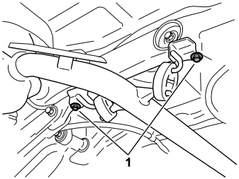
- Remove the front mounting for the rear silencer at the rear sub-frame by removing the screws (1)
- Carefully bend the heat deflector plate at the side member to one side, to gain more work space
- Remove the protective flaps covering the mounting holes on the inside of the side members (one on each side)
- Remove any sealant from the surface where the tow hitch member will be mounted.
Applies to cars equipped with a reversing warning system
Illustration A shows the right-hand side of the bumper
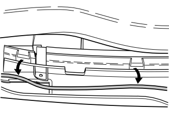
Illustration B shows the left-hand side of the bumper
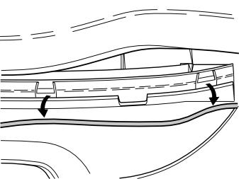
- Disconnect the cable for the reverse warning sensor from its clips in the rear section of the bumper.
Applies to all models
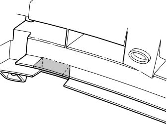
Right-hand side:
- Cut out the rear section at the existing cut out as marked in the illustration.
Applies to cars with reversing warning systems
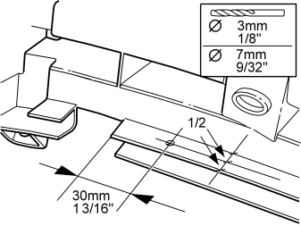
Right-hand side:
- Measure up to drill the cable lead-in in the upper of the rear section plates as illustrated
- Pre-drill using a 3 mm (1/8”) diameter drill bit. Then drill out the hole to a diameter of 8 mm (5/16”). Use an angle drill and short drill bits.
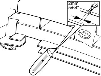
- Cut a 2 mm (5/64”) wide groove through the plate leading in to the hole.
Applies to all models
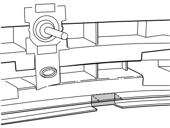
Left-hand side:
- Cut out the rear section at the existing cut out as marked in the illustration.
Applies to cars with reversing warning systems
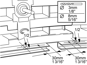
Left-hand side:
- Measure up to drill the cable lead-in on the left and right-hand sides of the cut-out in the upper of the rear section plates as illustrated
- Pre-drill using a 3 mm (1/8”) diameter drill bit. Then drill out the holes to a diameter of 8 mm (5/16”). Use an angle drill and short drill bits.
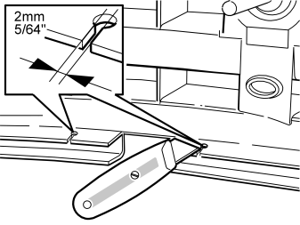
- Cut a 2 mm (5/64”) wide groove through the plate leading in to the holes on both sides of the cut-out.
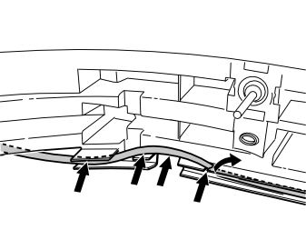
Right-hand side:
- Press up the tab on the plate. Insert the cable in the previously drilled hole. The cable must be positioned as illustrated.
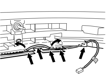
Left-hand side:
- Press up the tabs on the plates and insert the cable in the holes drilled earlier. The cable must be positioned as illustrated.
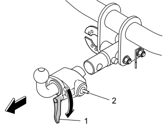
- Remove the tow hitch by turning the handle (1) to the right until a click is heard and the pin (2) is in the outer position. Pull out the hitch.
Примечание: The shaft is greased.
Illustration A
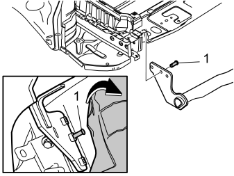
- Take the two mounting pins (1) from the kit
- With one person at each end, lift and position the tow hitch on the inside between the two side members, in between the holes. Start by angling up the face of the left-hand side above the tail pipe on the silencer and up between the heat deflector plate and the side member. Then angle the right-hand side face up to the side member
- Press the mounting pins into the centre hole in the side members while holding the tow bar member in position so that the bar can hang freely without falling off
- Carefully lower the car.
Illustration B
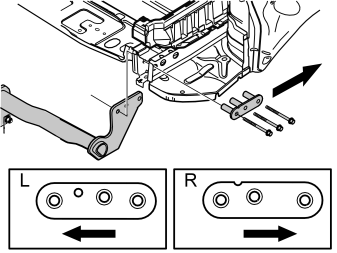
- Fold down the lower tailgate.
From the inside of the cargo compartment:
- Remove the protective flaps covering the mounting holes on the outside of the side members (one on each side)
- Remove any sealant from the surfaces where the spacer washers will be positioned
- Insert the spacer sleeves using only the front and rear screws on the outside of the two side members.
Примечание: Be careful when installing the spacer sleeves and screws so that they do not press out the mounting pins, causing the tow bar to detach.
- Screw the front and rear screws in fully but do not tighten them
- Insert the centre screws so that the mounting pins are pressed out. Screw the screws in fully but do no tighten them
- Hold the bar in the horizontal position. Tighten the screws.
Примечание: Rustproofing agent must be applied under the car before the screws are tightened. Apply the rustproofing agent to the side members all around the ends where any sealant was scraped off.
- Tighten all screws from inside the car. Tighten to 120 Nm (86 lbf.ft.) in the following order:1. The rear screws2. The front screws3. The centre screws
Примечание: Wait five minutes so that the joint settles. Then re-check the torque.
- Raise the car again.
Подсказка: It is recommended that two people carry out this procedure.
From underneath the car
- Carefully bend the heat deflector plate back into position so that it is not against the silencer
- Reinstall the front mounting for the rear silencer. Tighten the screws. Tighten to 24 Nm (18 lbf.ft.)
- Reinstall the rear mounting for the rear silencer. Tighten the screws. Tighten to 48 Nm (35 lbf.ft.).
- Install the cable harness connector for the tow hitch according to point 1D in the installation instructions for the appropriate cable harness.
- Install the cable harness according to point 3 onwards in the installation instructions for the appropriate cable harness.
Примечание: Ensure that the cable harness does not rub against the lower edge of the bumper and is not pressed back.
Illustration A displays installation of the tow hitch
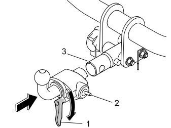
- Turn the handle (1) clockwise until a click is heard and the indicator pin (2) is in the outer position
- Install the tow hitch by pressing the tow hitch onto the connection stud (3).
Illustration B displays how to lock the tow hitch
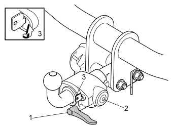
- Check that the indicator pin (2) is in the inner position and that the handle (1) is horizontal
- Turn the lock cylinder (3) to the position illustrated.
- Check the function of the detachable tow hitch.
Storing the tow hitch
Applies to cars with three rows of seats
Illustration A
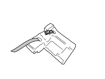
- Remove the storage box and the strap from the kit. Thread the strap through the holes in the storage box. See the illustration.
Illustration B
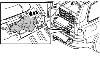
- Insert the storage box in the space to the right of the battery. Press the box into place against the floor. Be careful with the storage box. It is made of Frigolite which is brittle.
Illustration C
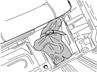
- Thread the supplied protective bag over the towing ball before removing the tow hitch
- Remove the tow hitch. Pull the string tight on the protective bag
- Position the removed tow hitch and bag in the storage box. The ball must be pointing forwards to the right. Tighten in position using the strap.
Applies to cars with two rows of seats
Illustration A
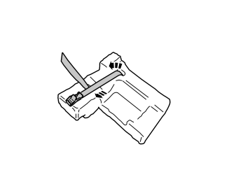
- Remove the storage box and the strap from the kit. Thread the strap through the holes in the storage box. See the illustration.
Illustration B
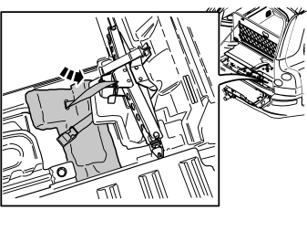
- Insert the storage box in the space to the right of the battery. Press the box into place against the floor. Be careful with the storage box. It is made of Frigolite which is brittle.
Illustration C
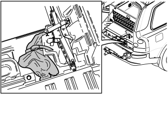
- Thread the supplied protective bag over the towing ball before removing the tow hitch
- Remove the tow hitch. Pull the string tight on the protective bag
- Position the removed tow hitch and bag in the storage box. The ball must be pointing forwards to the right. Tighten in position using the strap.
Finishing work
Illustration A
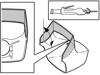
Applies to cars with a rear skid plate
- Saw or cut along the top of the markings on the inside of the cover as illustrated. Cut the material at right-angles. After cutting, smooth off the edges using a file.
Illustration B
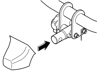
Applies to all models
- Install the cover on the connection stud. Press so that the cover is secure.
Осторожно: Do not use the cover as a step. There is a risk of personal injury by standing on the cover.
- Reinstall the protective cover and holder for the battery
- Reinstall the spare wheel.
Applies to cars with accessory electronic modules (AEM)
- Reinstall the bracket with the accessory electronic module (AEM). Connect the connectors if disconnected.
Applies to all models
- Reinstall the panels, storage boxes and floor hatches
- Tighten the screws in the load securing eyelets. Tighten to 24 Nm (18 lbf.ft.).
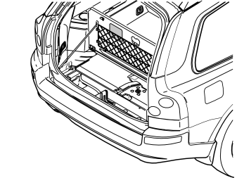
- Apply the decal supplied to the underside of the rear floor hatch as illustrated.
Обсуждение и оценка
0Пока нет комментариев. Будьте первым.