Применимость
| Модель | Двигатель | Год |
|---|---|---|
| S40 (04-) | — | 2004 |
| V50 | — | 2004 |
Примечание: This accessory is connected to the electrical system of the car. It requires software unique to the car.
Applies to 5 cylinder petrol engines (points 1-23 )
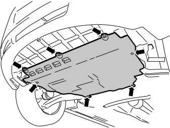
- Turn the seven clips 90°.
- Release the engine splash guard from the clips. Place the engine splash guard to one side.
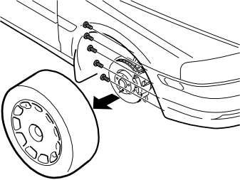
- Remove the right-hand front wheel
- Remove the five screws holding the bumper cover to the right-hand wing liner.
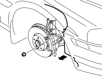
- Remove the nut holding the wing liner to the right-hand front member
- Bend the front edge of the wing liner up over the brake calliper.
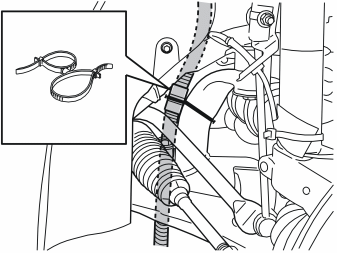
Applies to cars with only an electrical engine block
- Cut away the tie strap over the locking sleeve
- Release the cables from the front engine block heater socket from their clamps. This will make it easier to install the timer relay. If necessary, also disconnect the cable from the engine block heater
- Remove the locking sleeve over the cable junction. Pull the cables apart.
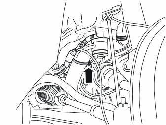
Applies to cars with an engine block heater and passenger compartment connector socket
- Release the cables from the front engine block heater socket and the engine block heater from their clamps. This will make it easier to install the timer relay
- Release the clamp securing the junction connector at the stay
- Remove the junction connector and cables from the clamp and the stay.
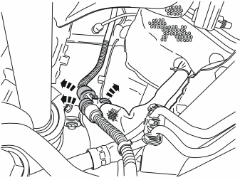
Applies to cars with an engine block heater and passenger compartment connector socket
- Remove the locking sleeves over the cable slices on the cables for the front engine block heater socket, the engine block heater and the passenger compartment connector socket
- Remove the cables from the junction connector
- Put the hose clamp and the holder together with the junction connector to one side. There are new components in the kit.
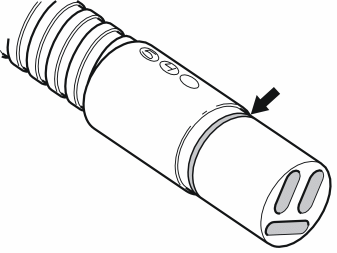
- Grease the O-rings on the cable for the front engine block heater socket, the timer relay and the cable to the passenger compartment connector socket (if the car has this). Use the low temperature grease (P/N 1161417-9).
Примечание: Do not get any grease on the contact surfaces of the connector.
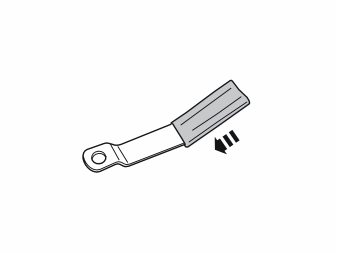
- Take the bracket and the rubber guard from the kit (or use the existing bracket and rubber guard). Press the rubber guard on to the bracket.
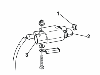
Applies to cars with only an electrical engine block
- Take the screw, the toothed washer and the nut from the kit. Tighten the timer relay at the holder in the position illustrated. The holder must be parallel to the length of the timer relay
- Press the cover (1) (P/N 346509, not included) into place on the free socket in the timer relay
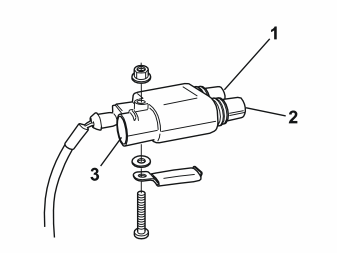
Applies to cars with a passenger compartment connector socket
- Take the screw, the toothed washer and the nut from the kit. Tighten the timer relay at the holder in the position illustrated. The holder must be parallel to the length of the timer relay
Illustration A
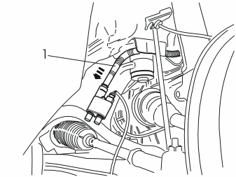
- Connect the cable (1) from the front engine block heater socket to the timer relay. Firmly press the cable junction together.
Illustration B
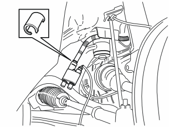
- Press the existing locking sleeve over the cable splice.
Applies to cars with only an electrical engine block Illustration A
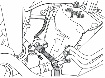
- Connect the cable (1) from the engine block heater to the timer relay. Firmly press the cable splice together.
Illustration B
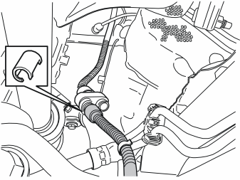
- Press a locking sleeve (from the kit) over the cable splice.
Applies to cars with an engine block heater and passenger compartment connector socketIllustration A
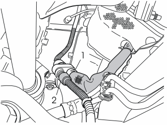
- Connect the cable (1) from the passenger compartment connector socket and the cable (2) from the engine block heater to the timer relay
- Firmly press the cable splices together.
Illustration B
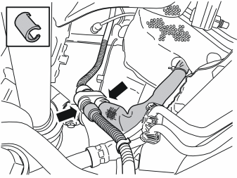
- Press the two locking sleeves (from the kit) over the cable splices.
Illustration A
- Install the holder and the connected timer relay on the stay using the hose clamp.
Illustration B
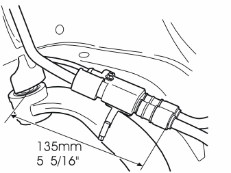
- Check that the measurements are the same as in the illustration.
- If the cables to the front engine block heater socket and the engine block heater were disconnected, reinstall them in their clamps.
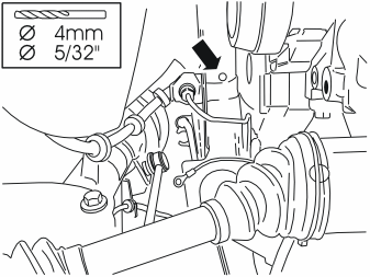
- Route the ground lead from the timer relay
- Drill a 4 mm (5/32”) diameter hole on the underside of the right-hand front member for the ground lead for the timer relay. Drill the hole centrally in the underside of the beam, opposite the brake pipe connection
- Remove any swarf. Rust-proof the edges of the holes.
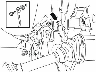
- Secure the ground lead in the front member using a screw and toothed washer from the kit
- Clamp the excess cable using a tie strap from the kit.
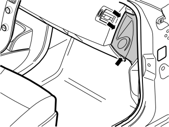
- Open the cover for the glove compartment
- Remove the panel on the right-hand end of the dashboard. Using a weatherstrip tool, carefully pry around the panel until the three clips on the inside release.
Примечание: Do not damage the dashboard.
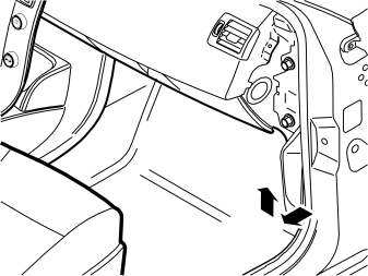
- Remove the sill trim panel from the right-hand front door. First pull off the front edge of the sill trim panel so that the clip there releases. Then continue backwards until the remaining clips on the underneath have released
- Unhook the sill trim panel from the B-post panel.
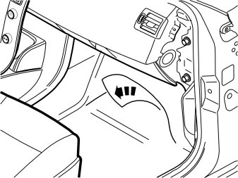
Applies to cars without a passenger compartment connector socket
- Fold the floor carpet to one side to access the lead-in in the cowl panel.
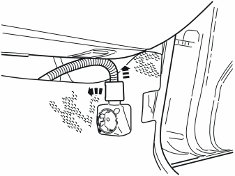
Applies to cars with a passenger compartment connector socket
- Remove the locking sleeve over the cable splice in the passenger compartment connector socket
- Disconnect the cable from the passenger compartment connector socket
- Remove the passenger compartment connector socket from its bracket
- Fold the floor carpet to one side to access the lead-in in the cowl panel.
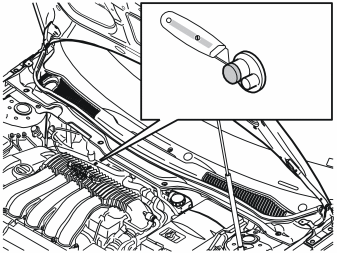
- Cut away the top of the small “rubber nipple” in the rubber grommet in the cowl panel. This is on the right-hand side of the engine compartment. Use a knife.
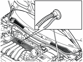
- Route the cable for the accessory electronic module (AEM) from the timer relay to the rubber grommet in the cowl panel
- Insert the cable through the rubber grommet and into the passenger compartment
- Slide all the excess cable into the passenger compartment
- If the car has a passenger compartment connector socket, take a tie strap from the kit and clamp the cable for the accessory electronic module (AEM) by the cable for the passenger compartment connector socket.
- Reinstall the wing liner on the side member and bumper cover
- Reinstall the engine splash guard
- Reinstall the wheel. Tighten the wheel nuts. Tighten to 90 Nm (66 lbf.ft)
- For the V50, continue to point 47. For the S40 (04-) continue to point 55.
Applies to diesel engine DW 10 (points 24-46)
- Turn the seven clips 90°.
- Release the engine splash guard from the clips. Place the engine splash guard to one side.
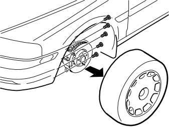
- Remove the left-hand front wheel
- Remove the five screws holding the bumper cover to the left-hand wing liner.
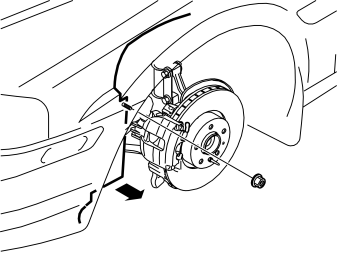
- Remove the nut holding the wing liner to the left-hand front member
- Bend the front edge of the wing liner up over the brake calliper.
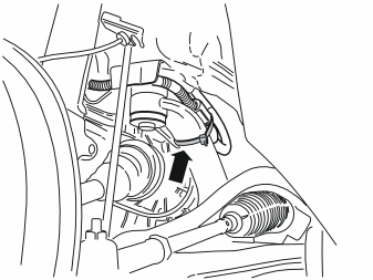
Applies to cars with only an electrical engine block
- Cut away the tie strap over the locking sleeve
- Release the cables from the front engine block heater socket from their clamps. This will make it easier to install the timer relay. If necessary, also disconnect the cable from the engine block heater
- Remove the locking sleeve over the cable junction. Pull the cables apart.
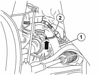
Applies to cars with an engine block heater and passenger compartment connector socket
- Release the cables from the front engine block heater socket and the engine block heater from their clamps. This makes it easier to install the timer relay
- Disconnect the clamp securing the junction connector at the stay
- Remove the junction connector and cables from the clamp and the stay.
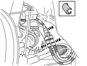
Applies to cars with an engine block heater and passenger compartment connector socket
- Remove the locking sleeves over the cable slices on the cables for the front engine block heater socket, the engine block heater and the passenger compartment connector socket
- Remove the cables from the junction connector
- Remove the holder from the junction connector. The holder must be used for the timer relay, but the junction connector will not be used again.
- Grease the O-rings on the cable for the front engine block heater socket, the timer relay and the cable to the passenger compartment connector socket (if the car has this). Use the low temperature grease (P/N 1161417-9).
Примечание: Do not get any grease on the contact surfaces of the connector.
- Take the bracket and the rubber guard from the kit (or use the existing bracket and rubber guard). Press the rubber guard on to the bracket.
Applies to cars with only an electrical engine block
- Take the screw, the toothed washer and the nut from the kit. Tighten the timer relay at the holder in the position illustrated. The holder must be parallel to the length of the timer relay
- Press the cover (1) (P/N 346509, not included) into place on the free socket in the timer relay
Applies to cars with a passenger compartment connector socket
- Take the screw, the toothed washer and the nut from the kit. Tighten the timer relay at the holder in the position illustrated. The holder must be parallel to the length of the timer relay
Illustration A
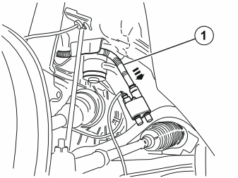
- Connect the cable (1) from the front engine block heater socket to the timer relay. Firmly press the cable junction together.
Illustration B
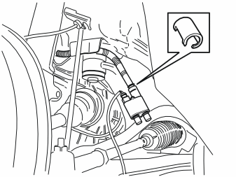
- Press the existing locking sleeve over the cable splice.
Applies to cars with only an electrical engine block Illustration A
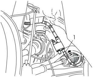
- Connect the cable (1) from the engine block heater to the timer relay. Firmly press the cable splice together.
Illustration B
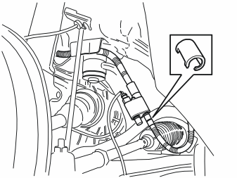
- Press a locking sleeve (from the kit) over the cable splice.
Applies to cars with an engine block heater and passenger compartment connector socketIllustration A
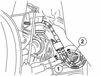
- Connect the cable (1) from the passenger compartment connector socket and the cable (2) from the engine block heater to the timer relay
- Firmly press the cable splices together.
Illustration B

- Press the locking sleeves (from the kit) over the cable splices.
Illustration A
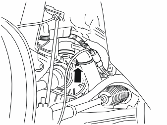
- Install the holder and the connected timer relay on the stay using the hose clamp. Ensure that the timer relay is centred on the stay and is secure. The timer relay must not slip down and be trapped by the anti-roll bar.
Illustration B
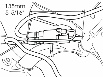
- Check that the measurements are the same as in the illustration.
- If the cables to the front engine block heater socket and the engine block heater were disconnected, reinstall them in their clamps.
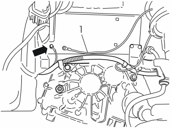
- Route the ground lead (1) from the timer relay to the ground terminal from the front engine block heater socket.
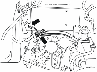
- Tighten the ground lead to the ground terminal
- Clamp the ground lead in the existing clamps. Clamp the excess cable using a tie strap from the kit.
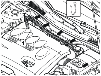
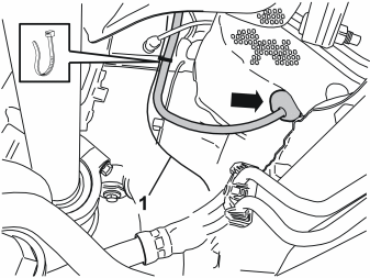
Illustrations A and B
- Route the cable (1) for the accessory electronic module (AEM) along the cable for the passenger compartment connector socket, at the top of the left-hand side of the engine compartment and across to the right-hand side. Finish by routing the cable down to the rubber grommet in the cowl panel
- Take six tie straps from the kit. Secure the cable at the existing cable.
- Open the cover for the glove compartment
- Remove the panel on the right-hand end of the dashboard. Using a weatherstrip tool, carefully pry around the panel until the three clips on the inside release.
Примечание: Do not damage the dashboard.
Applies to cars without a passenger compartment connector socket
- Fold the floor carpet to one side to access the lead-in in the cowl panel.
Applies to cars with a passenger compartment connector socket
- Remove the locking sleeve over the cable splice in the passenger compartment connector socket
- Disconnect the cable from the passenger compartment connector socket
- Remove the passenger compartment connector socket from its bracket
- Fold the floor carpet to one side to access the lead-in in the cowl panel.
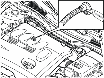
- Cut away the top of the small “rubber nipple” in the rubber grommet in the cowl panel. This is on the right-hand side of the engine compartment. Use a knife.
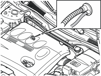
- Insert the cable for the accessory electronic module (AEM) through the rubber grommet and into the passenger compartment
- Slide all the excess cable into the passenger compartment.
- Reinstall the wing liner on the side member and bumper cover
- Reinstall the engine splash guard
- Reinstall the wheel. Tighten the wheel nuts. Tighten to 90 Nm (66 lbf.ft).
Points 47-54 apply to the V50
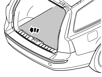
- Remove the cargo compartment carpet.
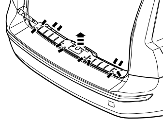
- Pry off the four external clips at the front edge/bottom edge of the sill trim panel on the tailgate
- Pry up one of the corners of the sill trim panel so that the two clips at that end release. Use a weatherstrip tool
- Pull up the sill trim panel so the remaining six clips release. Remove the panel
- Detach the rubber strip where it covers the right-hand side panel in the boot opening.
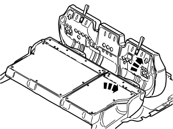
- Fold the seat cushion and backrest on the right-hand side of the rear seat forward.
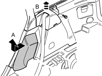
- Grasp the upper edge of the right-hand side cushion. Pull the side cushion forward so that the clip on the reverse releases
-
Slide the side cushion up. Remove the side cushion.
-
Remove the screw at the rear edge of the panel at the front/top of the right-hand side panel
- Pull the panel upwards so that the four clips on the inside release. Remove the panel.
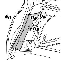
- Pull off the rubber strip at the rear of the opening for the right-hand rear door
- Carefully pry off the lower panel on the C-post on the right-hand side. Carefully pry at the top edge. Use a plastic weatherstrip tool
- Pull the panel on the C-post so that the two upper clips release. Then continue down until the last two clips release. Remove the panel on the C-post.
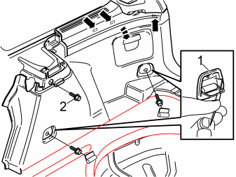
- Fold out the load securing eyelets on the right-hand side panel
- Insert a scriber with an angled tip into the holes in the top of the covers (1). Turn the scriber so that the tip engages the reverse of the cover. Pull the cover off
- Remove the screws in the load securing eyelets
- Remove the screw (2) at the front/top edge of the side panel
- Pull off the side panel at the top so that the two clips at the rear/bottom of the side window and the clip at the bottom of the D-post release
- Disconnect the connector for the 12V socket, if present
- Lift out the side panel.
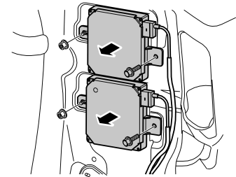
Applies to cars with reversing warning systems
- Remove the control module together with the cables for the reverse warning system. (This is done to access the accessory electronic module (AEM).)
- If necessary, also disconnect the existing surrounding cables.
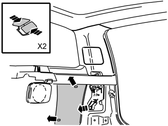
- Remove the insulation panel. The insulation panel is secured with two clips.
Points 55-62 apply to S40 (04-)
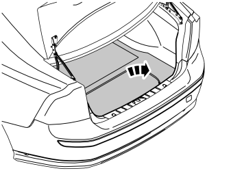
- Remove the cargo compartment carpet.
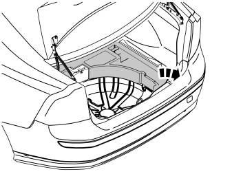
- Remove the upper floor supports on the left and right-hand sides if applicable.
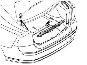
- Pry off the two external clips at the front edge/bottom edge of the sill trim panel on the boot lid
- Pry up one of the corners of the sill trim panel using a weatherstrip tool so that the two clips at that end release
- Pull up the sill trim panel at the other end so that the remaining two clips release. Remove the sill trim panel
- Detach the rubber strip where it covers the right-hand side panel in the boot opening.
- Fold the seat cushion and backrest on the right-hand side of the rear seat forward.
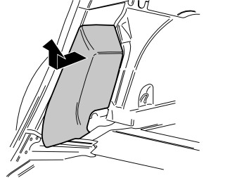
- Grasp the upper edge of the right-hand side cushion. Pull the side cushion forward so that the clip on the reverse releases
- Slide the side cushion up. Remove the side cushion.
-
Pull off the rubber strip at the rear of the opening for the right-hand rear door.
-
Carefully pry off the lower panel on the C-post on the right-hand side. Carefully pry at the top edge. Use a plastic weatherstrip tool
- Pull the panel on the C-post so that the two upper clips release. Then continue down until the last two clips release. Remove the panel on the C-post.
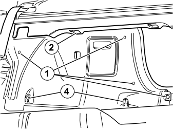
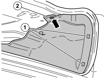
- Remove the five clips (1, illustrations A and B) holding the side panel in the bodywork
- Unhook the front edge of the parcel shelf panel at the mounting (2, illustration A). Pull the side panel away from the parcel shelf panel and the panel on the C-post
- Unhook the side panel from the mounting (3, illustration B) on the underneath of the parcel shelf
- Disconnect the connector for the 12V socket, if present
- Unhook the side panel from the load securing eyelets (4, illustration A). Remove the side panel.
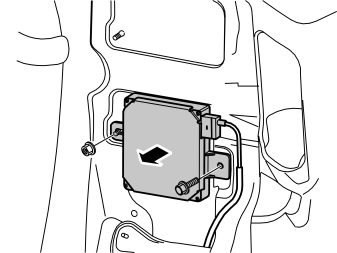
Applies to cars with reversing warning systems
- Remove the control module together with the cables for the reverse warning system. (This is done to access the accessory electronic module (AEM).)
- If necessary, also disconnect the existing surrounding cables.
Points 63-71 apply to all models
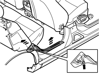
- Pull the top edge of the sill trim panel in the right-hand rear door inwards until the clips on the inside release. Then continue down and pull the panel upwards until the remaining two clips on the underside release.
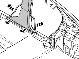
- Pull off the rubber mouldings at the rear edge of the right-hand front door and at the front edge of the right-hand rear door. This releases the lower panel on the B-post
- Pull the bottom edge of the lower panel on the B-post until the two bottom clips release.
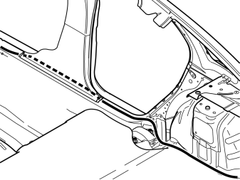
- Route the cable to the accessory electronic module (AEM) from the rubber grommet in the cowl panel
- Route the cable inside the floor carpets, the lower panel on the B-post and the insulation panels, back to the accessory electronic module (AEM) inside the panel in the rear edge of the right-hand rear wheel arch. Route the cable along the existing cable harnesses in the cargo compartment, between the floor support and the bodywork.
Примечание: Ensure that the cable is positioned so that there is no risk of it catching or rubbing.
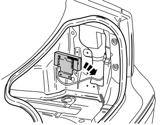
- Pull the accessory electronic module (AEM) away from its bracket in the rear edge of the right-hand rear wheel arch.
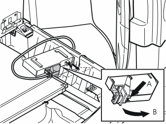
- Disconnect the large connector from the accessory electronic module (AEM). First press in the catch (A). Pull the black locking handle (B) in the direction of the arrow until a click is heard
- Disconnect the connector from the accessory electronic module.
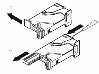
- Remove the black catch holding the black switch in place in the connector by pulling in the direction of the arrow
- Remove the black switch by inserting a pointed object in the hole on the other shorter side. Press the switch out.
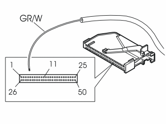
- Connect the red (R) cable from the routed cable harness to terminal 5 in the black connector for the accessory electronic module (AEM).
Примечание: The numerical markings on the top and bottom of the black terminal pin are extremely small, so be careful when installing the cable.
- Reinstall the black switch in the connector. Lock into place using the catch
- Press the connector into the accessory electronic module (AEM). Secure using the black locking handle
- Reinstall the accessory electronic module (AEM) in its bracket.
- Reinstall the control module for the reverse warning system, if present. Also reinstall any cables that were disconnected
- Reinstall the insulation panel in the right-hand rear wheel housing (applies to the V50)
- Reinstall the side panel in the cargo compartment
- Tighten the screws for the load securing eyelets. Tighten to 24 Nm (18 lbf.ft.) (applies to the V50)
- Reinstall the rubber strip in the boot lid opening
- Reinstall the sill trim panel for the tailgate/boot lid
- Reinstall the upper floor supports if applicable (applies to the P11)
- Reinstall the cargo compartment carpet
- Reinstall the sill trim panel in the right-hand rear door
- Reinstall the lower C-post panel
- Reinstall the side cushion
- Press the lower panel on the B-post into place. Reinstall the rubber mouldings in the door openings
- Fold the backrest and seat cushion back into place
- Fold the floor carpet on the front right-hand side back into position
- Reinstall and connect the passenger compartment connector socket, if present
- Reinstall the sill trim panel in the right-hand front door
- Reinstall the panel on the right-hand end of the dashboard.
- Program the function using VCT2000 in VIDA.
Обсуждение и оценка
0Пока нет комментариев. Будьте первым.