Применимость
| Модель | Двигатель | Год |
|---|---|---|
| S40 (04-) | — | 2004–2009 |
| V50 | — | 2004–2009 |
Примечание: Cut-off point for cars built before and after week 46, 2004 (w446) with RTI.
Примечание: Explanation of kit illustration
- A Always required
- B Required for cars without RTI andEU cars with RTI, built after w446
- C Required forall cars with RTI, built before w446US cars with RTI, built after w446
- D and E always required in S40
- F required in S40 with low cargo compartment floor
- G always required in V50
- H required in V50 with low cargo compartment floor
Примечание: This accessory is connected to the car's electrical system. It requires software unique to the car.
Steps 1-27 apply to the S40
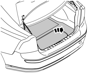
- Turn the ignition switch to position 0.
- Remove the cargo compartment carpet.
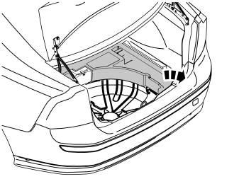
Applies to cars with a high cargo compartment floor
- Remove the upper floor supports on the right and left-hand sides
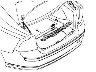
Removing the sill trim panel from the boot lid:
- Unscrew the two external clips at the front edge/bottom edge of the sill trim panel on the boot lid.
- Pry up one of the corners of the sill trim panel using a weatherstrip tool so that the two clips at that end release.
- Pull up the sill trim panel at the other end so that the remaining two clips release. Remove the sill trim panel.
- Remove the rubber strip from the boot lid opening where it covers the side panels on the left and right-hand sides.
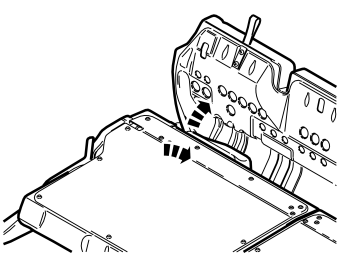
- Fold forward the seat cushions and backrests on both sides of the rear seat.
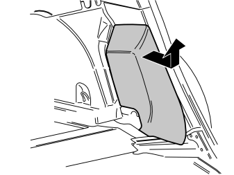
Removing the side cushion:
- Grasp the upper edge of the left-hand side cushion. Pull the side cushion forward so that the clip on the reverse releases.
- Slide the side cushion upwards.
- Remove the right-hand side cushion in the same way.
Illustration A
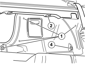
Removing the side panels:
- Remove the five clips (1, illustrations A and B) holding the left-hand side panel in the bodywork.
- Unhook the front edge of the parcel shelf panel at the mounting (2, illustration A). Pull the side panel away from the parcel shelf panel and the panel on the C-post.
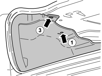
- Unhook the side panel from the mounting (3, illustration B) on the underneath of the parcel shelf.
- Unhook the side panel from the load securing eyelet (4, illustration A). Remove the side panel.
- Remove the right-hand side panel in the same way.
Illustration B
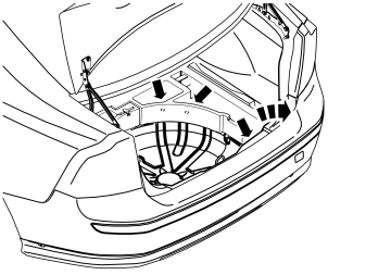
- Remove the floor supports on the right and left-hand sides. First unscrew the three clips in the bottom of the compartments. Then lift out the floor supports.
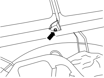
- Remove the screw in the bracket for the rear seat backrest.
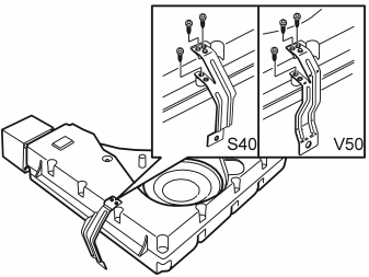
- Turn the subwoofer so that the front of the loudspeaker is facing up.
- Take three screws from the kit and install the bracket for the S40 on the subwoofer as illustrated.
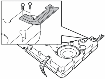
- Take two screws from the kit. Install the front bracket on the subwoofer.
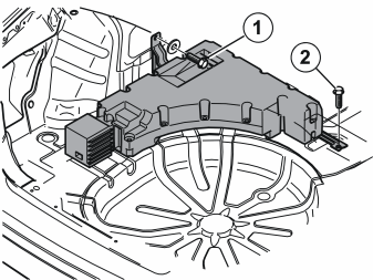
- Position the subwoofer in the left-hand side of the cargo compartment.
- Take the M8x24 screw (1) and washer from the kit. Install the screw and washer in the left-hand bracket.
- Take the screw (2) from the bracket for the backrests. Install the screw in the right-hand bracket for the subwoofer.
- Tighten the M10 screw. Tighten to 50 Nm (37 lbf. ft.).
- Tighten the M8 screw. Tighten to 24 Nm (18 lbf. ft.).
Connecting fibre optic cables
Примечание: Cars without RTI
- see steps 13-14
US cars with RTI
- see steps 15-17
EU cars with RTI
- built before w446, see steps 15-17
- built after w446, see steps 18-19
Steps 13-14 apply to cars without RTI
Illustration A
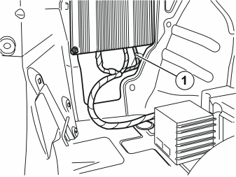
- Disconnect the fibre optic cable (1) from the underside of the amplifier.
Illustration B
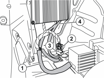
- Take the T-fibre optic cable (B in the kit illustration) from the kit. Connect the long end (1) to the subwoofer.
- Connect the connector (2), which was disconnected from the amplifier, to the female terminal (3) on the T-fibre optic cable.
- Connect the remaining connector (4) on the T-fibre optic cable to the amplifier.
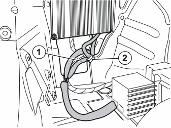
- Secure the cable splice terminals to the fibre optic cables (1) using the clip (2) for the panel edge.
Примечание: Do not bend the fibre optic cable too tightly.
- Check the bend radius of the fibre optic cables. If the bend radius is less than 25 mm (1”), remove the tape from the thick cable harness and increase the radius.
- Continue to point Connecting the power supply cable.
Steps 15-17 apply to US cars with RTI, and EU cars with RTI built before w446
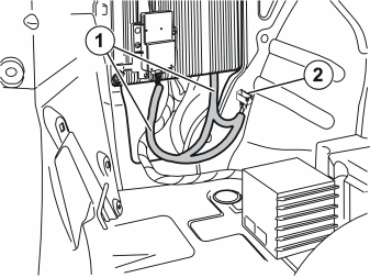
- Disconnect the fibre optic cables (1) from the GPS antenna and the underside of the amplifier.
- Separate the connectors at the join of the fibre optic cables (2).
- Place the T-fibre optic cable, which is completely disconnected, to one side (there is a new fibre optic cable in the kit).
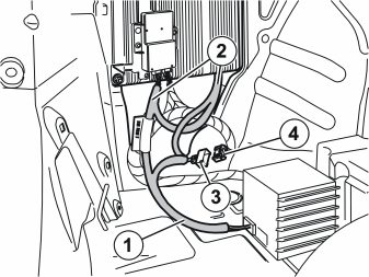
- Take the adapter fibre optic cable (C in the kit illustration) from the kit. Connect the long end (1) to the subwoofer.
- Connect the male connectors (2) of the adapter fibre optic cable to the amplifier and GPS antenna.
Примечание: The end equipped with the label must be connected to the GPS antenna.
- Connect the female connector (3) of the adapter fibre optic cable to the connector (4) on the fibre optic cable that was disconnected from the removed T-fibre optic cable.
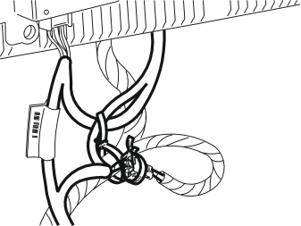
- Take a double tie strap from the kit. Secure the cable splice terminals for the fibre optic cable harness at the existing cable harness.
Примечание: Do not bend the fibre optic cable too tightly.
- Check the bend radius of the fibre optic cables. If the bend radius is less than 25 mm (1"), remove the tape from the thick cable harness and increase the radius.
- Continue to point Connecting the power supply cable.
Steps 18-19 apply to EU cars with RTI, built after w446
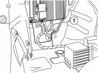
- Disconnect the fibre optic cable (1) from the underside of the amplifier.
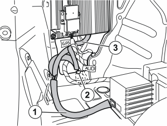
- Take the T-fibre optic cable (B in the kit illustration) from the kit. Connect the long end (1) to the subwoofer.
- Connect the female connector of the adapter fibre optic cable to the connector on the fibre optic cable that was disconnected from the amplifier.
- Connect the male connector (3) of the adapter fibre optic cable to the amplifier.
- Secure the cable splice terminals to the fibre optic cables using the clip (2) for the panel edge.
Примечание: Do not bend the fibre optic cable too tightly.
- Check the bend radius of the fibre optic cables. If the bend radius is less than 25 mm (1”), remove the tape from the thick cable harness and increase the radius.
Connecting the power supply cable
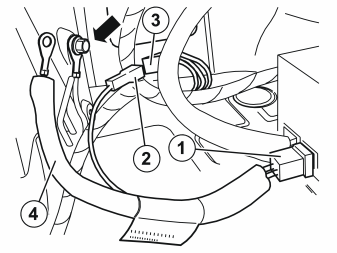
- Take the power supply cable (A in the kit illustration) from the kit. Connect the power supply cable to the subwoofer:
- Tighten the ground terminal securely.
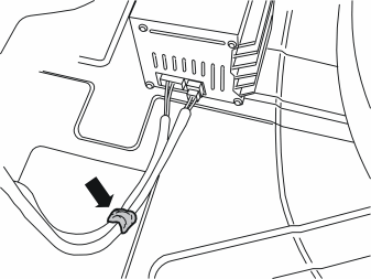
- Using butyl tape, tape the cables for the subwoofer to the floor and straight back approximately 200 mm (7 7/8”). The cables must be positioned in the cut-out on the underside of the floor support when this is installed.
Illustration A
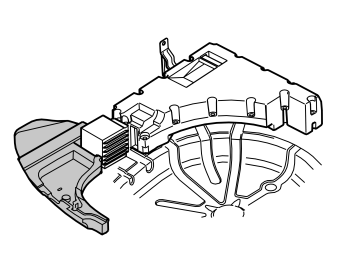
- Take the left-hand small floor support from the kit and fit it in the rear left-hand corner of the cargo compartment.
Illustration B
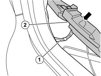
- Ensure that the cables (1) for the subwoofer are positioned in the cut-out (2) on the underside of the floor support so that they are not trapped against the lower floor in the cargo compartment.
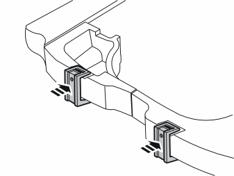
Applies to cars with grocery bag holder on the cargo compartment floor
- Press in an adapter on the left and right-hand upper floor supports according to the existing marking as illustrated.
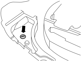
- Press the floor support into place using the existing clip.
- Transfer the towing eyelet to the new floor support.
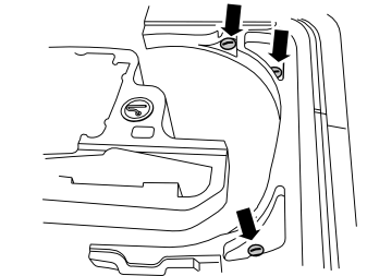
- Reinstall the right-hand lower floor support using the existing clips.
- Reinstall the side panels using the existing clips.
- Reinstall the rubber strip on the sides in the boot lid opening.
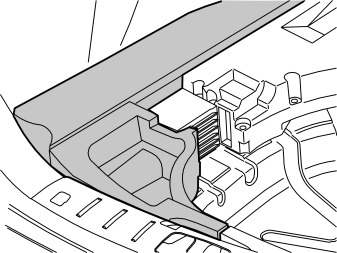
- Reinstall the sill trim panel in the boot lid opening using the existing clips.
- Take the left-hand upper floor support (E in the kit illustration) from the kit. Install the floor support.
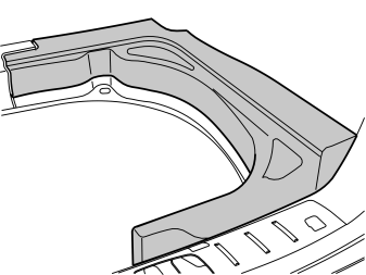
Applies to cars with a low cargo compartment floor
- Take the right-hand upper floor support (F in the kit illustration) from the kit. Install the floor support.
- Reinstall the side cushions
- Take the new, wider cargo compartment carpet from the kit. Install the carpet.
Applies to cars with a high cargo compartment floor
- Reinstall the right-hand upper floor support.
- Reinstall the side cushions.
- Reinstall the cargo compartment carpet.
Applies to all models
- Fold the backrests and the seat cushions back into place.
- Program the function.
Steps 28-57 apply to the V50
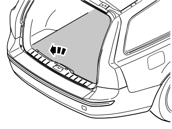
- Turn the ignition switch to position 0.
- Remove the cargo compartment carpet.
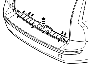
Removing the sill trim panel from the tailgate:
- Pry off the four external clips at the front edge/bottom edge of the sill trim panel on the tailgate.
- Pry up one of the corners of the sill trim panel using a weatherstrip tool so that the two clips at that end release.
- Pull up the sill trim panel so the remaining six clips release. Remove the panel.
- Remove the rubber strip from the tailgate opening where it covers the side panels on the left and right-hand sides.
- Fold forward the seat cushions and backrests on both sides of the rear seat.
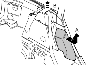
Removing the side cushion:
- Grasp the upper edge of the left-hand side cushion (A). Pull the side cushion forward so that the clip on the reverse releases.
- Slide the side cushion upwards.
- Remove the right-hand side cushion in the same way.
Removing the panels:
- Remove the screw at the rear edge of the panel (B) at the front/top of the left-hand side panel.
- Pull the panel upwards so that the four clips on the inside release.
- Remove the panel by the right-hand side panel in the same way.
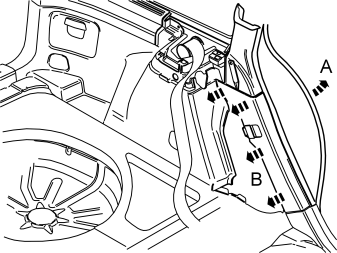
- Remove the rubber strip (A) at the rear edge of the rear door opening on the left and right-hand sides.
Removing the lower panels on the C-post:
- Carefully pry off the lower panel (B) on the left-hand C-post at the top edge. Use a plastic weatherstrip tool.
- Pull the C-post panel downwards until all four clips have released.
- Remove the lower panel on the right-hand C-post in the same way.
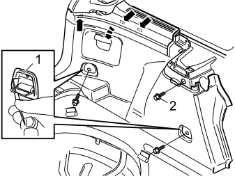
Removing the side panels:
- Fold out the load securing eyelets on the left-hand side panel.
- Insert a scriber with an angled tip into the holes in the top of the covers (1). Turn the scriber so that the tip engages the reverse of the cover. Pull the cover off.
- Remove the two screws from the load securing eyelets.
- Remove the screw (2) at the front/top edge of the side panel.
- Pull off the side panel at the top so that the two clips at the rear/bottom of the side window and the clip at the bottom of the D-post release.
- Lift out the side panel.
- Remove the right-hand side panel in the same way.
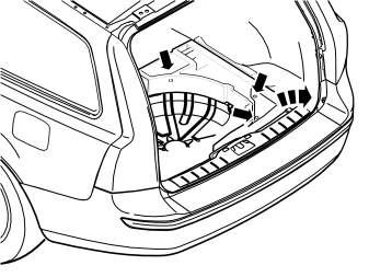
- Remove the floor supports on the right and left-hand sides. First unscrew the three clips in the bottom of the compartments and then lift out the floor supports.
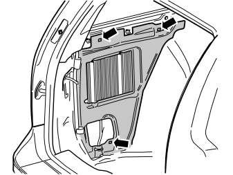
- Remove the insulation panel around the amplifier. First remove the three clips.
- Remove the screw in the bracket for the rear seat backrest.
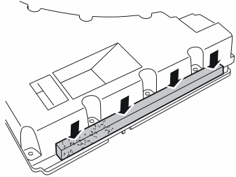
- Remove the foam piece from the kit. Remove the backing.
- Press the foam piece into place along the right-hand edge at the top of the subwoofer.
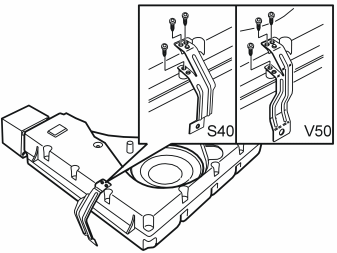
- Turn the subwoofer so that the front of the loudspeaker is facing up.
- Take three screws from the kit and install the bracket for the V50 on the subwoofer as illustrated.
- Take two screws from the kit. Install the front bracket on the subwoofer.
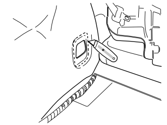
- Using a utility knife, cut out the front insulation panel along the existing markings.
- Position the subwoofer in the left-hand side of the cargo compartment.
- Take the screw (2) for the bracket for the backrests. Install the screw in the right-hand bracket for the subwoofer.
- Tighten the screw. Tighten to 50 Nm (37 lbf. ft.).
- Screw (1) is common with the load securing eyelet. Fitted at point en-GB0900c8af8233a5a7#KC08861505.
Connecting fibre optic cables
Примечание: Cars without RTI
- see steps 43-44
US cars with RTI
- see steps 45-47
EU cars with RTI
- built before w446, see steps 45-47
- built after w446, see steps 48-49
Steps 43-44 apply to cars without RTI
Illustration A
- Disconnect the fibre optic cable (1) from the underside of the amplifier.
Illustration B
- Take the T-fibre optic cable (B in the kit illustration) from the kit. Connect the long end (1) to the subwoofer.
- Connect the connector (2), which was disconnected from the amplifier, to the female terminal (3) on the T-fibre optic cable.
- Connect the remaining connector (4) on the T-fibre optic cable to the amplifier.
- Secure the cable splice terminals to the fibre optic cables (1) using the clip (2) for the panel edge.
Примечание: Do not bend the fibre optic cable too tightly.
- Check the bend radius of the fibre optic cables. If the bend radius is less than 25 mm (1”), remove the tape from the thick cable harness and increase the radius.
- Continue to point Connecting the power supply cable.
Steps 45-47 apply to US cars with RTI, and EU cars with RTI built before w446
- Disconnect the fibre optic cables (1) from the GPS antenna and the underside of the amplifier.
- Separate the connectors at the join of the fibre optic cables (2).
- Place the T-fibre optic cable, which is completely disconnected, to one side (there is a new fibre optic cable in the kit).
- Take the adapter fibre optic cable (C in the kit illustration) from the kit. Connect the long end (1) to the subwoofer.
- Connect the male connectors (2) of the adapter fibre optic cable to the amplifier and GPS antenna.
Примечание: The end equipped with the label must be connected to the GPS antenna.
- Connect the female connector (3) of the adapter fibre optic cable to the connector (4) on the fibre optic cable that was disconnected from the removed T-fibre optic cable.
- Take a double tie strap from the kit. Secure the cable splice terminals for the fibre optic cable harness at the existing cable harness.
Примечание: Do not bend the fibre optic cable too tightly.
- Check the bend radius of the fibre optic cables. If the bend radius is less than 25 mm (1"), remove the tape from the thick cable harness and increase the radius.
- Continue to point Connecting the power supply cable.
Steps 48-49 apply to EU cars with RTI, built after w446
- Disconnect the fibre optic cable (1) from the underside of the amplifier.
- Take the T-fibre optic cable (B in the kit illustration) from the kit. Connect the long end (1) to the subwoofer.
- Connect the female connector of the adapter fibre optic cable to the connector on the fibre optic cable that was disconnected from the amplifier.
- Connect the male connector (3) of the adapter fibre optic cable to the amplifier.
- Secure the cable splice terminals to the fibre optic cables using the clip (2) for the panel edge.
Примечание: Do not bend the fibre optic cable too tightly.
- Check the bend radius of the fibre optic cables. If the bend radius is less than 25 mm (1”), remove the tape from the thick cable harness and increase the radius.
Connecting the power supply cable
- Take the power supply cable (A in the kit illustration) from the kit. Connect the power supply cable to the subwoofer:
- Tighten the ground terminal securely.
- Using butyl tape, tape the cables for the subwoofer to the floor and straight back approximately 200 mm (7 7/8”). The cables must be positioned in the cut-out on the underside of the floor support when this is installed.
Illustration A
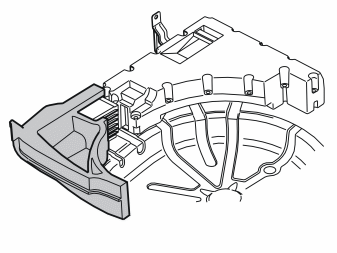
- Take the left-hand small floor support from the kit and fit it in the rear left-hand corner of the cargo compartment.
Illustration B
- Ensure that the cables (1) for the subwoofer are positioned in the cut-out (2) on the underside of the floor support so that they are not trapped against the lower floor in the cargo compartment.
- Press the floor support into place using the existing clip.
- Transfer the towing eyelet to the new floor support.
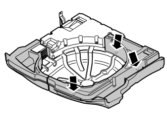
Applies to cars with a low cargo compartment floor
- Take the right-hand floor support (H in the kit illustration) from the kit. Install the floor support using the existing clips. (The old floor support will not be used again.).
For cars with a high cargo compartment floor
- Reinstall the right-hand floor support.
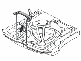
Applies to cars with grocery bag holder on the cargo compartment floor
- Install the adapter in the socket intended in the floor support.
Reinstall:
- the insulation panel
- the side panels. Tighten using the screw at the front edge. Tighten the screws for the load securing eyelets. Tighten to 24 Nm (18 lbf.ft.). The screw is the same screw as that for the subwoofer rear mounting.
- the covers for the load securing eyelets.
- the lower panels on the C-post
- the rubber strip at the rear edge of the opening for the rear doors
- the panels at the front/top of the side panels. Press downwards so that the catches engage. Tighten using the screw
- the side cushions
- the rubber strip on the sides in the tailgate opening
- the sill trim panel for the tailgate.
- Reinstall the cargo compartment carpet.
- Fold the backrests and seat cushions back into place.
- Program the function.
Обсуждение и оценка
0Пока нет комментариев. Будьте первым.