Preparations
- Make a note of the radio code if an anti-theft coded radio is installed.
- Turn the ignition key to position 0.
- Disconnect the battery negative lead.
- Remove the right indicator.
- Jack up the car at the front right side.
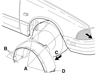
- Remove the right wheel arch completely: 3 plugs (A), 3 screws (B), screw (C) and screw (D).
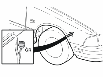
Примечание: Some variants have a pre-routed alarm cable harness in the engine compartment. If this is the case, there is a 6-pin grey (GR) connector under the right front wing taped on the cable harness.
Cars with a grey (GR) connector
- Remove the tape and go to step 11.
Cars without a grey (GR) connector
- Install the extra alarm cable harness in the engine compartment. See steps 3-10.
Engine compartment, cable routing and connecting
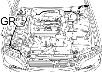
- Lead the extra alarm cable harness from the underside front wing, through the inner wing to the engine compartment.
- Position the extra alarm cable harness in the engine compartment and ensure it with tie-straps.
- Remove the lower panel and the sound isolation under the dashboard on the driver side.
- Disconnect the courtesy lighting wiring.
- Remove the rubber grommet from the accessory hole.
- Pass the extra alarm cable harness through the accessory hole to the passenger compartment.
- Install the rubber grommet.
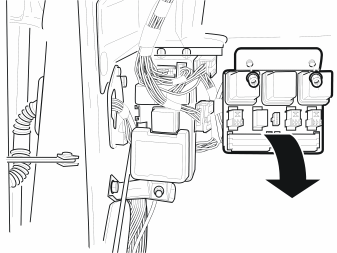
- Remove the two nuts.
- Turn the relay box aside.
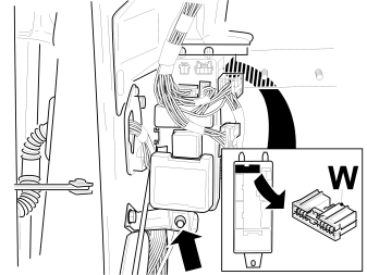
- Unhook the cable from the hood catch.
- Remove the nut and carefully pull down the fuse box.
- Turn the fuse box so that the white (W) 20-pin connector on the rear can be disconnected.
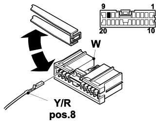
- Unlock the connector.
- Bring the yellow/red (Y/R) wire in position 8.
- Lock the connector.
- Connect the 20-pin connector to the fuse box.
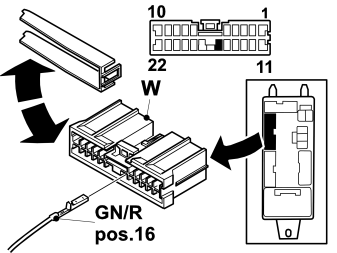
- Disconnect the white (W) 22-pin connector from the rear side of the fuse box.
- Unlock the connector.
- Bring the green/red (GN/R) wire in position 16.
- Lock the connector.
- Connect the 22-pin connector to the fuse box.
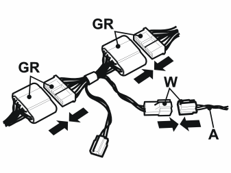
- Locate the grey (GR) 22-pin connector. (It is located behind the fuse box in the upper corner).
- Disconnect the connector and place the extra accessory connector between.
- Connect the white (W) 4-pin connector (A) from the extra alarm cable harness engine compartment.
- Install the connectors in the upper corner.
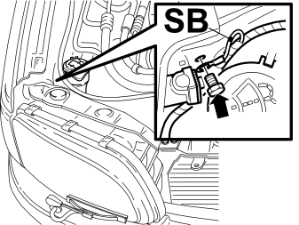
- Connect the black (SB) cable to ground at the right head lamp, tighten to 10 Nm (8 lbf ft).
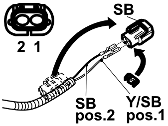
- Remove the tape and remove the black (SB) 2-pin connector from the extra alarm cable harness engine compartment.
- Remove the connector locking.
- Bring the yellow/black (Y/SB) wire in position 1.
- Bring the black (SB) wire in position 2.
- Install the connector locking.
Installing the siren
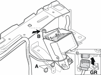
- Clean the contacts of the grey (GR) connector if necessary.
Примечание: Use grease in the connector (p/n 1161427).
- Connect the connector and position the siren in the body (B) with the rubber plug.
- Install the bolts (A) and tighten to 10 Nm (8 lbf ft).
- Install the wheel arch and the right indicator.
Replacing the bonnet lock
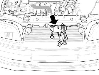
- Remove the three bonnet lock bolts. (They will no longer be used).
- Unlock the cable from the bonnet lock.
- Remove the bonnet lock.
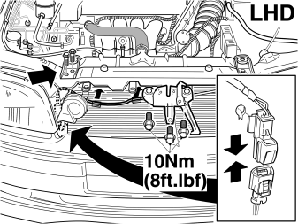
Cars without A/C
- Hook the cable in the new bonnet lock.
- Position the new bonnet lock and install three new bolts, tighten to 10 Nm (8 lbf ft).(Use the new bolts from the set.)
- Remove the radiator bracket on the right side. (In order to facilitate the passage of the bonnet switch connector.)
- Locate the black (SB) 2-pin connector of the bonnet switch on the inside of the front section.
- Connect the connector and fit it to the front section.
- Press the cable harness with the clips into the front section.
- Install the radiator bracket and bolts, tighten to 25 Nm (18 lbf ft).
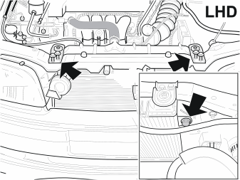
Cars with A/C
- Remove the radiator brackets on the left and right sides.
- Remove the left and right condenser bolts on the inside of the front section.
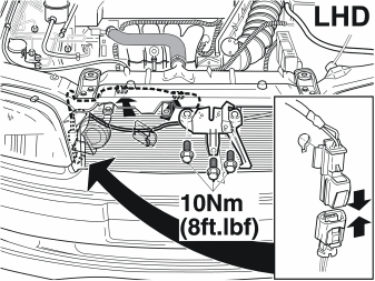
Cars with A/C
- Hook the cable in the new bonnet lock.
- Position the new bonnet lock and install three new bolts, tighten to 10 Nm (8 lbf ft). (Use the new bolts from the set.)
- Locate the black (SB) 2-pin connector of the bonnet switch on the inside of the front section.
- Carefully push the radiator and condenser towards the engine and press the cable harness with the clips into the front section.
- Install the two condenser bolts, tighten to 10 Nm (8 lbf ft).
- Install the radiator brackets and bolts, tighten to 25 Nm (18 lbf ft).
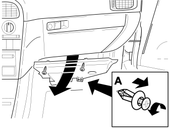
- Remove the screws and clip (A).
- Remove the lower panel on the passenger side.
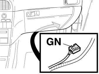
Примечание: Some variants have a pre-routed alarm cable harness in the dashboard. If this is the case, there is a green (GN) 5-pin connector taped back on the cable harness dashboard (next to the blower motor on the passenger side).
Cars with a green (GN), 5-pin connector
- Go to step 35.
Cars without a green (GN), 5-pin connector
- Install the extra alarm cable harness in the dashboard. See steps 18-34.
Dashboard, cable routing and connecting
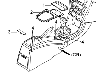
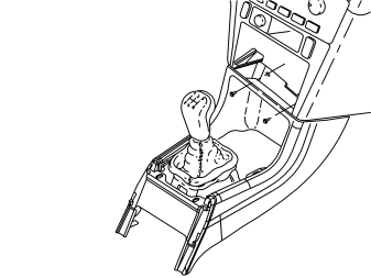
Figure 18A
- Remove the rubber pad (1).
- Remove the gear lever panel (2) by pressing in the tabs and removing it. (Manual gearboxes only: Push the clips in and remove the sleeve.)
- Apply the parking brake fully.
- Remove the cover (3) and the four screws (4).
- Disconnect the grey (GR) connector. Pull up the front side of the rear centre console.
- Remove the rear console completely.
Figure 18B
- Remove the two screws at the front.
- Remove the complete front centre console with a turning movement.
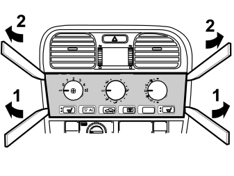
- 1: Carefully position special tool (p/n 9814071) between the dashboard and the underside of the heater panel. Pull the bottom of the heater panel towards you.
- 2: Press the entire panel slightly upwards and carefully pull it towards you from the top. Remove the panel.
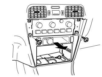
- Remove the three screws holding the centre console.
- If applicable: disconnect the connectors.
- Remove the console.
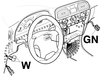
- If needed: Remove the lower panel and the sound isolation under the dashboard.
- Disconnect the courtesy lighting wiring.
- Position the extra cable harness in the dashboard as illustrated.
- Ensure that the cable harness is well secured with tie straps.
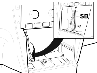
- Connect the black (SB) cable to ground as illustrated.
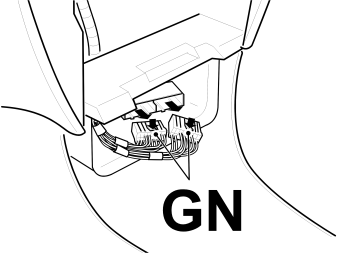
- Push the locking in and remove the green (GN) connectors from the alarm module.
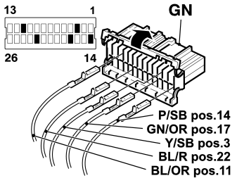
- Open the green (GN) 26-pin connector.
- Bring the yellow/black (Y/SB) wire in position 3.
- Bring the blue/orange (BL/OR) wire in position 11.
Примечание: If there already is a blue/orange (BL/OR) wire in position 11, tape the blue/orange (BL/OR) wire from the extra cable harness dashboard back (this wire will not be used).
- Bring the pink/black (P/SB) wire in position 14.
- Bring the green/orange (GN/OR) wire in position 17.
- Bring the blue/red (BL/R) wire in position 22.
- Install the connector locking.
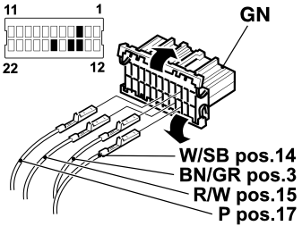
- Open the green (GN) 22-pin connector.
- Bring the brown/grey (BN/GR) wire in position 3.
- Bring the white/black (W/SB) wire in position 14.
- Bring the red/white (R/W) wire in position 15.
- Bring the pink (P) wire in position 17.
- Install the connector locking and reconnect the 22-pin and 26-pin connector to the alarm module.
- Remove the two nuts from the relay box.
- Turn the relay box so that the rear side is visible.
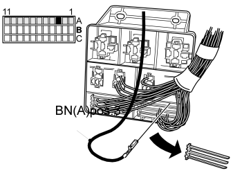
- Remove the locking.
- Connect the brown (BN) cable to terminal 3 in distribution strip A.
- Reinstall the locking.
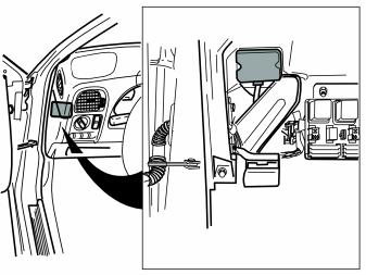
- Push the locking in and remove the green (GN) 10-pin connector from the immobilizer unit.
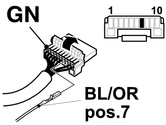
- Open the green (GN) 10-pin connector.
- Bring the blue/orange (BL/OR) wire in position 7.
Примечание: If there already is a blue/orange (BL/OR) wire in position 7, tape the blue/orange (BL/OR) wire from the extra cable harness dashboard back (this wire will not be used).
- Install the connector locking and reconnect the connector to the immobilizer unit.
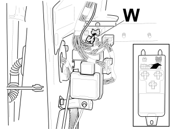
- Connect the white (W) 6-pin connector to the front of the relay box.
For cars with a pre-routed alarm cable harness engine compartment, see step 32 and 33.
If the car is prepared with the extra alarm cable harness engine compartment, go to step 34.
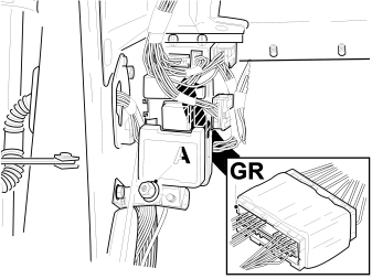
- Unhook the cable from the hood catch.
- Remove the nut (A) and carefully pull down the fuse box.
- Twist the fuse box to one side and locate the grey (GR) 22-pin connector. (It is located behind the fuse box in the upper corner).
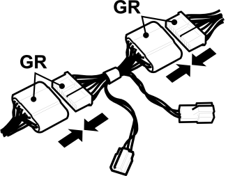
- Disconnect the grey (GR) connector and place the extra accessory connector between.
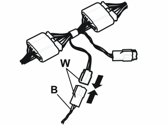
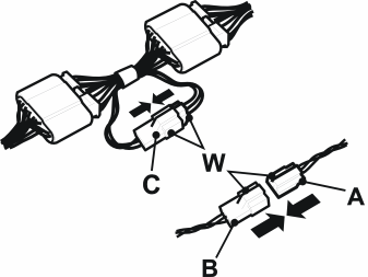
Figure 34ACars prepared with the extra alarm cable harness dashboard
- Connect the white (W) 4-pin connector (B) from the extra alarm cable harness dashboard.
- Install the connectors in the upper corner.
Figure 34BCars prepared with the extra alarm cable harness dashboard and the extra alarm cable harness engine compartment
- Connect the white (W) 4-pin connector (B) from the extra alarm cable harness dashboard to the white (W) 4-pin connector (A) from the extra alarm cable harness engine compartment.
- Connect the white (W) 4-pin extra accessory connectors (C).
- Install the connectors in the upper corner.
Finishing work
- Re-install the removed components.
- Check the function of the bonnet lock.
- Turn the ignition key to position II.
- Ensure that nobody is in the car.
- Connect the battery negative lead.
- If applicable: Enter the radio code.
- Readjust the clock.
- Program the software, using VIDA service information.
- Check the proper functioning according to the service manual.
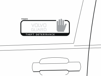
- Affix the stickers to the glass window panes of the front doors.
Обсуждение и оценка
0Пока нет комментариев. Будьте первым.