Примечание: During installation the underlay must be kept at a temperature of at least +15°C (60°F).
- Turn the ignition key to position 0
- Remove the ignition key from the ignition switch
- Clean the bumper. Use a mild soap solution.
Примечание: Wait at least five minutes before disassembling the connectors or removing other electrical equipment.
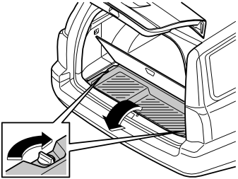
- Remove the rear floor hatch. Open the rear floor hatch and pull it straight backwards
- Place the floor hatch to one side
- Turn the knobs on the left and right-hand sides of the storage box. Lift out the storage box.
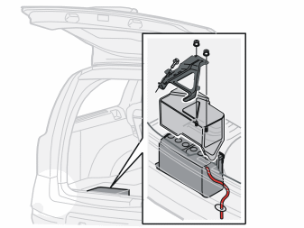
- Remove the two nuts from the front edge of the battery holder. Remove the cover over the battery Then unscrew the screw in the rear edge a few turns. Remove the holder
- Remove the cover
- Disconnect the battery negative lead.
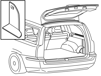
- Remove the folding panel from the right-hand side in the cargo compartment.
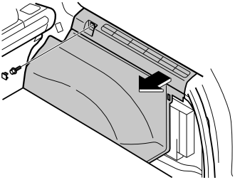
- Remove the right-hand side panel. First remove the cover and the screw at the front edge
- Pull the top edge of the panel out until the clips release
- Fold the panel in. Remove the panel.
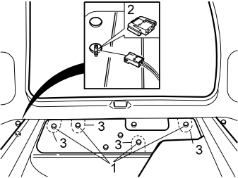
Applies to cars with lining mats with four perforations
- Remove the perforated sections (3) from the lining mat.
Applies to cars with lining mats with one perforation
- Remove the lining mat.
Applies to all cars
- Remove the four nuts (1) in the rear crossmember. This allows the bumper to be removed
- Separate the connector (2) for the antenna.
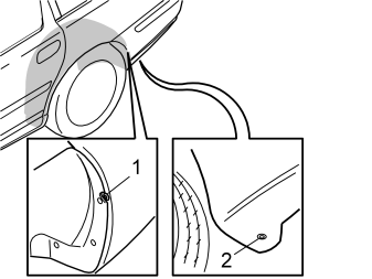
- Unscrew the screw (1) on the left and right hand sides in the rear edge of the wheel arch. Screw the screw almost entirely out
- Press the screw using a screwdriver until the loose end pieces on the inside of the bumper cover are pressed backwards
- Drill out the blind rivet (2) securing the bumper cover at the rear lower edge of the wheel arch on the left and right-hand sides.
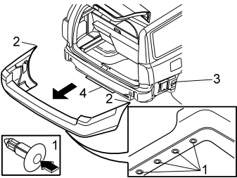
- Remove the four clips (1) at the bottom edge of the bumper cover. Press in the centre of the clips until they click
- Pull the bumper backwards slightly. Bend out the sides (2) so that they detach from the mounting (3). Then pull the bumper backwards until it detaches completely
- Place the bumper on an underlay that will not damage the paint
- Carefully remove the moulding (4) from the expander clips.
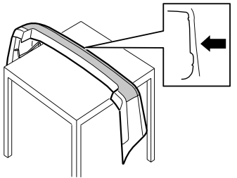
- Clean the outside of the bumper
- Install the backing paper evenly distributed over the bumper.
Примечание: The backing paper is used to protect the paint.
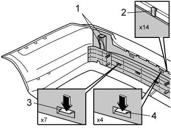
- Remove the four catches (1) from the upper edge of the bumper on the left and right-hand sides
- Release the fourteen catches (2) from the upper edge of the bumper
- Remove the seven catches (3) from the centre of the bumper
- Release the four catches (4) from the upper edge of the bumper
- Remove the foam and the bumper rail from the bumper cover.
Примечание: Do not remove the antenna from the foam.
- Clean the inside of the bumper.
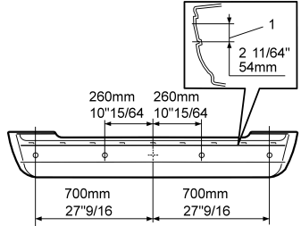
- Find the centre of the bumper cover. The centre is marked with two marks "+". One on each side of the embossing in the inside of the bumper cover. Start from the upper "+". marking when measuring the three horizontal distances. For vertical measurement (1), measure from the upper side of the embossing. Make a mark at 5 mm (2 11/64”) upwards
- Make marks to drill the four holes as illustrated.
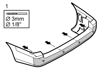
- Pre-drill the four Ø3 mm (1/8”) diameter holes at the markings. Drill from the inside of the bumper cover.
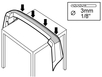
- Install the foam and the bumper rail in the bumper cover
- Drill through the bumper cover, the foam and the bumper rail. Use a Ø3 mm (1/8”) diameter drill bit in the pre-drilled holes. This is to make a mark so that the holes for the sensor holder, sensor and connector can be drilled
- Remove the bumper rail and foam from the bumper cover.
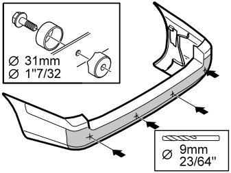
- Drill out the bumper cover. Use a Ø9 mm (23/64”) diameter drill bit
- Open the hole in the bumper casing. Use a Ø31 mm (1 7/32”) diameter hole cutter (P/N 9814069).
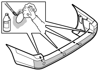
- Wash away any stones and dirt near the holes from the inside of the bumper casing. Use a mild soap solution
- Clean around the drilled hole using a cleaning pads (P/N 9192678). Allow to dry
- Apply primer (P/N 9192679) around the holes. Allow to dry.
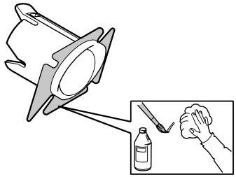
- Clean the mating surface on the sensor holders using cleaning pads (P/N 9192678). Allow to dry
- Apply primer (P/N 9192679) to the cleaned surfaces of the sensor holders. Allow to dry.
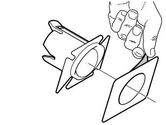
- Remove the yellow protective film from one side of the tape
- Secure the tape on the sensor holder
- Carry out the above procedure on the remaining three sensor holders.
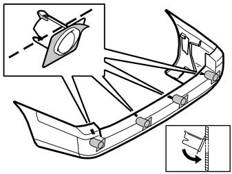
- Remove the protective film from the orange pieces of tape on the sensor holders
- Install the holders for the sensors. The narrow side must be pointing upward. Install horizontally in line with the bumper casing, as illustrated.
Примечание: The tape adheres immediately.
Осторожно: Incorrect positioning of the sensors may result in partial or complete malfunction.
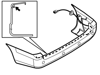
- Clean the inside of the bumper where the cable harness will be secured. Use primer (P/N 9192679)
- Secure the cable harness using butyl tape.
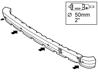
- Remove the foam from the bumper rail
- Drill through the pre-drilled holes in the foam. Use a Ø50 mm (2”) diameter hole saw
- Reinstall the foam in the bumper cover.
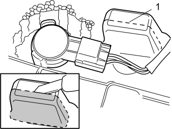
A cut out for the right sensor must be made in a guide (1) in the foam. This is so that the connector can be connected.
- Cut out enough so that the connector can be connected to the sensor. Use a knife
- Install the right sensor with the connector. Test
- Leave the sensor with the connector in place.
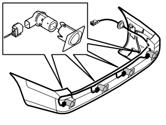
- Connect the cable harness connectors to the sensors.
Примечание: A click should be heard when connecting. The noise confirms that the catch has locked.
- Install the sensors in the holders.
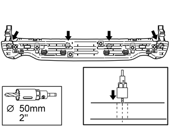
- Turn the bumper rail so that the studs point downwards
- Locate the four pre-drilled holes
- Drill out the holes through the entire bumper rail. Use a Ø50 mm (2”) diameter hole saw
- When the hole saw reaches the bottom, turn the bumper rail. Drill from the other side.
Примечание: Use a long central drill bit with the hole saw.
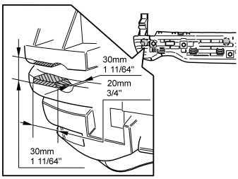
- Cut out a further 20 mm (3/4") towards the point where the connectors will be connected. This is to make room for the connectors for the sensors. The width must be 30 mm (1 11/64"). The depth must be 30 mm (1 11/64").
Примечание: Install the bumper rail. First check which holes are affected.
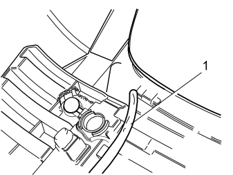
- Press the bumper rail into place in the foam and the bumper cover
- Route the cable (1) from the sensors as illustrated
- Ensure that all the mounting hooks have secured.
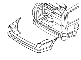
- Cut off the rubber bushing on the cable harness
- Lift the bumper into position
- Route the cable harness for the sensors through the existing hole in the rear crossmember, to the right in the gap by the rear crossmember. Continue into the cargo compartment through the oval hole above the hole for the aerial switch.
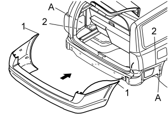
Примечание: Ensure that the loose mountings (A) for the sides of the bumper are in position on the right and left sides.
- Reinstall the bumper. Locate the ends of the bumper (1) in the rails (2). Push in
- Reinstall the four nuts. Tighten to 18 Nm (13 lbf ft).
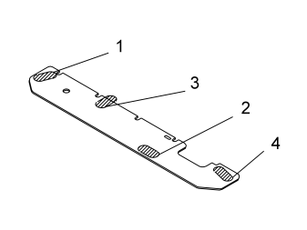
Applies to cars with lining mats with four perforations, according to point
-
Install the rubber tabs (from the kit) over the four installed nuts as follows:
-
Align the rubber tabs (1, 4) edge to edge with the lining mat. If necessary, cut away the area (1) around the nut so that the nut is accessible
- Compress the rubber tab (2) slightly to align in the cut out
- Align the rubber tab (3) so that the lower edge is positioned edge to edge with the lining mat. Cut off the section protruding over the lining mat. (Do not cut off an excessive amount)
- Make a cut (using a knife) in one rubber tab (4). This is so that the cable harness for the sensor can be inserted.
Applies to cars with lining mats with one perforation, according to point
- Install a new lining mat.
Applies to all cars
- Reinstall the antenna connector.
- Tighten the bumper cover using the screws at the rear of the wheel arch on the right and left-hand sides
- Secure the bumper cover using blind rivets at the lower rear edge of the wheel arch on the left and right hand sides
- Reinstall the four clips on the underside of the bumper in the centre.
Примечание: Leave the backing on the bumper. The backing will be needed later when painting the sensors and sensor holders.
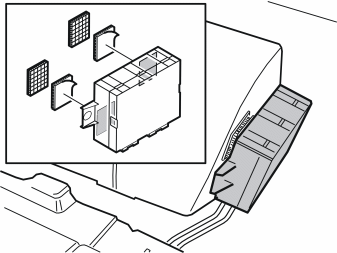
- Mark the surfaces for the location of the Velcro strips on the control module. Also mark the rear edge of the air vent in the rear right-hand wheel arch
- Install the Velcro strips
- Connect the wiring from the sensors and the 16-pin cable connector (from the kit) to the control module
- Install the control module.
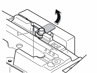
- Slacken off the screw (1) in the lock facing for the Accessory Electronic Module, behind the right wheel well, a few turns
- Pull the lock facing out to the right. Remove the lock facing.
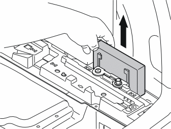
- Lift the Accessory Electronic Module from the bracket.
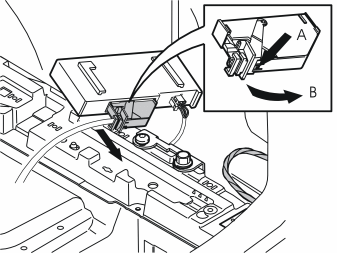
- Disconnect the large connector from the Accessory Electronic Module. First press in catch (A). Pull the black locking handle (B) in the direction of the arrow until a click is heard. Disconnect the connector
- Disconnect the connector from the Accessory Electronic Module.
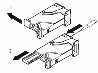
- Remove the black catch holding the black switch in place in the connector by pulling in the direction of the arrow
- Remove the black switch by inserting a pointed object in the hole on the other end. Press the switch out.
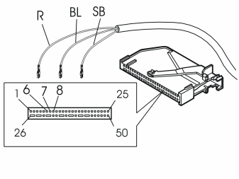
- Connect the small cable harness from the control module to the black connector for the Accessory Electronic Module as follows:
Примечание: The number markings can be found on the top and underneath the black switch. However, the markings are extremely small so be careful when installing the three cables.
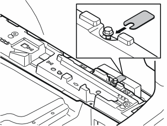
- Reinstall the black switch in the connector. Press the lock into place with the catch
- Press the connector into the Accessory Electronic module. Secure using the black locking handle
- Reinstall the Accessory Electronic Module. Secure any excess wiring
- Reinstall the lock facing above the Accessory Electronic Module. Tighten the screw. Tighten to 10 Nm (8 lbf.ft.).
- Clean the visible surfaces on the sensors and the sensor holders. Use cleaning pads (P/N 9192678). Allow to dry
- Apply a thin layer of primer (P/N 9192679) over the sensors and the sensor holders. Allow to dry for at least 10 minutes
- Paint the sensor holders and sensors according to separate instructions (P/N 8641279) in the kit.
Примечание: Use a Volvo recommended paint. Apply a maximum of two layers of paint.
Осторожно: Too many layers of paint may result in partial or complete malfunction. The sensors must be painted in order to function properly.
- Remove the backing from the bumper.
- Connect the battery negative terminal
- Reinstall the battery cover and holder
- Reinstall the right-hand side panel
- Reinstall the folding panel
- Reinstall the storage box
- Reinstall the rear floor hatch
- Check the function.
Обсуждение и оценка
0Пока нет комментариев. Будьте первым.