Примечание: During installation the underlay must be kept at a temperature of at least +15°C (60°F).
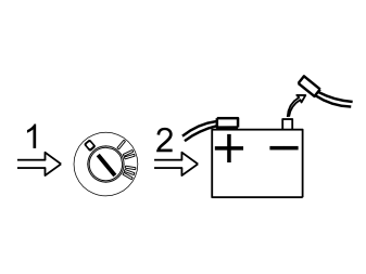
- Turn the ignition key to position 0
- Make a note of the radio code
- Disconnect the battery negative lead.
Примечание: Wait at least five minutes before disassembling the connectors or removing other electrical equipment.
- Clean the bumper. Use a mild soap solution.
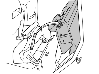
Applies to V70 and V70XC models
- Fold up the seat cushion and fold down the backrest on the left hand side of the rear seat
- Remove the side cushion.
Illustration A applies to C70 and S70 models
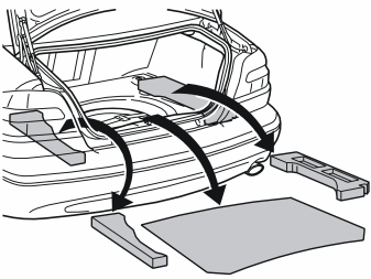
Illustration B applies to C70 and S70 models
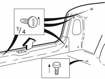
Illustration C applies to V70 and V70XC models
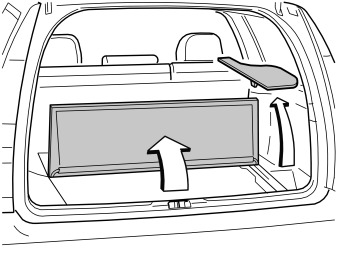
Illustration D applies to V70 and V70XC models
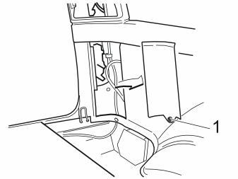
Applies to C70 and S70 models
- Remove the cargo compartment carpet.
Applies to C70 models
- Remove the holder for the warning triangle.
Applies to C70 and S70 models
- Remove the clips on the side panels and rear member. Turn the clips a quarter turn anti-clockwise
- Remove the panel on the rear member and push the side panels to one side.
Applies to V70 and V70XC models
- Remove the floor hatches and the panels for the left tail lamp
- Pull the carpet for the left hand wheel housing up and to one side.
Positioning the control module
Illustration A applies to the C70
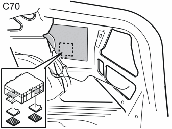
Illustration B applies to the S70
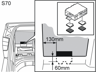
Illustration C applies to V70 and V70XC models
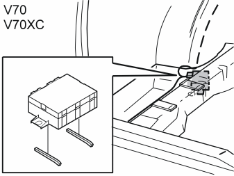
The location of the control module for:
- the C70 is on the right hand side of the bodywork.
- the S70 is on the left hand side of the bodywork.
- the V70 and V70XC is under the member in the left-hand wheel housing.
- Mark the surfaces for the position of the Velcro strip and the butyl tape on the control module and the side of the body
- Clean the marked surfaces using a wet cloth. Allow to dry
- Remove the protective film from the Velcro strip and butyl tape. Secure the strip on the marked surface on the control module
- Remove the protective film from the remaining Velcro strip and butyl tape. Secure on the marked surface on the body side and member
- Install the control module.
Connecting the buzzer
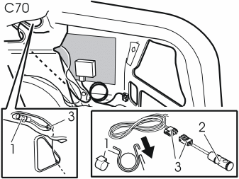
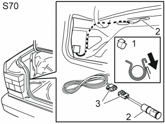
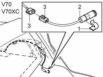
- Connect the 16 pin connector to the control module
- Route the control module cable harness as illustrated
- Install the clip (1) on the buzzer (2). Connect the 2-pin connector (3) as illustrated
- Install the buzzer as illustrated
- Clamp the cable harness. Place excess wiring beside the control module.
Connecting the wiring to the reversing lamp
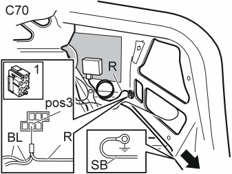
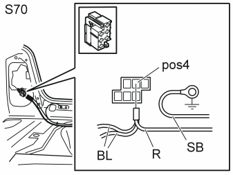
Applies to C70 and S70 models
- Take out the yellow 6-pin connector (1) behind the right hand tail lamp
- Open the connector. Remove the blue (BL) cable from terminal 3 for the C70 and terminal 4 for the S70
- Cut the cable terminal off the blue (BL) cable
- Twist the red (R) cable from the control module together with the blue (BL) cable. Insert the cables in terminal 3 for the C70 and terminal 4 for the S70
- Lock the connector. Install any blind connectors
- Install the cable terminal on the black (SB) cable. Connect the black (SB) cable to the existing ground point on the rear member
- Clamp the cable to the existing cable harness. Clamp any excess at the control module.
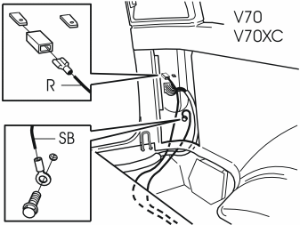
Applies to V70 and V70XC models
- Install cable terminals to the black (SB) and red (R) cable as illustrated
- Connect the red (R) cable to the left reversing lamp and the black (SB) cable to the existing ground point
- Clamp the cable to the existing cable harness. Clamp any excess at the control module.
Removing the bumper
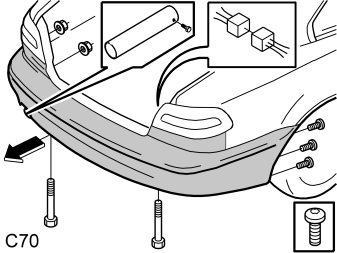
Applies to C70 models
- Remove the nuts under the tail lamp
- Disconnect the connector. Push the connector out through the hole in the bodywork
- Remove the tail pipe from the exhaust pipe
- Remove the screws from the bumper at the right and left-hand wheel arch edges
- Remove the screws from the mounting for the bumper
- Remove the bumper by pulling it straight backwards.
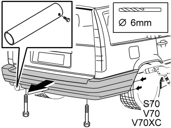
Applies to S70, V70 and V70XC models
- Remove the rear wheels
- Drill out the blind rivets for the bumper at the edges of the right and left-hand wheel arches. Use a 6 mm (15/64") diameter drill bit
- Remove the tail pipe from the exhaust pipe
- Remove the screws from the mounting for the bumper
- Remove the bumper by pulling it straight backwards.
Preparing the bumper

Applies to C70 models
- Install the backing paper. Evenly distribute the backing over the bumper.
Примечание: The backing paper is used to protect the paint.
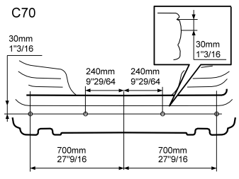
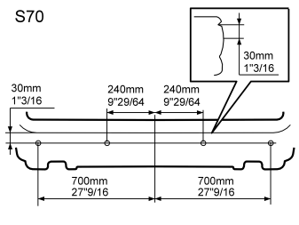
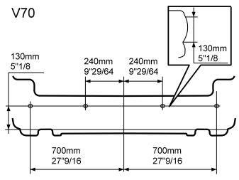
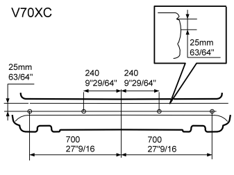
- Mark the centre of the bumper
- Mark the location for the sensor holders as illustrated.
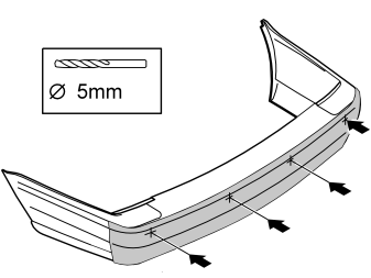
- Pre-drill 5 mm (3/16") diameter holes at the markings. Drill through the casing to the bumper. Drill approximately 40 mm (1 1/2") deep so that the drill bit reaches the foam.
Disassembling the bumper
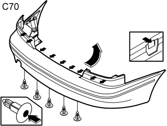
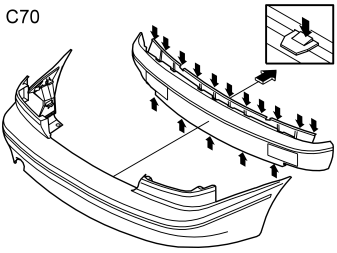
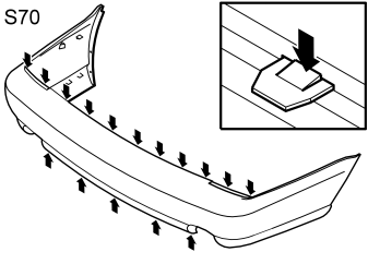
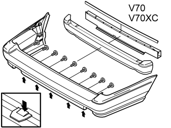
- Remove the expander rivets from the bumper by pressing in the locking pins
- Remove the clips / screws
- Remove the foam from the bumper casing.
Примечание: Do not remove the aerial from the foam (C70).
Drilling the bumper casing
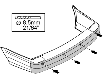
- Drill out the pre-drilled holes in the bumper casing using an 8.5 mm (21/64") diameter drill bit.
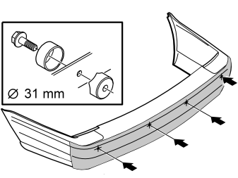
- Open the holes in the bumper casing. Use a 31 mm (1 7/32") diameter hole cutter, P/N: 9814069.
Cleaning and taping the mounting surfaces
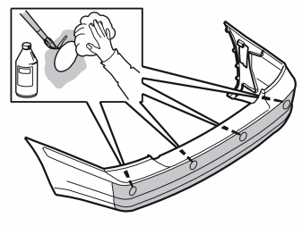
- Wash dirt and stones from the bumper casing. Use Cleaner H, P/N 1161436-9
- Clean around the drilled holes. Allow to dry. Use the wet cloth
- Apply primer (P/N 9192679) around the holes. Allow to dry.
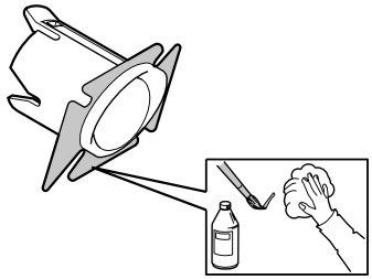
- Clean the mating surface on the sensor holders. Leave to dry. Use the wet cloth
- Apply the primer (P/N 9192679) to the cleaned surfaces of the holders. Allow to dry.
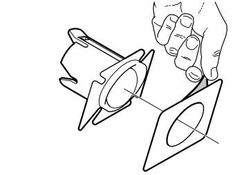
- Remove the protective film from one side of the tape
- Place the tape on the sensor holder
- Carry out the above procedure on the remaining 3 holders.
Installing the holders
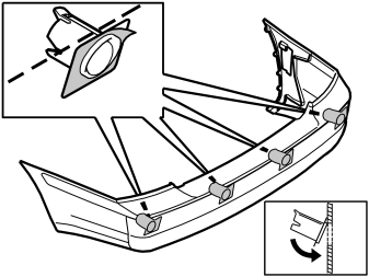
- Remove the protective film from the pieces of tape on the holders
- Install the holders for the sensors. The narrow side must be pointing upward. Install horizontally in line with the bumper casing, as illustrated.
Примечание: Ensure the tape is correctly positioned; the tape adheres immediately. The function may be impaired if the sensors are not positioned correctly.
Drilling for the sensors
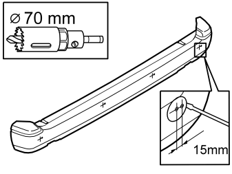
- Mark the holes for the sensors. Starting from the holes previously drilled in the foam, make new markings 15 mm (5/8") horizontally to the left
- Drill a diameter of 70 mm (2 3/4"), approximately 50 mm (2") deep. Use a hole saw
- Remove the drilled core from the foam.
Cutting the channels for the wiring
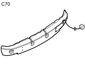
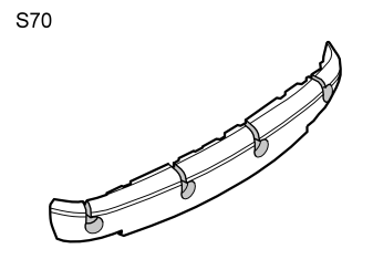
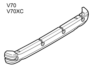
- Saw out grooves for the wiring which is routed to the sensors as illustrated. Use a hacksaw.
Installing the sensors
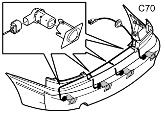
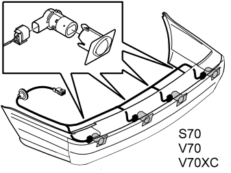
- Connect the cable harness connectors to the sensors.
Примечание: A click should be heard when connecting. The noise confirms that the catch has locked.
- Install the sensors in the holders.
Assembling the bumper
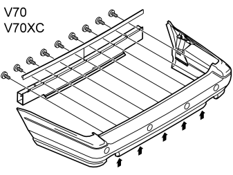
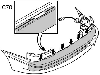
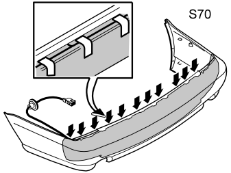
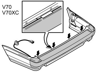
- Assemble the bumper components. Tape the cable harness as illustrated.
Drilling in the body
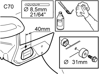
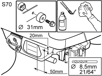
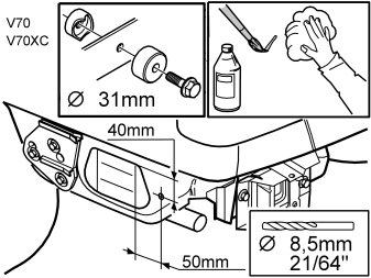
- Mark a hole for a lead-in for the cable harness as illustrated
- Drill an 8.5 mm (21/64") diameter hole at the marking
- Open the hole in the bumper casing. Use a 31 mm (1 7/32") diameter hole cutter, P/N: 9814069
- Rust-proof the edges of the hole.
- Clean the sensors and holders using a wet cloth. Allow to dry
- Apply a thin layer of primer (P/N 9192679) over the sensors and the sensor holders. Allow to dry for at least 10 minutes.
- Spray the sensor holders and the sensors. Use the same colour code as the car. Use Volvo recommended paint. Only paint the parts that will be visible after installation.
Примечание: Apply a maximum of two layers of paint. Too many layers of paint may have a negative impact on the function of the sensors. However, the sensors must be painted for optimal functionality.
- Remove the backing from the bumper when the paint has dried.
Routing wiring
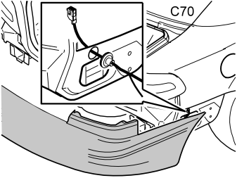
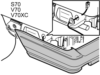
- Lift the bumper into position
- Route the cable harness for the sensors through the hole on the side. Install the rubber grommet
- Route any wiring for the aerial through the hole under the tail lamp.
Installing the bumper and other components
- Install and screw or rivet into place the bumper. Adjust the length of the cable harness at the rubber grommet
- Reinstall the rear wheels
- Reinstall the tail pipe
- Route the cable harness as illustrated. Connect it to the control module
- Connect the aerial wiring
- Clamp the wiring
- Reinstall any hatches and fold the cargo compartment carpet back into place
- Reinstall the panel for the tail lamp, side panels and any panels for the rear member
- Reinstall the holder for the warning triangle.
Applies to V70 and V70XC models
- Reinstall the side cushion
- Fold the backrest and seat back into place.
Switch for shutting off the reverse warning system. Used when reversing with a trailer for example
Illustration A
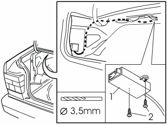
Applies to the S70
- Position the switch (1) under the parcel shelf near the buzzer. Mark out the hole
- Drill a 3.5 mm (9/64") diameter hole in the double panel. Install the switch using the screws (2) from the kit
- Route the cable, with the cable for the buzzer, to the reverse warning control module and on to the reversing lamp. Clamp the cable.
Illustration B
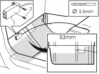
Applies to V70 and V70XC models
- Position the switch (1) in the upper edge of the insulation, maximum 53 mm (2") below the upper edge, below the rear side floor hatch in the cargo compartment
- Install the switch. Screw into place using the screws (2) from the kit
- Then route the cable to the reversing lamp. Clamp the cable.
Illustration C
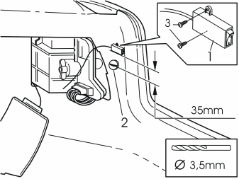
Applies to C70 models
- Position the switch (1) 35 mm (1 25/64") above the clip (2). The switch must be placed in line with the "edge" of the cargo compartment. Drill through the upholstery and the doubled plate. Use a 3.5 mm (9/64") diameter drill bit. Screw into place using the screws (3) from the kit
- Then route the cable to the reversing lamp. Clamp the cable.
Connecting the switch
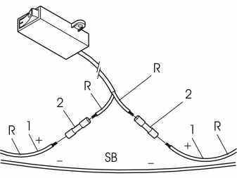
- Cut off the positive supply (1) to the control module
- Install the cable terminals (2) on the positive supply. Connect using the switch
- Clamp the excess cable.
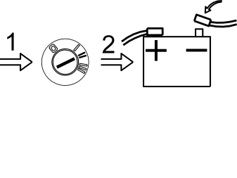
- Turn the ignition key to position (II)
- Reconnect the battery negative lead. Check the function
- Enter the anti-theft radio code.
Обсуждение и оценка
0Пока нет комментариев. Будьте первым.