Illustration A applies to the S40
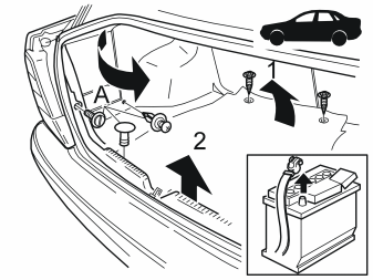
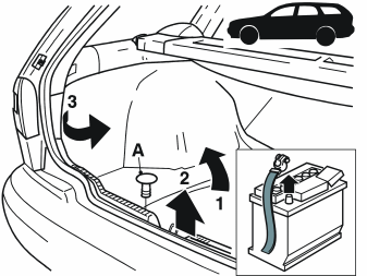
Illustration B applies to the V40
- Make a note of the anti-theft protection radio code if applicable
- Switch off the ignition
- Disconnect the battery negative lead
- Remove the 2 screws, the cargo compartment carpet and the rear wall panel
- Remove the clip (A) and turn the rear panels inwards on the left and right-hand sides. (For V40 with auxiliary loud speakers: See points 2, 3 and 4).
Applies to the S40
- Remove the entire left-hand panel in the cargo compartment.
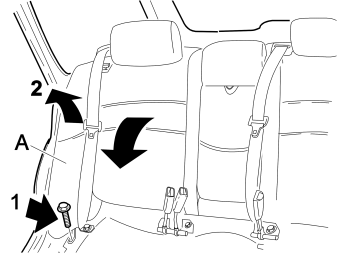
Applies to V40 models with extra loud speakers:
- Angle the rear seat forwards. Fold the right-hand backrest down
- Remove the fixed section (A) on the right-hand backrest.
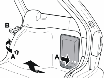
Applies to V40 models with extra loud speakers:
- Remove the parcel shelf
- Press together the clips. Pull off the cargo net from the reverse of the panel in the cargo compartment
- Remove the clip (A). Remove the screw (B)
- Where applicable: Remove the mountings for the protective net
- Remove the cargo compartment panel from underneath. Use a twisting movement.
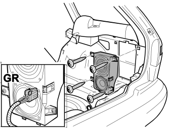
Applies to V40 models with extra loud speakers:
- Disconnect the grey (GR) connector (one or more)
- Remove the 4 screws
- Remove the extra loudspeaker.
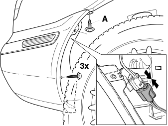
- Remove the 3 mounting screws / clips for the splashguards
- Remove the screw (A)
- Press in the catch. Disconnect the connector for the side marker lamp in the rear bumper
- The procedure is the same for both the left and right hand sides.
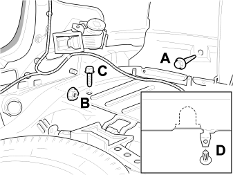
- Remove the nuts (A and B). Remove the screw (C)
- Carry out procedures A, B and C on both the right and left-hand sides
- Up to chassis number 600000: Remove the clip (D) from the underneath of the bumper
- Apply tape under the tail lamps to protect against damage to the paint work when removing the rear bumper
- Remove the rear bumper.
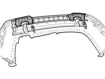
Applies only to V40 models
- Remove the 8 clips and the plastic supports on the right and left-hand sides.
Installing the sensors
Примечание: To prevent damage to the bumper cover when installing the sensors, the bumper cover must be placed on a foam underlay at least 3 cm thick.
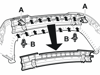
Applies to cars up to chassis number 600 000:
- Remove the clips (A) from on top
- Remove the clips (B) from underneath
- Press in the catches. Remove the bracket for the bumper. (Some force is required to remove the bracket).
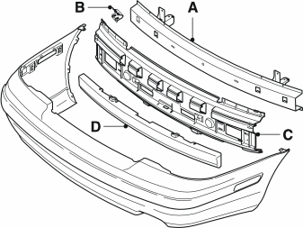
- Press in the catches. Remove the bracket (A)
- Start at one end. (Some force is required to remove the bracket.)
- Remove the two clips (B)
- Press in the catches. Remove the reinforcement (C). Start at one end.
Illustration A applies to cars with chassis numbers up to 600 000
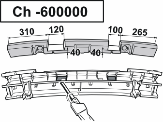
Illustration B applies to cars with chassis numbers from 600 000
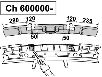
- Remove the shock absorbent rubber liner from the bracket
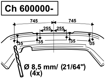
- Mark for holes in the bracket and liner as illustrated. Saw out holes using a pneumatic saw
- Reinstall the rubber liner in the bracket (use tape on the outside).
Illustration A applies to cars with chassis numbers up to 600 000
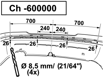
Illustration B applies to cars with chassis numbers from 600 000
- Find the centre of the bumper
- Apply masking tape to the surface surrounding the hole marks on the outside of the bumper
- Mark for four holes as illustrated
- Drill four 8.5 mm (21/64") diameter holes.
Illustration A applies to cars with chassis numbers up to 600 000
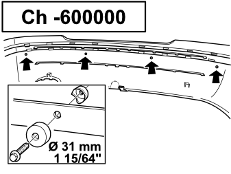
Illustration B applies to cars with chassis numbers from 600 000
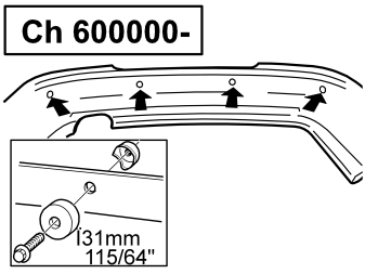
- Apply the special tool (Volvo P/N 9814069). Drill four 31 mm (1/4”) diameter holes. Drill from the outside. Do not damage the paintwork on the bumper.
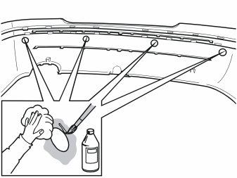
NOTE! The temperature of the bumper must be at least 15° C (60° F)
- Clean the inside of the bumper at the sensor holder. First use sandpaper and then cleaner H (Volvo P/N 1161436)
- Clean the inside using cleaning agent (P/N 9192678)
- Treat the inside of the bumper using Activator (P/N 8637076) at the sensor holder. (Leave at least 10 minutes to dry).
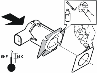
NOTE! The temperature of the sensors must be at least 15°C (60° F)
- Clean the holders for the sensors. Use cleaner H (Volvo P/N 1161436)
- (Use cleaning agent (P/N 9192678). Treat the mounting surfaces of the sensors using Activator (P/N 8637076). (Leave at least 10 minutes to dry.)
- Install the sensors in their holders
- Remove the masking tape and apply protective film to the sensor holders.
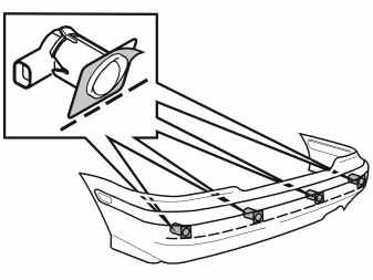
- Remove the masking tape. Install the sensor holders on the bumper. The thin section must be pointing upwards
- Ensure that the sensor holders are mounted straight.
Примечание: The function may be impaired if the sensors are not positioned correctly.
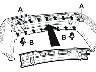
Applies to cars up to chassis number 600 000
-
Примечание: > Do not damage the paintwork on the bumper.
Press the bracket for the bumper into place. Ensure that all catches engage
- Install the clips (A) and (B).
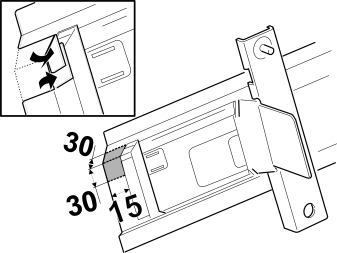
Applies to cars from chassis number 600 000
- Cut out three lines in the plate bracket. Bend in the bracket at these three points. (Use a pneumatic saw)
- Spray or paint rust solvent on the bracket.
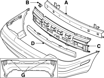
-
Примечание: > Do not damage the paintwork on the bumper.
Check that the bumper (D) is still in the reinforcement (C)
- Install the reinforcement (C) in the bumper cover. (Note the positions of the three guide lugs (G).) Start at the ends and work in towards the centre
- Install the clip (B)
- Install the bracket (A) in the reinforcement for the bumper. Start pressing in the ends and work in towards the centre
- Ensure that all the guide lugs are correctly aligned.
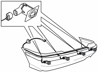
- Connect the sensor connectors
- Secure the cable harnesses using tape or tie straps.
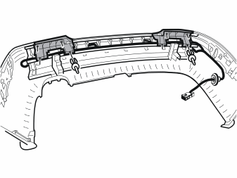
Applies only to V40 models
- Install the plastic supports and the 8 clips on the right and left-hand sides.
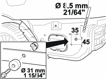
- Mark out and drill one 8.5 mm (21/64”) diameter hole
- Apply the special tool (Volvo P/N 9814069). Drill one 31 mm diameter hole
- Spray the inside of the holes using rust solvent.
- Clean the sensors and holders using cleaning agent (P/N 9192678-2)
- Apply a thin layer of primer (P/N 8637076-4) to the sensors and holders.
Примечание: The primer must dry for at least 10 minutes before it can be painted.
- Spray the sensor holders and the sensors. Use the same colour code as the car. Use Volvo recommended paint. Only paint the parts that will be visible after installation.
Примечание: Apply a maximum of two layers of paint. Too many layers of paint may have a negative impact on the function of the sensors. However, the sensors must be painted for optimal functionality.
- Remove the protective film from the bumper when the paint has dried.
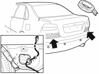
- Check that the tape under the tail lamps is intact
- Route the cable harness for the sensors to the rear wing liner. Install the rubber grommet. Ensure that the rubber grommet forms a seal
- Reinstall the bumper.
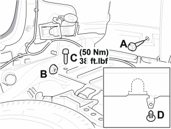
- Install the screw (C) and nuts (A and B). Hand tighten
- Tighten screw (C). Tighten to 50 Nm (37 lbf. ft). Tighten the nuts (A and B). Tighten to 5 Nm (4 lbf. ft). Tighten on both the left and right hand sides.
Applies to cars up to chassis number 600 000
- Install the clip (D) on the underneath of the bumper.
- Connect the connector for the side marker lamp
- Install the screw (A)
- Reinstall the 3 mounting screws / clips for the splashguards
- The procedure is the same for both the left and right hand sides.
Illustration A applies to the S40
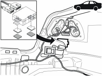
Illustration B applies to the V40
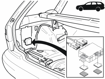
- Connect the 12 and 16-pin connectors to the control module
- Remove the backing and apply the double-sided adhesive tape to the control module
- Remove the backing tape and install the control module as illustrated
- Secure the control module using a little force.
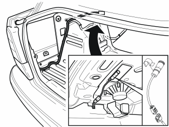
Applies only to S40 models
- Route the 2-pin connector along the existing cable harness to the left rear loudspeaker
- Secure one clip on the buzzer. Secure the clip on the edge of the left-hand loudspeaker panel
- Connect the connector.
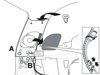
Applies only to V40 models
- Remove the loudspeaker grille and the screw (A)
- Remove the lighting for the cargo compartment. Remove the wiring
- Remove the screw (B). Carefully remove the panel
- Route the 2-pin connector along the existing cable harness to the left rear loudspeaker
- Connect the connector to the buzzer. Secure the buzzer to the existing cable harness using a tie-strap.
Shut-off switch for the reverse warning sensor (Used when reversing with a trailer for example.):
Illustration A applies to the S40
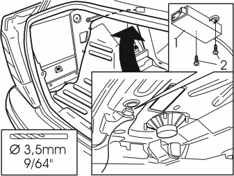
- Position the switch (1) beside the buzzer under the parcel shelf. Mark for drilling.
Illustration B applies to the V40
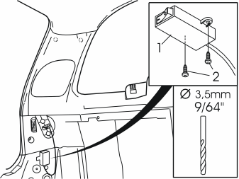
- Position the switch (1) in the protective cover for the left tail lamp. Mark for drilling.
Applies to both
- Drill two 3.5 mm (9/64") diameter holes in the doubled plate
- Install the switch with two screws from the kit
- Route the cable back towards the control module for the reverse warning system.
Reversing lamp:
Illustration A applies to the S40
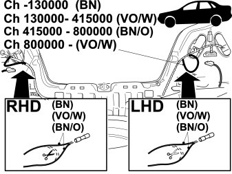
Illustration B applies to the V40
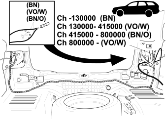
- Locate the ring cable for the reversing lamps;
- Cut off the cable and install the cable terminal.
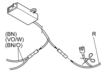
- Cut off the cable terminal from the red (R) cable
- Install the cable terminals from the switch. See the illustration.
Ground:
Illustration A applies to the S40
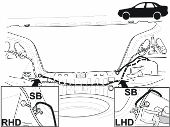
Illustration B applies to the V40
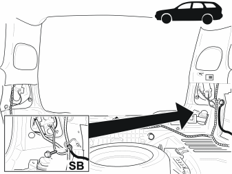
- Connect the cable terminal to the black (SB) cable
- Connect the black (SB) cable to ground on the tail lamp
- Secure all cables using tie straps.
- Remove the tape and clean the rear bumper
- Turn the ignition to position II
- Ensure that no one is inside the car
- Connect the battery negative lead
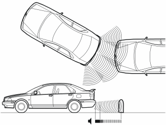
- Check that the reverse warning sensors are working (activates only when there is an object in the way behind the vehicle when reversing)
- Check the sound signal from the buzzer. The sound signal can be adjusted by turning the outer cover on the buzzer
- Where applicable: re-enter the radio code
- Set the car clock to the correct time
- Reinstall the remaining components.
Обсуждение и оценка
0Пока нет комментариев. Будьте первым.