Примечание: During installation the underlay must be kept at a temperature of at least +15°C (60°F).
Preparations
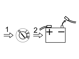
- Turn the ignition key to position 0
- Note the anti-theft radio code (if applicable)
- Disconnect the battery negative lead.
Примечание: Wait at least five minutes before disconnecting the connectors or removing other electrical equipment.
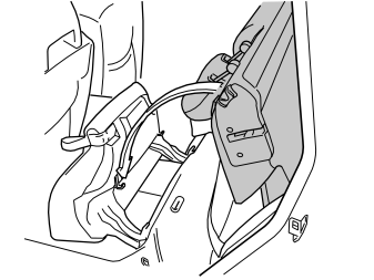
- Fold up the seat cushion and fold down the backrest on the left hand side of the rear seat
- Remove the side cushion.
Illustration 3A applies to C70 and S70
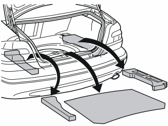
- Remove the cargo compartment carpet
- Applies to the C70:Remove the holder for the warning triangle.
Illustration 3B applies to C70 and S70
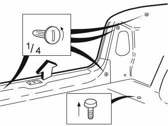
- Remove the clips on the side panels and rear member. Turn the clips a quarter turn anti-clockwise
- Remove the panel on the rear member and push the side panels to one side.
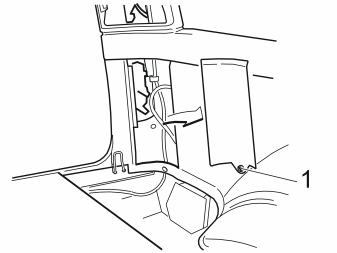
Illustration 3C and 3D apply to the V70 and V70 XC
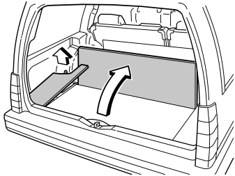
- Remove the floor hatches and the panels for the left tail lamp
- Pull the mat for the left hand wheel housing up and to one side.
Installing the control module
Illustration 4A applies to the C70
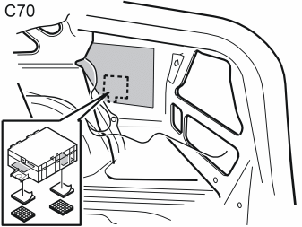
Illustration 4B applies to the S70
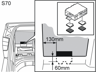
Illustration 4C applies to the V70 and the V70 XC
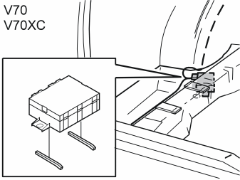
- Mark the surfaces for the position of the Velcro strip and the butyl tape on the control module and the side of the body
- Clean the marked surfaces using a wet cloth. Allow to dry
- Remove the protective film from the Velcro strip and butyl tape. Secure the strip on the marked surface on the control module
- Remove the protective film from the remaining Velcro strip and butyl tape. Secure on the marked surface on the body side and member
- Install the control module.
The location of the control module for:
- the C70 is on the right hand side of the bodywork
- the S70 is on the left hand side of the bodywork
- the V70 and V70XC is under the member in the left-hand wheel housing.
Installing buzzer C70 Cabriolet
Примечание: Points 5-13 apply to the C70 Cabriolet.
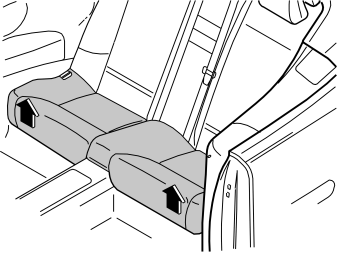
- Remove the seat cushion from the rear seat by pulling it straight upward at the front edge.
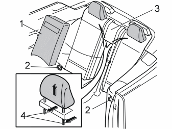
Remove:
- the centre section (1)
- the nuts (2)
- the head restraint by inserting the hand behind the backrest cushion (3) and pressing the head restraint hooks (4) forward.
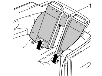
- Remove the backrest cushion (1) by pulling it outwards and lifting upwards.
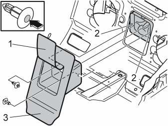
- Open the cover (1) and remove the clips (2) by pressing the centre of the clip.
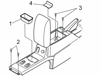
Remove:
- the compartment (1) in the centre console. Pry it loose using a weatherstrip tool
- the screws (2)
- the screws (3) under the cover.
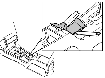
- Remove the handbrake lever and boot. Carefully pry the panel free along longest edge using a weatherstrip tool. Pull the panel free and thread it over the handbrake lever.
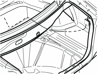
- Connect the 16- pin connector to the control module
- Route the cable harness for the buzzer from the control module along the right-hand rear wheel well, inside the front panel in the cargo compartment. Continue along the hoses and wiring to the fuel tank unit
- Remove the seal for the hole in the bodywork on the left side of the right hand loudspeaker cut out
- Pull the cable harness out from the hole in the bodywork beside the cover for the fuel tank unit and out through the exposed hole
- Take the rubber bushing from the kit. Thread the rubber bushing onto the cable harness
- Press the rubber bushing for the cable harness into place in the hole.
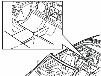
- Route the cable harness under the insulation on the right hand side of the rear seat, under the mat beside the centre console and along the centre console forwards to the left hand side of the handbrake lever. Position the cable harness in the centre console in such a way that it is not damaged by the handbrake lever and cables, or is trapped when the centre console is tightened.
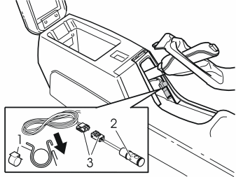
- Install the clip (1) on the buzzer (2). Connect the 2-pin connector (3). Install the buzzer as illustrated. Any excess wiring can be hidden in the centre console. Do not damage the wiring.
- Reinstall the handbrake lever panel
- Tighten the centre console.
Reinstall:
- the compartment and bottom of the centre console locker
- the panel between the loudspeaker cut-outs in the rear seat
-
the backrest with centre section and headrest.
-
Reinstall the seat cushion.
Installing the buzzer C70 Coupe, S70, V70 and V70 XC
Illustration 14A applies to the C70 Coupe
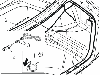
Illustration 14B applies to the S70
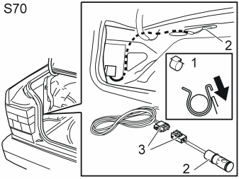
Illustration 14C applies to the V70 and the V70 XC
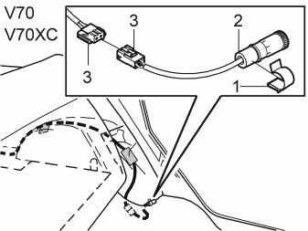
- Connect the 16 pin connector to the control module
- Route the control module cable harness as illustrated
- Install the clip (1) on the buzzer (2). Connect the 2-pin connector (3) as illustrated
- Install the buzzer as illustrated
- Clamp the cable harness. Place excess wiring beside the control module.
Reversing lamp connection
Illustration 15A applies to the C70
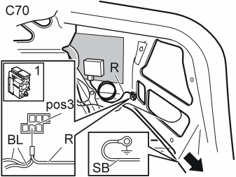
Illustration 15B applies to the S70
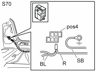
- Take out the yellow 6-pin connector (1) behind the right hand tail lamp
- Open the connector. Remove the blue (BL) cable from terminal 3 for the C70 and terminal 4 for the S70
- Cut the cable terminal off the blue (BL) cable
- Twist the red (R) cable from the control module together with the blue (BL) cable. Insert the cables in terminal 3 for the C70 and position 4 for the S70
- Lock the connector. Install any blind connectors
- Install the cable terminal on the black (SB) cable. Connect the black (SB) cable to the existing ground point on the rear member
- Clamp the cable to the existing cable harness. Clamp any excess at the control module.
Illustration 15C applies to the V70 and the V70 XC
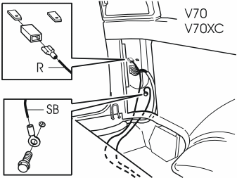
- Install cable terminals to the black (SB) and red (R) cable as illustrated
- Connect the red (R) cable to the left reversing lamp and the black (SB) cable to the existing ground point
- Clamp the cable to the existing cable harness. Clamp any excess at the control module.
Preparations to the bumper
Illustration 16A applies to the C70
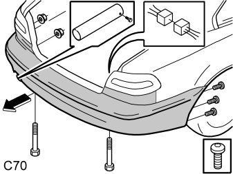
- Remove the nuts under the tail lamp
- Disconnect the connector. Push the connector out through the hole in the bodywork.
Remove:
- the end pipe from the exhaust pipe
- the screws for the bumper at the right and left-hand wheel arch edges
- the screws from the bumper mounting
- the bumper by pulling it straight backwards.
Illustration 16B applies to the S70, V70 and the V70 XC
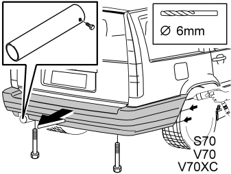
- Remove the rear wheels
- Drill out the blind rivets for the bumper at the edges of the right and left-hand wheel arches. Use a Ø 6 mm (15/64") drill bit.
Remove:
- the end pipe from the exhaust pipe
- the screws from the bumper mounting
- the bumper by pulling it straight backwards.

- Install the backing paper. Evenly distribute the backing over the bumper.
Примечание: The backing paper is used to protect the paint.
Illustration 18A applies to the C70
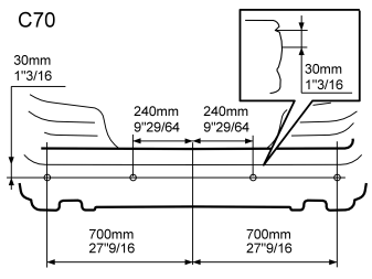
Illustration 18B applies to the S70
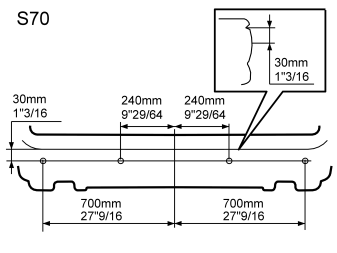
Illustration 18C applies to the V70
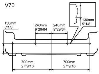
Illustration 18D applies to the V70 XC
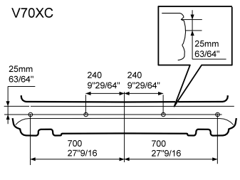
- Mark the centre of the bumper
- Mark the location for the sensor holders as illustrated.
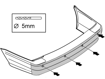
- Pre-drill 5 mm (3/16") diameter holes at the markings. Drill through the casing to the bumper. Drill approximately 40 mm (1 1/2") deep so that the drill bit reaches the foam.
Illustration 20A applies to the C70
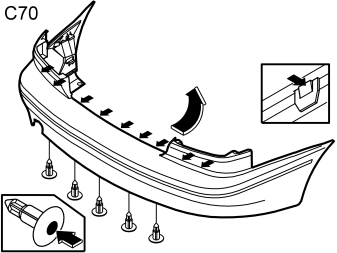
Illustration 20B applies to the C70
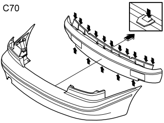
Illustration 20C applies to the S70
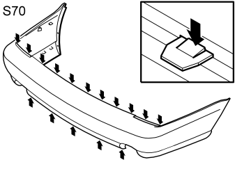
Illustration 20D applies to the V70 and the V70 XC
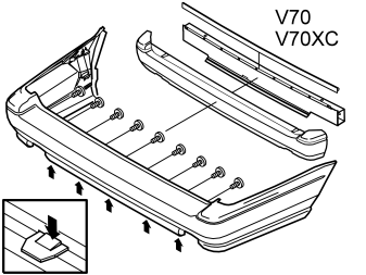
Remove:
- the expander rivets from the bumper by pressing in the locking pins
- the clips and screws
- the foam from the bumper casing.
Примечание: Do not remove the aerial from the bumper casing.
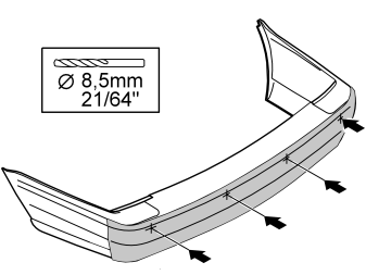
- Drill out the pre-drilled holes in the bumper casing using an 8.5 mm (21/64") diameter drill bit.
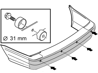
- Open the hole in the bumper casing. Use a 31 mm (1 7/32”), diameter hole cutter (P/N 9814069).
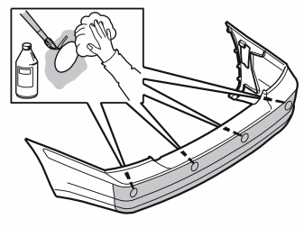
- Wash dirt and stones from the bumper casing. Use Cleaner H, P/N 1161436-9
- Clean around the drilled holes using the wet cloth. Allow to dry
- Apply primer (P/N 9192679) around the holes. Allow to dry.
Installing the sensor holders
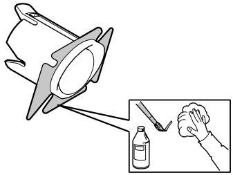
- Clean the mounting surfaces on the sensor holders using the wet cloth. Allow to dry
- Apply primer (P/N 9192679) on the cleaned surfaces of the sensor holders. Allow to dry.
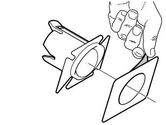
- Remove the protective film from one side of the tape
- Secure the tape on the sensor holder
- Carry out the above procedure on the remaining three sensor holders.
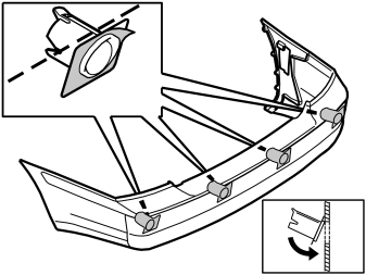
- Remove the protective film from the pieces of tape on the sensor holders
- Install the holders for the sensors. The narrow side must be pointing upward. Install horizontally in line with the bumper casing, as illustrated.
Примечание: The tape adheres immediately.
Осторожно: Incorrect positioning of the sensors may result in partial or complete malfunction.
Installing the sensors
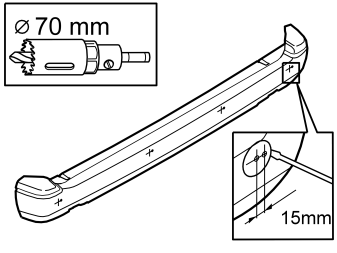
- Mark the holes for the sensors. Starting from the holes previously drilled in the foam, make new markings 15 mm (5/8”) horizontally to the left
- Drill Ø 70 mm (2 3/4"), approximately 50 mm (2") deep. Use a hole saw
- Remove the drilled core from the foam.
Illustration 28A applies to the C70
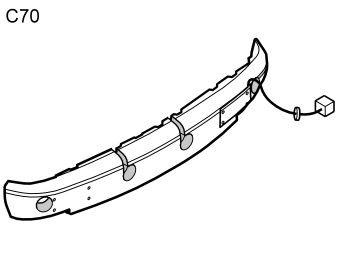
Illustration 28B applies to the S70
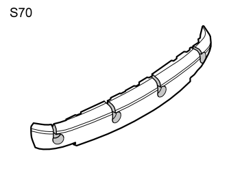
Illustration 28C applies to the V70 and the V70 XC
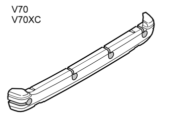
- Saw out grooves for the wiring which is routed to the sensors as illustrated. Use a hacksaw.
Illustration 29A applies to the C70
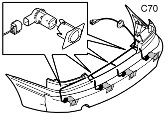
Illustration 29B applies to the S70, V70 and the V70 XC
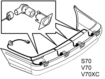
- Connect the cable harness connectors to the sensors.
Примечание: A click should be heard when connecting. The noise confirms that the catch has locked.
- Install the sensors in the holders.
Illustration 30A applies to the V70 and the V70 XC
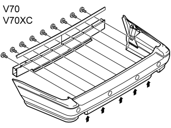
Illustration 30B applies to the C70
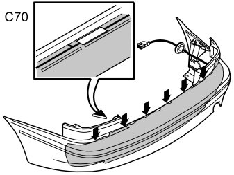
Illustration 30C applies to the S70
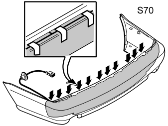
Illustration 30D applies to the V70 and the V70 XC
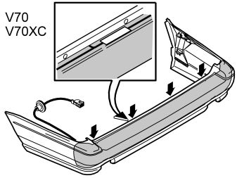
- Assemble the bumper components. Tape the cable harness as illustrated.
Painting the sensor holders and sensors
- Clean the sensors and the sensor holders using the wet cloth. Allow to dry
- Apply a thin layer of primer (P/N 9192679) to the sensors and the sensor holders.
Примечание: Only paint the components that are visible after installation.
Illustration 32A applies to the C70
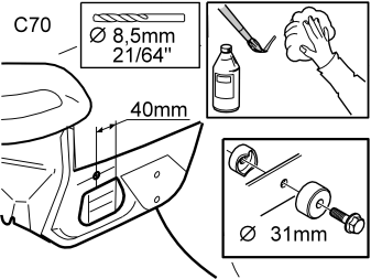
Illustration 32B applies to the S70
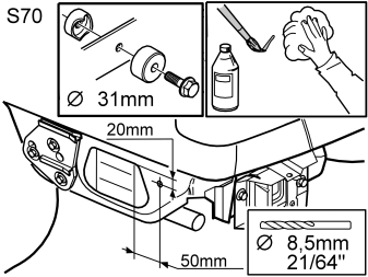
Illustration 32C applies to the V70 and the V70 XC
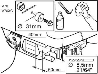
- Mark a hole for a lead-in for the cable harness as illustrated
- Drill a 8.5 mm (21/64") diameter hole at the marking
- Open the hole in the body. Use a 31 mm (1 7/32"), diameter hole cutter (P/N 9814069)
- Rust-proof the edges of the hole.
Примечание: Ensure that the primer has dried (10 minutes) before painting.
- Spray the sensor holders and the sensors the same colour as the car. Use a Volvo recommended paint. Apply a maximum of two layers of paint.
Осторожно: Too many layers of paint may result in partial or complete malfunction.
- Remove the backing from the bumper when the paint has dried.
Illustration 34A applies to the C70
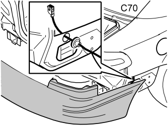
Illustration 34B applies to the S70, V70 and the V70 XC
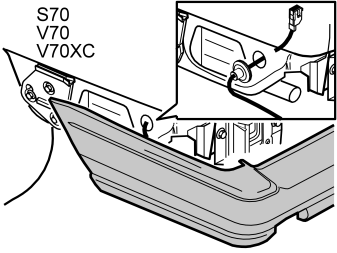
- Lift the bumper into position
- Route the cable harness for the sensors through the hole on the side. Install the rubber grommet
- Route any wiring for the aerial through the hole under the tail lamp.
- Install the bumper. Screw or rivet the bumper into place. Adjust the length of the cable harness at the rubber grommet
- Reinstall the rear wheels
- Reinstall the end pipe
- Route the cable harness as illustrated. Connect it to the control module
- Connect the aerial cable
- Clamp the wiring
- Reinstall any hatches and fold the cargo compartment carpet back into place
- Reinstall the panel for the tail lamp, side panels and any panels for the rear member
- Reinstall the holder for the warning triangle.
Applies to the V70, V70 XC
- Reinstall the side cushion
- Fold the backrest and seat back into place.
Installing the switch
Illustration 36A applies to the C70
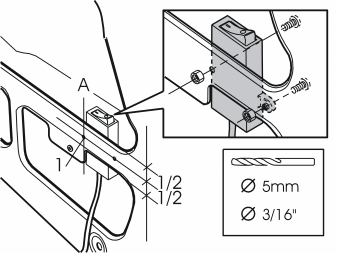
- First drill a hole (1) for the switch at line A, at half the distance of the width of the panel, under the right rear lamp. Use a Ø5 mm (3/16") drill bit
- Insert the switch straight into the front side of the panel under the tail lamp. Tighten using a screw and nut
- Mark out for drilling the other hole in the panel
- Remove the switch and drill the hole out
- Treat the edges of the holes using a rust-proofing agent
- Install the switch on the rear side of the panel under the tail lamp using nuts and screws from the kit
- Route the cable to the tail lamp. Clamp the cable in position.
Illustration 36B applies to the S70
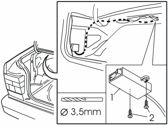
- Position the switch (1) under the parcel shelf near the buzzer. Mark out the hole
- Drill a Ø 3.5 mm (9/64") hole in the double panel. Install the switch using the screws (2) from the kit
- Route the cable, with the cable for the buzzer, to the reverse warning control module and on to the tail lamp. Clamp the cable.
Illustration 36C applies to the V70 and the V70 XC
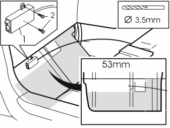
- Position the switch (1) in the upper edge of the insulation, maximum 53 mm (2") below the upper edge, below the rear side floor hatch in the cargo compartment
- Install the switch. Screw into place using the screws (2) from the kit
- Then route the cable to the tail lamp. Clamp the cable.
The switch to switch off the reverse warning system is used when reversing with a trailer.
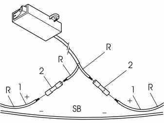
- Clip the positive supply (1) to the control module
- Install the cable terminals (2) on the positive supply. Connect using the switch
- Clamp the excess cable.
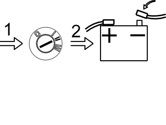
- Turn the ignition key to position II
- Reconnect the battery negative lead. Check the function
- Enter the anti-theft radio code.