Примечание: During installation the underlay must be kept at a temperature of at least +15°C (60°F).
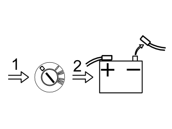
- Turn the ignition key to position 0
- Remove the ignition key from the ignition lock. (Does not apply to cars with automatic gearboxes.)
Примечание: Wait at least one minute before disconnecting the connectors or removing other electrical equipment.
- Clean the bumper. Use a mild soap solution.
Preparatory work in the cargo compartment that applies to the V50. (For preparatory work in the S40 (04-), go to point 9)
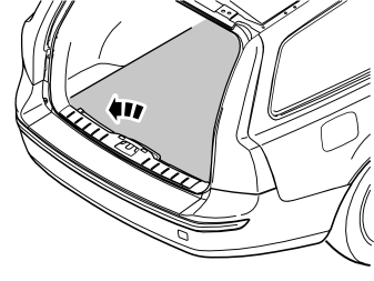
- Remove the cargo compartment carpet.
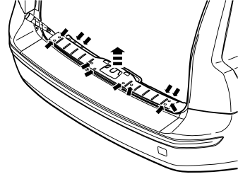
- Pry off the four external clips at the front edge/bottom edge of the sill trim panel on the tailgate
- Pry up one of the corners of the sill trim panel so that the two clips at that end release. Use a weatherstrip tool
- Pull up the sill trim panel so the remaining six clips release. Remove the panel
- Detach the rubber strip where it covers the right-hand side panel in the tailgate opening.
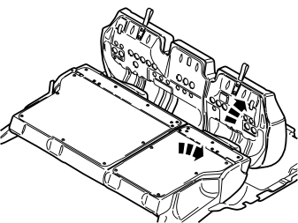
- Fold the seat cushion and backrest on the right-hand side of the rear seat forward.
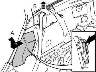
- Grasp the upper edge of the right-hand side cushion. Pull the side cushion forward so that the clip on the reverse releases
- Slide the side cushion upwards
- Remove the screw at the rear edge of the panel at the front/top of the right-hand side panel (B)
- Pull the panel upwards: So that the four clips on the inside release.
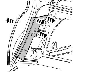
- Pull off the rubber strip at the rear of the opening for the right-hand rear door
- Carefully pry off the lower panel on the C-post on the right-hand side. Pry the top edge using a weatherstrip tool. Pull the C-post panel so that the two upper clips release
- Then continue down until the last two clips release. Remove the panel on the C-post.
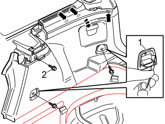
- Fold out the load securing eyelets on the right-hand side panel. Insert a scriber with an angled tip into the holes in the top of the covers (1). Turn the scriber so that the tip engages the reverse of the covers. Pull the covers off
- Remove the screws in the load securing eyelets
- Remove the screw (2) at the front/top edge of the side panel
- Pull off the side panel at the top so that the two clips at the rear/bottom of the side window and the clip at the bottom of the D-post release. If the car has a 12V socket in the side panel, disconnect the connector from this socket
- Lift out the side panel.
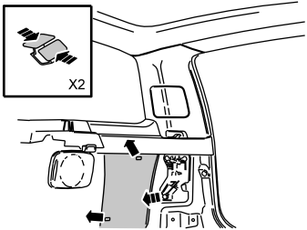
- Remove the insulation panel on the right-hand side. The insulation panel is secured by two clips behind the rear wheel arch.
Preparatory work in the cargo compartment that applies to the S40 (04-)
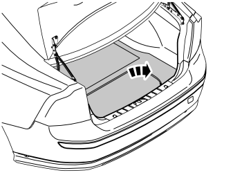
- Remove the cargo compartment carpet.
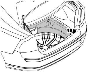
- Remove the upper floor supports from the car (if applicable).
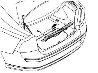
- Unscrew the two external clips at the front edge/bottom edge of the sill trim panel on the tailgate
- Pry up one of the corners of the sill trim panel so that the two clips at that end release. Use a weatherstrip tool
- Pull up the sill trim panel at the other end so that the remaining two clips release. Remove the sill trim panel
- Detach the rubber strip where it covers the right-hand side panel in the tailgate opening.
Illustration A
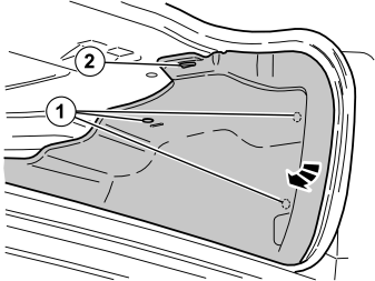
- Remove the four clips that hold the right-hand side panel in the bodywork
- Remove the four clips that hold the right-hand side panel in the bodywork
- Unhook the side panel from the rear load securing eyelet. Lift out the side panel.
Illustration B
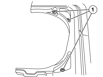
- Unscrew the three plastic clips (1) holding the lower floor support
- Lift out the floor support.
Preparatory work that applies to both the S40 (04-) and the V50
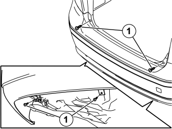
- Raise the car
- Remove the four screws (1) for the bumper. The screws are underneath the bumper and on the sides at the bottom of the tailgate opening.
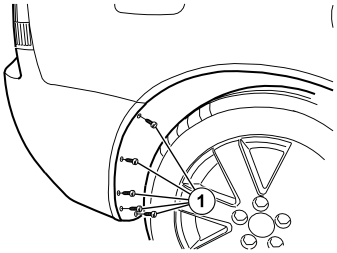
- Remove the five screws (1) holding the bumper cover at the rear edge of the wing liner in the rear wheel arch
- Repeat the procedure on the other side of the car.
Illustration A

- Remove the end of the bumper cover. Grasp the bumper cover inside the wing liner. Pull carefully until the six catches at the top edge release
- Repeat on the other side.
Illustration B
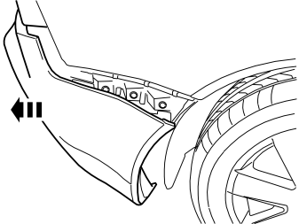
- Remove the bumper cover by pulling it straight backwards.
Примечание: It is recommended that two people lift down the outer bumper cover.
- Place the bumper cover on an underlay which will not damage the paint.
Installing sensors
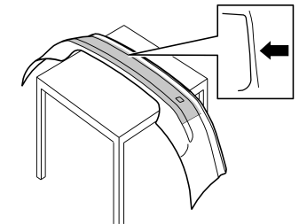
- Install the backing paper on the bumper.
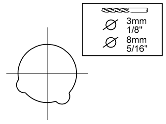
- Pre-drill holes in the centre of the drill markings on the inside of the bumper cover. Pre-drill using a 3 mm (1/8”) diameter drill bit
- Drill out the holes at the drill markings on the inside of bumper cover. Drill from the inside. Use a 8 mm (5/16”) diameter drill bit. Drill at the pre-drilled holes from the inside of the bumper cover.
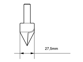
- Turn the bumper cover and drill out the holes from the outside. Use a 27.5 mm diameter special drill bit. P/N 9997114.
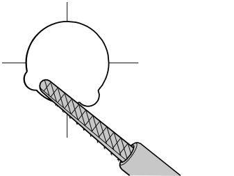
- File out the small cut-outs. Do not damage the paintwork.
Примечание: Only file exactly what is required. Otherwise the edges of the holes will be visible outside the edges of the sensor holders.
- Smooth the edges after using the hole tool if necessary
- Repeat this procedure at all four drill markings
- Wash out the bumper cover. Use a mild soap solution.
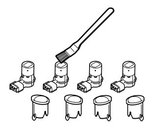
- Take the reverse warning sensors from the kit
- Clean the sensors and holders using a wet cloth. Allow to dry
- Apply a thin layer of primer (P/N 9192679) over the sensors. NOTE! Only paint the parts that are visible after installation
- Position the sensors so that you can paint the sensor surface and so that they do not tip over.
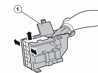
- Cut away the rubber grommet located on the sensor cable. Discard the rubber grommet. The rubber grommet will not be used again
- Remove the black plastic shell on the connector that connects the sensor cable to the PAS box
- Pry the plastic shell apart in the direction indicated by the arrows. Fold up the lid (1)
- Pry the shell apart until the hooks release the white inner connector. Pull up the connector.
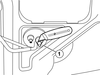
- Cut away one of the free rubber nipples on the rubber grommet (1) on the right-hand side of the car while waiting for the primer to dry. Only cut away the top of the rubber nipple. The hole must seal properly around the sensor cable, which is to enter the cargo compartment.
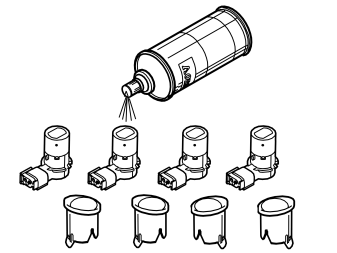
-
Примечание: > Allow to dry for at least 10 minutes before painting
Spray the sensor holders and the sensors. Use the same colour code as the car. Use Volvo recommended paint. Only paint the parts that will be visible after installation.
Осторожно: Apply a maximum of two layers of paint. Too many layers of paint may have a negative impact on the function of the sensors. However, the sensors must be painted for optimal functionality.
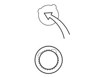
- Align the sensor holders in the filed cut-outs on the outside of the bumper cover. Press the sensor holders in so that the hooks engage in the bumper cover.
Примечание: All the holders have a unique shape and only fit in one of the holes. Ensure you have found the correct hole before installing the holder and pressing it into place.
- Ensure that the sensors are aligned with the hooks for the sensor holders. Press the sensors into place until a click confirms that they are properly located
- Take the cable harness for the sensors from the kit. Connect the sensors to the cable harness connectors.
Примечание: A click should be heard when connecting. The noise confirms that the catch has locked.
Preparations and routing the cable harness for the sensors
- Using a brush, apply primer to the inside of the bumper cover where the cable harness is to be secured (primer P/N 9192679)
- Secure the cable harness to the inside of the bumper cover using butyl tape from the kit.
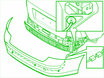
- Use expander pliers to widen the hole in the rubber grommet. Lubricate the rubber grommet using a substance that does not damage the rubber in order to facilitate cable routing
- Lift the bumper cover into position
- Route the cable harness for the sensors through the hole you have made in the rubber grommet.
Installing and connecting the PAS box
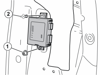
- Install the control box on the right-hand side of the cargo compartment beside the tail lamp. See illustration.
Applies to the V50:
- Screw the control box into place on the existing screws. Use the plastic nuts (1) from the kit.
Applies to the S40 (04-):
- Apply small pieces of butyl tape by the holes where the control box is to be installed. This will prevent rattling
- Secure the control box in the existing holes. Use the clips (2) from the kit.
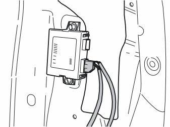
- Take the cable harnesses from the kit
- Connect the connectors to their corresponding sockets in the control box
- Connect the cable harness for the buzzer and the power connection
- Route the cable harness that previously entered the car through the rubber grommet. Route it to the reverse sensors
- Reinstall the black plastic shell on the sensor cable connector
- Connect the cable harness for the reverse sensors to the control box.
Примечание: Ensure that all the connectors click into place and are properly secured.
Cable routing in the V50 (For cable routing in the S40 (04-) go to point 33)
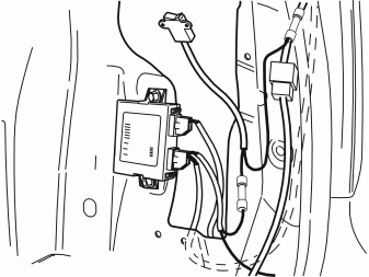
- Route the switch and electrical connection cables along the existing cable harness up to the right-hand tail lamp.
Illustration A
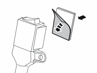
- Take the Velcro strip and the switch from the kit
- Remove the masking tape from the soft Velcro strip. Install the soft Velcro strip on the reverse of the switch. Press it into place
- Take the hard Velcro strip. Press the Velcro strips together on the switch.
Illustration B
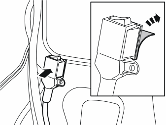
- Clean the panel surface directly below the right-hand tail lamp (viewed from behind). Use a mixture of 30% windscreen washer fluid and 70% water
- Wipe clean and dry
- Remove the masking tape from the hard Velcro strip. Press the switch with the Velcro strips onto the panel. See illustration.
Подсказка: When driving with a trailer, the reverse warning system should be switched off. This is done by pressing the switch to position 0.
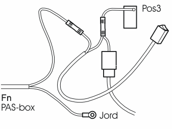
- Cut off the cable which goes to position 3 in the lower grey connector for the tail lamp
- Strip the end of the cable from the PAS box
- Adjust the length of the cable for the switch. Strip the cable ends
- Join the cable from the PAS box to one of the cables from the switch. Use a bonded crimping sleeve from the kit
- Join the other cable from the switch to the cut cables on the tail lamp. Use a bonded crimping sleeve
- Press the bonded crimping sleeves together. Heat the crimping sleeves until they seal tightly around the cables
- Strip the black cable from the PAS box. Press a ground terminal sleeve onto the cable
- Ground the cable in the existing ground terminal below the tail lamp.
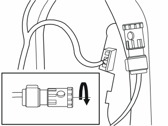
- Connect the buzzer to the cable connector
- Route the cable together with the buzzer up along the right-hand side of the cargo compartment to the D-post
- Pry out the bottom edge of the hatch in the centre of the D-post. Then pull the hatch straight down. Remove the hatch
- Route the buzzer up inside the panel to the edge of the plate in the hole
- Secure the buzzer around the edge of the plate as illustrated. Use the plate clamp from the kit.
Примечание: The buzzer volume can be regulated by turning the lid to change the size of the sound opening.
Cable routing in the S40 (04-)
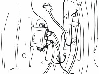
- Route the switch and electrical connection cables along the existing cable harness up to the right-hand tail lamp
- Route the cable together with the buzzer (3) forwards in the car along the right-hand side of the cargo compartment.
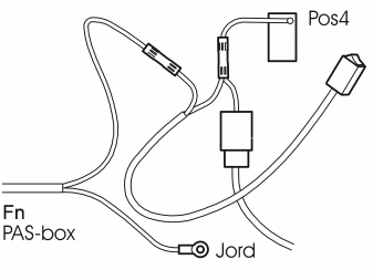
- Cut off the cable which goes to position 4 in the lower grey connector for the tail lamp
- Strip the end of the cable from the PAS box
- Adjust the length of the cable for the switch. Strip the cable ends
- Join the cable from the PAS box to one of the cables from the switch. Use a bonded crimping sleeve from the kit
- Connect the other cable from the switch to the cut cables on the tail lamp. Use a bonded crimping sleeve
- Press the bonded crimping sleeves together. Heat the crimping sleeves until they seal tightly around the cables
- Strip the black cable from the PAS box. Press a ground terminal sleeve onto the cable
- Ground the cable in the existing ground terminal below the tail lamp.
Illustration A
- Take the Velcro strip and the switch from the kit
- Remove the masking tape from the soft Velcro strip. Install the soft Velcro strip on the reverse of the switch. Press it into place
- Take the hard Velcro strip. Press the Velcro strips together on the switch.
Illustration B
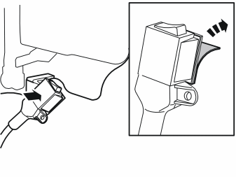
- Clean the panel surface directly below the right-hand tail lamp (viewed from behind). Use a mixture of 30% windscreen washer fluid and 70% water
- Wipe clean and dry
- Remove the masking tape from the hard Velcro strip. Press the switch with the Velcro strips onto the panel. See illustration.
Подсказка: When driving with a trailer, the reverse warning system should be switched off. This is done by pressing the switch to position 0.
Illustration A
- Move both the front seats forward so that the rear seat backrests can be folded down completely
- Remove the head restraints from the rear seat backrests and place them to one side
- Fold the rear seat cushion and backrests forward.
Illustration B
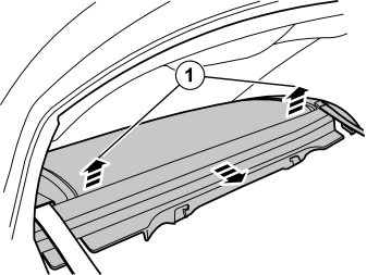
- Lift the parcel shelf straight up until the clips (1) release on both sides
- Pull the parcel shelf backwards
- Position the parcel shelf so that the panel underneath can be accessed.
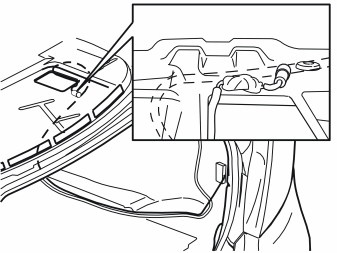
- Connect the buzzer to the cable connector
- Route the cable together with the buzzer along the existing cable harness. Continue up along the right-hand side of the cargo compartment
- Continue to route the cable along the reinforcement panel and up under the parcel shelf
- Secure the cable using butyl tape from the kit
- Route the buzzer cable up through the hole in the parcel shelf. Secure the buzzer. See illustration. It must be possible to reach the buzzer through the air hole in the rear edge of the parcel shelf
- Ensure that the hole in the buzzer is at maximum aperture. This can be adjusted later if the sound level inside the car is too high. However the sound is muted by the parcel shelf and so it is best to start with the maximum volume
- Firmly secure the cable and the buzzer using butyl tape. This is done to prevent rattling.
Finishing work
- Reinstall the parcel shelf. Press its clips into position. Ensure that the top of the buzzer can be turned to alter the volume. (The buzzer is reached through the air hole in the parcel shelf.)
Примечание: The buzzer volume can be regulated by turning the lid to change the size of the sound opening.
- Reinstall the head restraints in the rear seat backrests
- Fold the backrests and cushion back into place.
- Gather together any excess cables. Clamp the cables neatly where they cannot rub or become damaged
- Reinstall the panels and everything else that was removed. Reinstall in the reverse order to how the items were removed
- Check the function of the reverse warning system. Adjust the volume of the buzzer to the desired level
- Check that the reverse warning system can be turned off using the switch.
Обсуждение и оценка
0Пока нет комментариев. Будьте первым.