Применимость
| Модель | Двигатель | Год |
|---|---|---|
| S80 (07-) | — | 2007, 2008 |
| V70 (08-) | — | 2008 |
| XC70 (08-) | — | 2008 |
Примечание: This accessory requires software unique to the car.
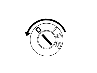
- Turn the ignition switch to position 0.
- Disconnect the battery negative lead.
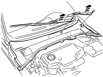
- Remove the wiper arms.
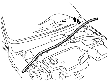
- Detach the cover mouldings at the front edge of the panel over the wiper shafts.
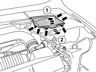
- Remove the front part of the battery box cover.
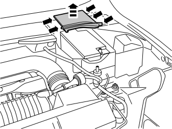
- Remove the rear part of the battery box cover.
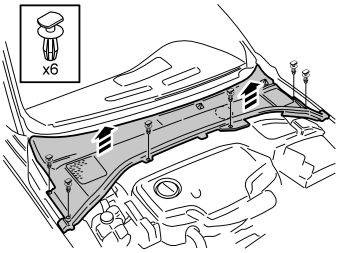
- Remove the clips of the wiper shaft panel and remove the panel.
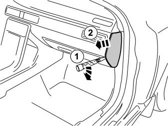
- Remove the right end panel of the dashboard.
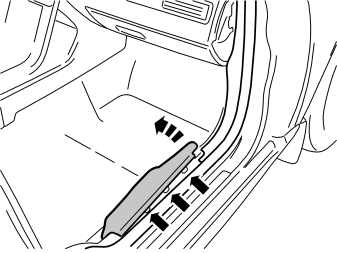
- Remove the sill panel in the right front door by first carefully prising loose the front edge and then pulling up until the three clips release. Then pull forwards/upwards.
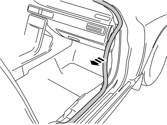
- Detach the rubber moulding in the front edge of the door opening at the bottom A-pillar panel.
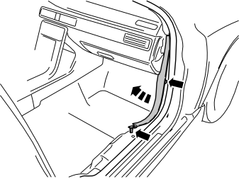
- Remove the lower A-pillar panel at the right front door by first pulling up at the rear edge until the clip releases. Then pull rearward until the centre clip releases. Finally, pull it off at a downward angle from the upper A-pillar panel.
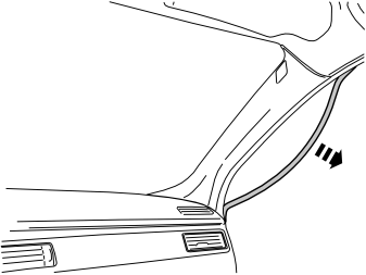
- Detach the rubber moulding at the upper A-pillar panel and the corner of the roof panel.
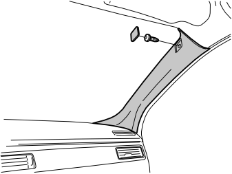
- Remove the cover and bolt of the A-pillar panel.
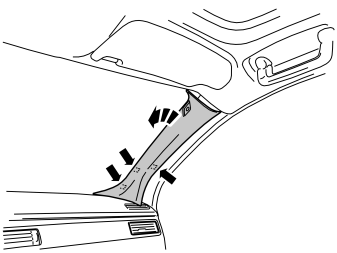
- Carefully remove the A-pillar panel. Starting at the top edge, pull it toward the inside of the car until the three clips on the inside release. Then pull it off.
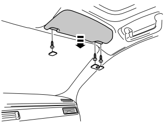
- Remove the cover, bolts and mounting of the left sun visor.
- Unplug the connector of the sun visor and remove it.
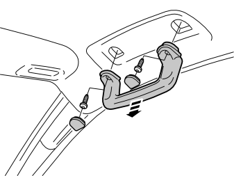
- Carefully prise up the cover and remove the bolts of the courtesy handle.
- Remove the courtesy handle.
Illustration A
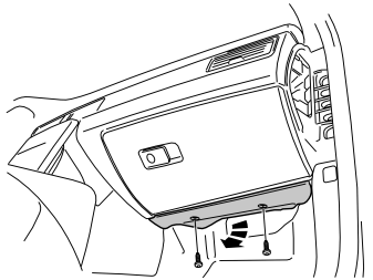
- Remove the bolts of the panel underneath the glovebox and remove it.
Illustration B
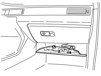
- Unplug the lighting connector and move the panel aside.
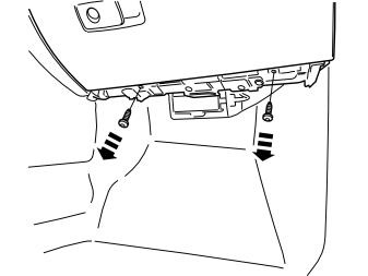
- Remove the two bolts along the bottom edge of the glovebox.
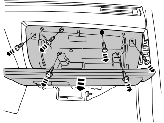
- Remove the seven bolts from the inside of the glovebox.
- Cut the tie strap for the glovebox lighting on the rear.
- Pull out the glovebox a bit and unplug the grey connector on the rear.
- Pull out the glovebox and put it to one side.
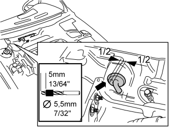
- Drill a Ø 5.5 mm (7/32 ") on the right side of the large rubber grommet as illustrated. Use an angle drill and fit a 5 mm (13/64 ") drill stop.
Примечание: Take care when drilling as many cables go through the rubber grommet.
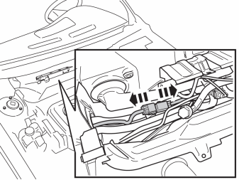
- Unplug the parking heater connectors. These are located on the right side near the large rubber grommet in the bulkhead.
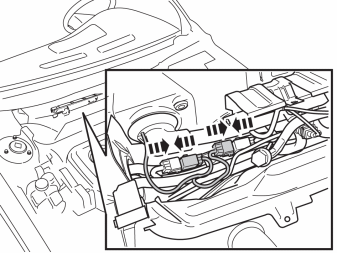
- Take the adapter cable with two large connectors from the kit.
- Insert the cable ends in the hole in the large rubber grommet on the right side of the bulkhead.
- Plug in the adapter cable connectors to the corresponding parking heater cable connectors that were unplugged before.
- Use tie straps from the kit to secure the cables and connectors to existing cables to prevent rattling.
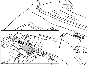
Applies to right-hand drive cars
- Detach the connector from its holder and move it aside.
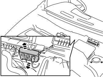
For right-hand drive cars with siren
- Unscrew the nuts of the siren with cover a few turns.
- Remove the siren with cover and move it aside.
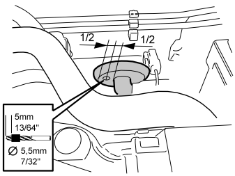
Applies to right-hand drive cars
- Drill a Ø 5.5 mm (7/32 ") on the right side of the large rubber grommet as illustrated. Use an angle drill and fit a 5 mm (13/64 ") drill stop.
Примечание: Be careful not to drill into existing cables, pipes or other components.
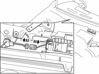
Applies to right-hand drive cars
- Unplug the parking heater connectors. These are located on the right side near the brake servo.
Illustration A
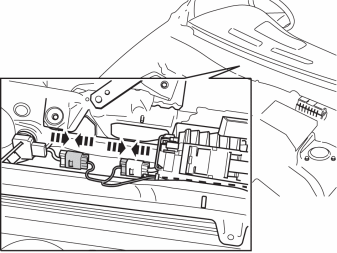
Applies to right-hand drive cars
- Take the adapter cable with two large connectors from the kit.
- Plug in the adapter cable connectors to the corresponding parking heater cable connectors that were unplugged before.
Illustration B
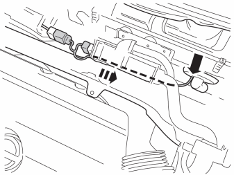
Applies to right-hand drive cars
- Route the cable with the two cable ends to the large rubber grommet on the left side of the bulkhead.
- Insert the cable ends in the hole in the rubber grommet.
- Use tie straps from the kit to secure the cables and connectors to existing cables to prevent rattling.
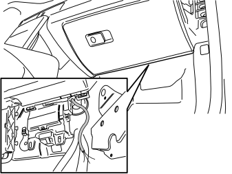
Applies to all models
- Pull the cables through the rubber grommet in the bulkhead.
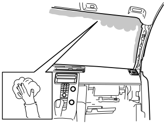
- Clean the marked surface on the inside of the windscreen using isopropanol P/N 1161721 and wipe dry.
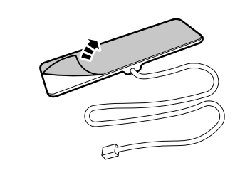
- Remove the protective backing tape from the antenna mounting tape.
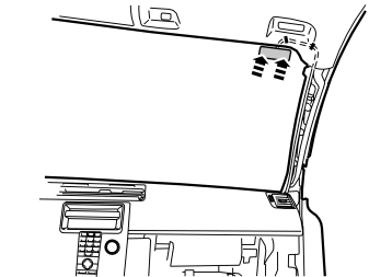
- Press the antenna into place as close to the front edge of the roof panel as possible and route the cable just above the edge of it.
- Carefully bend down the front edge of the roof panel and use pieces of butyl tape to secure the cable at the panel.
Примечание: Do not damage the roof panel.
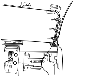
- Route the antenna cable along the existing cable at the A-pillar, in toward the dashboard and down toward the floor.
- Secure the antenna cable at the existing cable harness using three tie straps from the kit.
Примечание: Make sure that the routing of the antenna cable does not interfere with the function of the inflatable curtain.
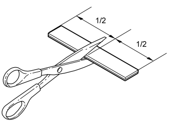
- Remove the Velcro from the kit and cut it in the centre.
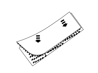
- Press the Velcro pieces together.
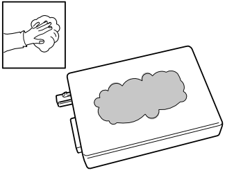
- Wash the plane surface of the receiver unit using isopropanol P/N 1161721 and wipe dry.
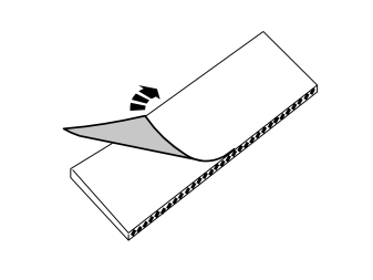
- Remove the protective backing tape from one of the Velcro pieces.
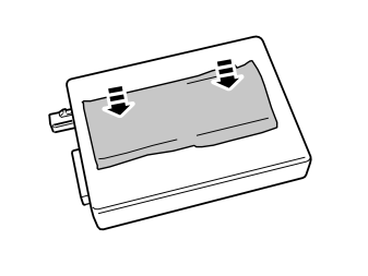
- Press the Velcro onto the receiver unit.
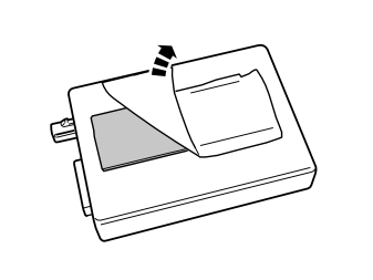
- Remove the protective backing tape from the other Velcro piece.
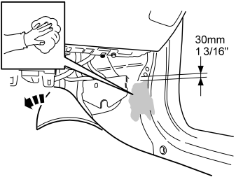
- Move the floor and insulating mats out of the way.
- Scrape away any sealing compound from the plane surface at the bottom edge of the A-pillar where the receiver unit for remote start will sit. The top edge of the receiver unit should be 30 mm (1 3/16 ") from the bottom edge of the lower hole in the body.
- Clean the surface with isopropanol P/N 1161721 and wipe dry.
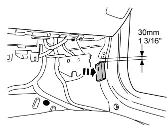
- Press the receiver unit securely into place on the metal surface.
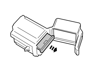
- Carefully loosen the secondary catch in the fuse holder from the kit using a small screwdriver.
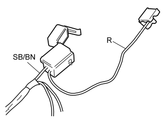
- Take the little red (R) cable with black connector from the kit.
- Connect the routed cable harness and the little red (R) cable with black connector to the fuse holder as illustrated.
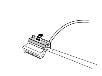
- Carefully loosen the secondary catch of the black six-pin connector using a small screwdriver.
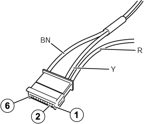
- Connect the yellow (Y) cable to position 2 and the brown (BN) to position 6 in the six-pin connector.

- Connect the connectors to the receiver unit.
Synchronising the transmitter and receiver:
- Put batteries in the transmitter battery compartment.
- Connect the negative battery cable in the car.
- Within 5 seconds, press the "OFF" button on the transmitter for at least 1 seconds. - Synchronisation complete.
- Press the receiver unit onto the Velcro on the body plate if it has loosened.
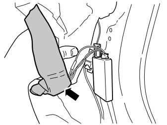
- Wrap foam tape around the fuse holder to prevent rattling.
- Position the fuse holder inside the insulating mat.
- Reposition the insulating and floor mats.
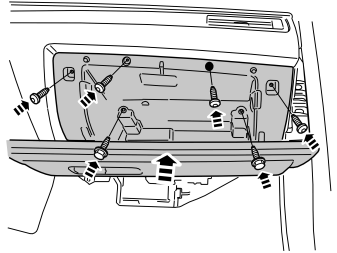
- Reinstall the glovebox and tighten the M6 bolts to 10 Nm (7.5 lbf.ft).
- Plug in the connector on the back of the glovebox and fit a new tie strap to the cable.
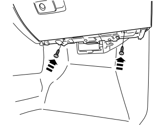
- Carefully fasten the bottom edge of the glovebox with existing bolts.
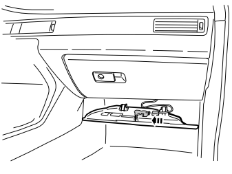
Illustrations A and B
- Plug in the courtesy lighting connector. Refit the panel underneath the glovebox and fasten it with existing bolts.
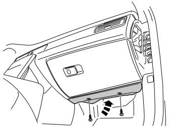
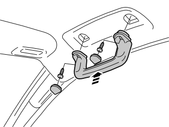
- Reinstall the courtesy handle and tighten the bolts to 10 Nm (7.5 lbf.ft).
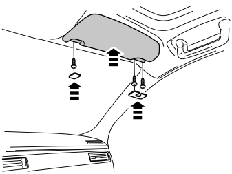
- Take the cover, bolts and left mounting of the sun visor and fasten it.
- Plug in the sun visor connector, reposition it and fasten it with existing bolts.
- Reinstall the cover over the bolts.
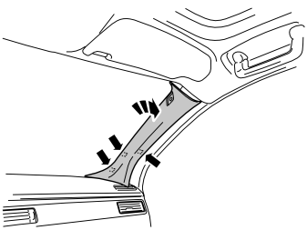
Illustrations A and B
- Reinstall the upper A-pillar panel with bolt and cover.
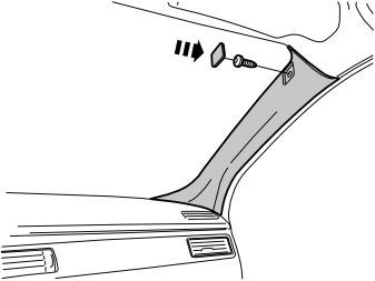
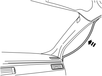
- Reinstall the rubber moulding at the upper A-pillar panel.
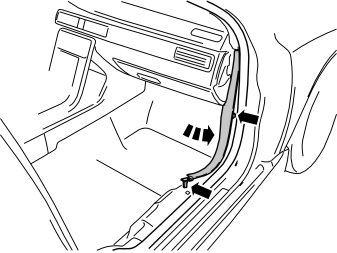
- Reinstall the lower A-pillar panel.
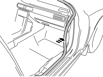
- Reinstall the rubber moulding at the lower A-pillar panel.
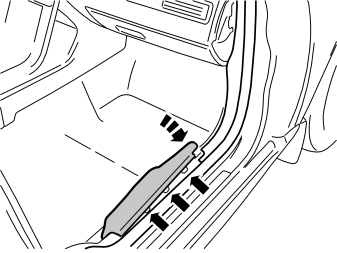
- Reinstall the sill trim panel.
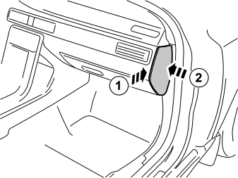
- Reinstall the dashboard end.
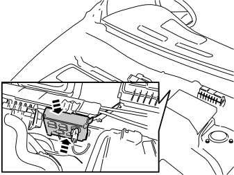
For right-hand drive cars with siren
- Reposition the siren with cover and fasten it.
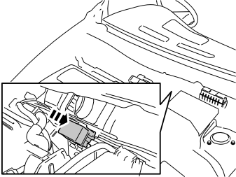
Applies to right-hand drive cars
- Reinstall the connector in its holder.
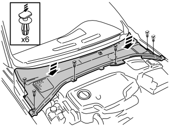
Applies to all models
- Reinstall the panel over the wiper shafts with the six existing clips.
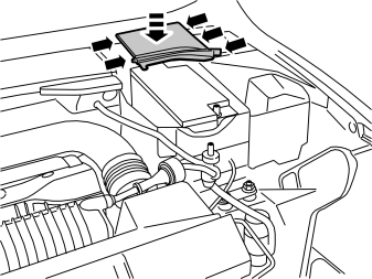
- Reinstall the rear part of the battery box cover.
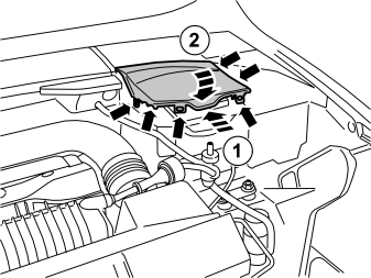
- Reinstall the front part of the battery box cover.
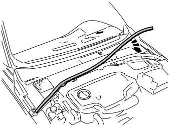
- Reinstall the cover mouldings at the front edge of the panel over the wiper shafts.
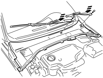
- Reinstall the wiper arms, nuts and cover. Tighten the nuts to 30 ± 3 Nm (22 ± 2 lbf.ft.).
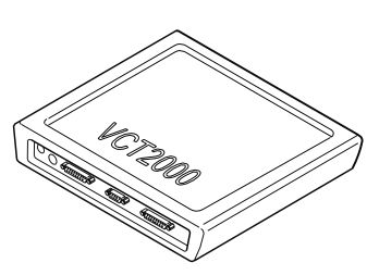
- Programme the software in accordance with the service information in VIDA.
Обсуждение и оценка
0Пока нет комментариев. Будьте первым.