Примечание: - Points 1-17, 41-42 apply to the C70/S70/V70 (-00)
- Points 1, 18-39, 41-42 apply to the S40/V40
- Points 40-42 apply to older models (-1996).
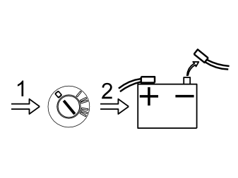
- Turn the ignition key to position 0
- Remove the key from the ignition switch (does not apply to cars with automatic gearboxes)
- Disconnect the battery negative lead.
Примечание: Wait at least five minutes before disconnecting the connectors or removing other electrical equipment.
Applies to C70/S70/V70 (-00)
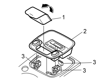
- Open the cover for the ashtray (1). Lift up the ashtray. Place the ashtray to one side
- Pull the panel (2) upwards at the rear edge so that the catches release. Remove the panel. Pull the panel backwards
- Disconnect the connectors (3) for the two switches and the timer
- Place the panel to one side.
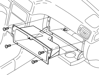
- Remove the glove compartment.
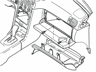
- Remove the soundproofing panel on the passenger side.
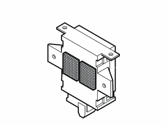
- Clean the marked surface on the remote start module. Use a mild solution of water and windscreen washer fluid (70% / 30%)
- Remove the backing from the Velcro strips. Press the Velcro strips on to the remote start module.
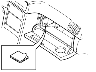
- Clean the flat surface on the heater unit. Use a mild solution of water and windscreen washer fluid (70% / 30%). Measure the distance between the Velcro strips on the remote start module
- Check that the remote start module does not catch on the throttle spindle
- Remove the backing from the Velcro strips. Press the Velcro strips on to the heater unit
- Press the Velcro strips into place properly.
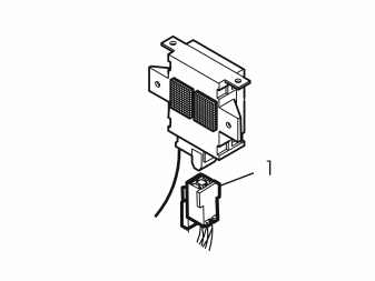
- Remove the cable harness from the kit. Connect the connector to the remote start module.
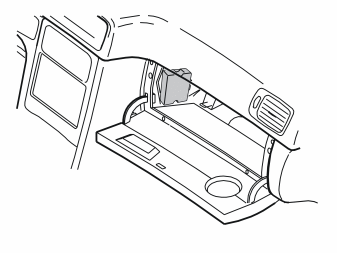
- Press the remote start module on to the Velcro strips.
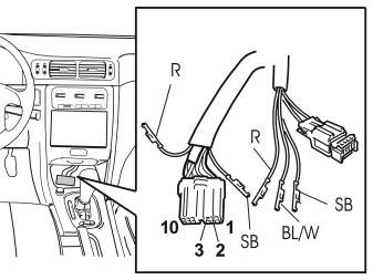
- Route the cable harness with the green connector and the three single cables from the remote start module to the compartment where the timer panel was positioned
- Secure the cable harness at the existing cable harness using the tie straps from the kit
- Open the catch on the green connector for the timer. Disconnect the black (SB) cable in terminal 1 and the red (R) cable in terminal 10
- Connect the black (SB) and red (R) cable from the routed cable harness to the corresponding terminals in the green connector for the timer.
Applies to cars with parking heaters
- Disconnect the green (GN) cable in terminal 2 in the timer connector
- Connect the blue and white (BL/W) cable in the pre-routed cable harness to terminal 2 in the timer connector
- Press the connector catch together.
Applies to cars with electrical engine block heaters
- Disconnect the red (R) cable in terminal 3 in the timer connector.
Примечание: Mark the cable using a piece of tape. The cable will be later connected to terminal 1 in the four pin green connector.
- Connect the blue and white (BL/W) cable in the pre-routed cable harness to terminal 3 in the timer connector
- Press the connector catch together.
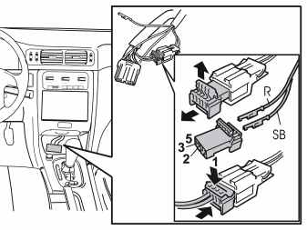
- Disconnect the green connector without wiring from the pre-routed cable harness
-
Open the catch and connect the two cables (previously disconnected from the connector for the timer) as follows:
-
Applies to cars with parking heaters: Connect the green (GN) cable disconnected from terminal 2 in the timer connector, to terminal 1.
-
Applies to cars with electrical engine block heaters: Connect the red (R) cable (marked with tape) disconnected from terminal 3 in the timer connector, to terminal 1.
-
Press the catch together on the connector. Reinstall
- Pull up the thin aerial cable and the cable with the indicator lamp to the compartment where the glove compartment was positioned
- Reinstall the connectors for the switches and the timer.
- Press the panel into place
- Reinstall the ashtray.
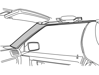
- Detach the right-hand A-post panel. First start at the top edge of the door frame, carefully pull off the panel so that the clips on the inside release
- Then continue downwards. Pull the panel off until all the clips have released
- Carefully pull up the end of the A-post panel from the mounting in the dashboard.
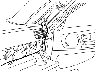
- Pull the thin aerial cable in from the remote start module. Route the cable up to the rear edge of the right-hand A-post as illustrated.
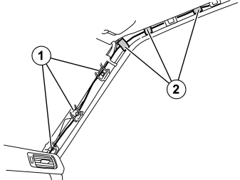
- Pull the aerial cable along the right-hand A-post. Insert the cable through the three existing clamps (1)
- Route along the top edge of the door frame to the rear edge.
- Tape the aerial cable at the door frame using three pieces of tape (2)
- Reinstall the A post panel. Ensure that the no cables are trapped
- Clamp the excess cable for the aerial. Also secure at the existing cable harnesses inside the glove compartment using two tie straps from the kit.
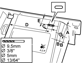
- Take measurements on the glove compartment to make holes for the indicator lamp and clips as illustrated:
- Drill two 5 mm (13/64”) diameter holes for the clip. Cut between the holes
- First drill using a 5 mm diameter (13/64”) drill bit. Then use a 9.5 mm (3/8”) drill bit for the indicator lamp lead-in. Drill the hole in the centre of the radius on the glove compartment
- Remove any swarf.
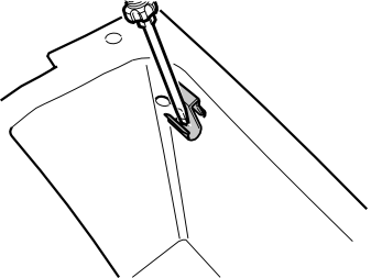
- Press the clip (from the kit) in the oval hole in the glove compartment. Use a screwdriver to press it into place.
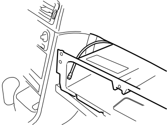
- Pull up the cable with the indicator lamp to the cut-out for the glove compartment. Insert the cable through the drilled hole
- Clamp the excess cable inside the glove compartment using a tie strap from the kit.
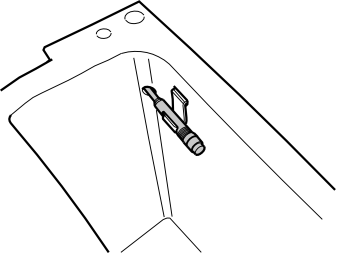
- Press the indicator lamp into the clip
- Reinstall the glove compartment. Ensure that wiring is not trapped
- Connect the connector to the floor lighting in the soundproofing panel
- Reinstall the soundproofing panel.
Applies to S40/V40
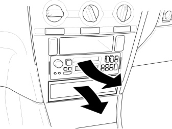
- Press in the catches on the sides. Pull the radio out
- Disconnect the connectors from the radio. Place the radio to one side
- Remove the storage compartment under the radio if applicable.
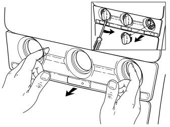
Applies to cars with manual climate control
- Remove the heater controls
- Remove the front panel. Some force is required.
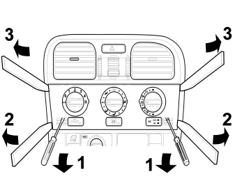
Applies to cars with automatic climate control
- Press the catches behind the panel upwards through the holes in the air conditioning (A/C) panel
- at the same time pull the lower edge of the panel towards you using a weatherstrip tool
- Press the entire panel upwards slightly. Carefully pull the top of the panel towards you (the panel may be securely positioned). The controls remains on the heater control panel.
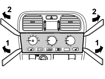
Applies to cars with electronic climate control
- Carefully pry between the lower edge of the dashboard and the heater control panel. Use a weatherstrip tool. Carefully pry the lower edge of the panel out towards you
- Press the entire panel upwards slightly. Carefully pry the top of the panel towards you (the panel may be securely positioned).
- Remove the panel.
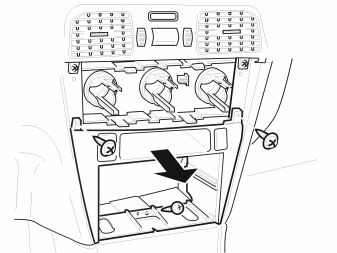
- Remove the three screws from the centre console panel
- Pull the panel out. Disconnect any connectors. Place the panel to one side.
- Clean the marked surface on the remote start module. Use a mild solution of water and windscreen washer fluid (70% / 30%)
- Remove the backing from the Velcro strips. Press the Velcro strips on to the remote start module.
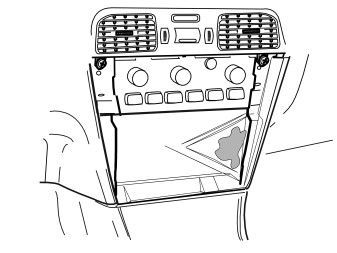
- Clean the marked surface on the right-hand side of the centre console. Use a mild solution of water and windscreen washer fluid (70% / 30%)
- Wipe dry.
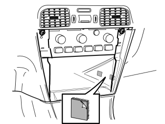
- Measure the distance between the Velcro strips on the remote start module. This is to position the Velcro strips on the right-hand side of the centre console correctly
- Remove the backing from the remaining Velcro strips. Securely press the Velcro strips on to the inside right of the centre console.
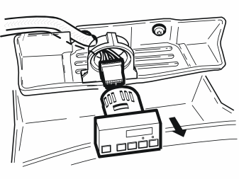
- Remove the timer from the bracket
- Remove the connector from the timer.
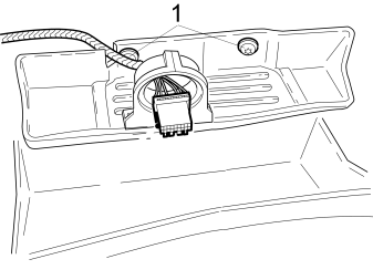
- Remove the two screws (1). Remove the coin tray and bracket by pulling the top edge and lifting out.
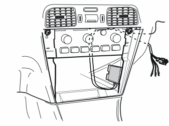
- Take the remote start module and cable harness from the kit
- Connect the cable harness to the remote start module
- Press the remote start module against the installed Velcro strips on the inside of the centre console
- Pull the cable harness with the green connector, the cable and indicator lamp and the aerial cable up under the dashboard to the right-hand side of the centre console. Pull the cables out from the existing holes for the cable for the timer, on the left-hand side of the glove compartment.
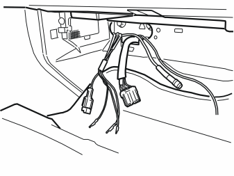
- Route the wiring routed from the remote start module. Position the wiring in the glove compartment.
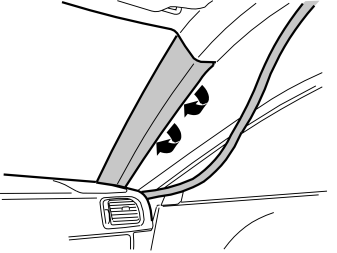
- Pull off the rubber strip from the A-post panel at the front edge of the door opening for the right-hand front door
- Pull off the A-post panel starting at the top edge. Then pull downwards until the two clips on the inside have released. Do not damage the roof and A-post panels.
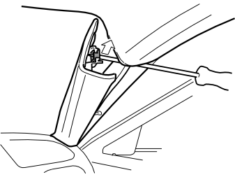
- Remove the two clips on the inside of the A-post panel. Use a screwdriver that is slightly thinner than the hole in the clip to release the clip. Carefully turn the clips both ways so that the catches are raised. At the same time move the clip outwards and upwards. Press the lower clip downwards in the same way
- Pull out the A-post panel from the mounting in the dashboard. Place to one side.
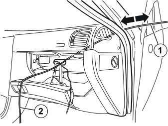
- Insert a curtain wire (1) or similar in the lower edge of the dashboard on the right-hand side of the A-post panel mounting. Pull the curtain wire out of the hole in the glove compartment where the pre-routed wiring is positioned
- Tape up the end of the thin aerial cable (2). Pull the cable end up on top of the dashboard.
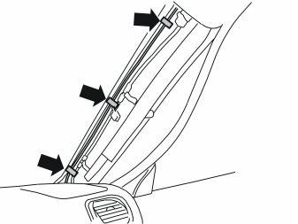
- Route the cable along the A-post to the start of the headlining
- Tape the aerial cable at the front edge of the A-post.
Примечание: Do not tape the aerial cable to the inflatable curtain if the car is so equipped.
- Reinstall the A post panel
- Reinstall the rubber strip in the door opening.
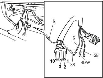
- Open the catch on the green connector for the timer. Disconnect the black (SB) cable from terminal 1 and the red (R) cable from terminal 10
- Connect the black (SB) and red (R) cable from the routed cable harness to the corresponding terminals in the green connector for the timer.
Applies to cars with parking heaters
- Disconnect the green (GN) cable in terminal 2 in the timer connector
- Connect the blue and white (BL/W) cable in the pre-routed cable harness to terminal 2 in the timer connector
- Press the connector catch together.
Applies to cars with electrical engine block heaters
- Disconnect the red (R) cable in terminal 3 in the timer connector.
Примечание: Mark the cable using a piece of tape. The cable will be later connected to terminal 1 in the four pin green connector.
- Connect the blue and white (BL/W) cable in the pre-routed cable harness to terminal 3 in the timer connector
- Press the connector catch together.
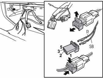
- Disconnect the green connector without wiring from the pre-routed cable harness
-
Open the catch and connect the two cables (previously disconnected from the connector for the timer) as follows:
-
Applies to cars with parking heaters: Connect the green (GN) cable disconnected from terminal 2 in the timer connector, to terminal 1.
-
Applies to cars with electrical engine block heaters: Connect the red (R) cable (marked with tape) disconnected from terminal 3 in the timer connector, to terminal 1
- Press the catch together on the connector. Reinstall.
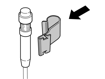
- Press the small clip (from the kit) on to the indicator lamp.
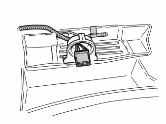
- Insert all excess cable and the small green connector in the hole where the wiring was routed
- Reinstall the coin tray. Tighten the coin tray using the left-hand screw
- Press the clip with the indicator lamp in the edge of the coin tray, on the right-hand side of the timer bracket.
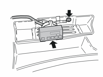
- Install and tighten the right-hand screw in the timer bracket
- Connect the connect to the timer. Press into the bracket
- Insert any cable excess in the lead-in in the coin tray.
- Reinstall the centre console panel and any connectors
- Reinstall the heater control panel and any control switches
- Connect the connectors to the radio. Reinstall the radio
- Where appropriate: Reinstall the storage compartment under the radio
- Reinstall the panel under the dashboard.
Applies to older models (-1996)
Illustration A
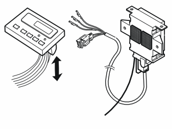
- On older models (1996 and older), install the bracket with the remote start module in a suitable position under the dashboard
- Position the indicator lamp in an accessible position so that components do not have to be removed
- Position the aerial cable behind the A-post panel as on newer cars. See the previous points
- Clamp the wiring using tie straps from the kit.
Illustration B
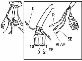
- Remove the green connector from the timer
- Open the catch on the green connector. Disconnect the black (SB) cable from terminal 1 and the red (R) cable from terminal 10
- Connect the black (SB) and red (R) cable from the routed cable harness to the corresponding terminals in the green connector for the timer.
Applies to cars with parking heaters
- Disconnect the green (GN) cable in terminal 2 in the timer connector
- Connect the blue and white (BL/W) cable in the pre-routed cable harness to terminal 2 in the timer connector
- Press the connector catch together.
Applies to cars with electrical engine block heaters
- Disconnect the red (R) cable in terminal 3 in the timer connector.
Примечание: Mark the cable using a piece of tape. The cable will be later connected to terminal 1 in the four pin green connector.
- Connect the blue and white (BL/W) cable in the pre-routed cable harness to terminal 3 in the timer connector
- Press the connector catch together.
Illustration C
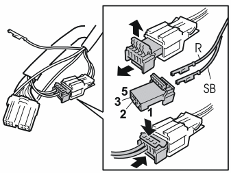
- Disconnect the green connector without wiring from the pre-routed cable harness
-
Open the catch and connect the two cables (previously disconnected from the connector for the timer) as follows:
-
Applies to cars with parking heaters: Connect the green (GN) cable disconnected from terminal 2 in the timer connector, to terminal 1.
-
Applies to cars with electrical engine block heaters: Connect the red (R) cable (marked with tape) disconnected from terminal 3 in the timer connector, to terminal 1
- Press the catch together on the connector. Reinstall
- Reinstall the connector in the timer.
Applies to all models
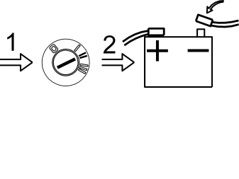
- Turn the ignition key to position II
- Reconnect the battery negative lead
- Enter the anti-theft radio code.
- Test the function according to the accessory manual
- Return the accessory manual to the customer.
Обсуждение и оценка
0Пока нет комментариев. Будьте первым.