Применимость
| Модель | Двигатель | Год |
|---|---|---|
| C70 (06-) | — | 2006–2013 |
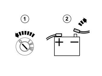
- Turn the ignition switch to position 0.
- Disconnect the battery negative lead.
Примечание: Wait at least three minutes before unplugging the connectors or removing other electrical equipment.
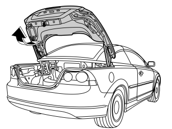
- Open the boot lid/tailgate.
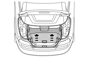
- Lift up the cargo compartment divider.
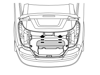
Remove:
- the cover of the toolbox.
- the spare wheel, if in place.
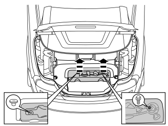
- Take the tools out of the toolbox.
Remove:
- the clip.
- the screw.
- the toolbox.
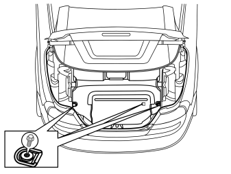
- Remove the three screws and the lashing eyes from the floor.
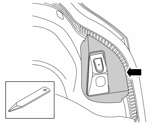
- Remove the cover from the trunk lid stop. Use a weatherstrip tool to pry between the cover and the stop to release the catches.
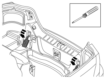
- Remove the two light bulbs by pressing in the two catches at the top with a screwdriver.
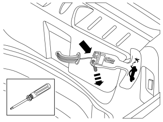
For cars with emergency release handle in cargo compartment
- Remove the emergency release handle by pressing out the pin at the eye and unhooking the cable.
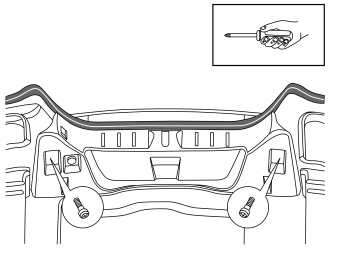
- Remove the two screws in the sill moulding.
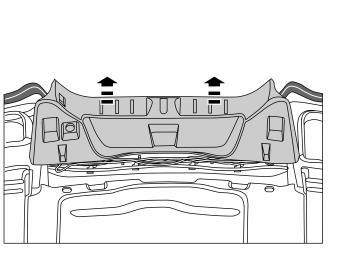
- Remove the sill moulding by pulling it upward until the clips release. Move the sill moulding aside.
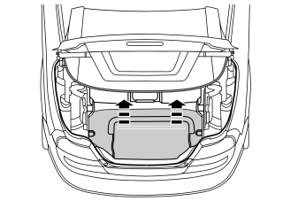
- Remove the cargo compartment carpeting.
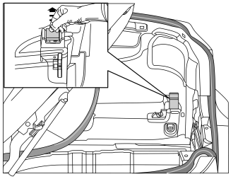
- Remove the rubber stop on the roof's stop brace.
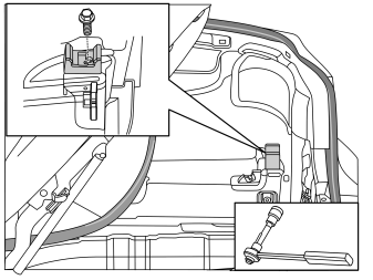
- Mark out the roof's stop brace in relation to the screw.
- Remove the screw and the roof's stop brace.
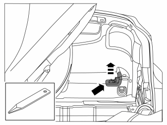
- Remove the load divider lock by using a weatherstrip tool to pry between the carpet and lock.
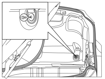
- Remove the screw and the lashing eye on the right side.
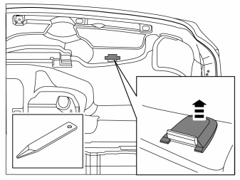
- Remove the stop brace cover.
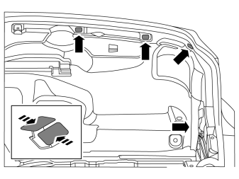
- Undo the four clips on the side panel.
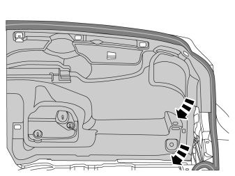
- Fold out the side panel to access the accessory electronic module (AEM).
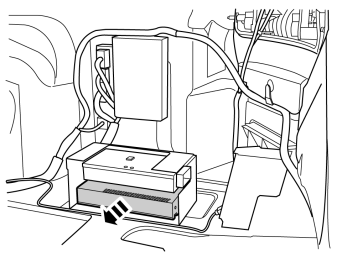
- Remove the accessory electronic module (AEM).
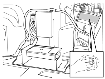
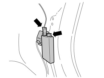
- Clean the marked surface on the inside of the rear window using isopropanol, P/N 1161721, and wipe dry.
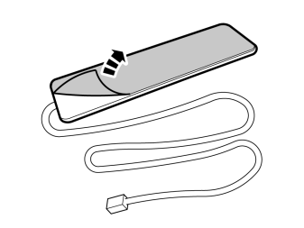
- Remove the protective backing tape from the antenna mounting tape.
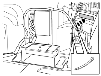
- Press the antenna into place on the flat panel surface just below the right hand tail lamp as illustrated.
- Secure the cable at the existing cable harness.
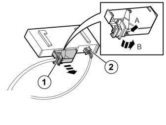
- Disconnect the large connector (1) from the accessory electronic module (AEM). First press in the catch (A). Pull the black locking handle (B) in the direction of the arrow until a click is heard.
- Disconnect the connector from the accessory electronic module (AEM).
- Disconnect the connector (2) from the accessory electronic module (AEM).
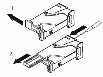
Remove:
- the black catch (1) holding the black switch in place in the connector by pulling in the direction of the arrow.
- the black switch (2) by inserting a pointed object in the hole in the other end. Press out.
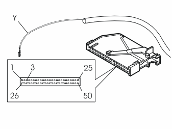
- Connect the yellow cable from the control module to terminal 3 in the accessory electronic module (AEM) connector.
Примечание: The numerical markings on the top and bottom of the black terminal pin are extremely small, so be careful when installing the cable.
Reinstall:
- the black switch in the connector. Lock it into place using the catch.
- the connector into the accessory electronic module (AEM). Secure using the black locking handle.
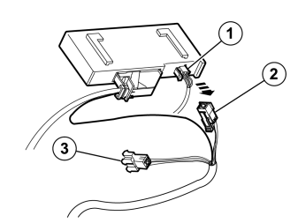
- Connect the connector (2) to the accessory electronic module (AEM).
- Connect the remaining connector (3) on the T-cable to the connector that was disconnected from the accessory electronic module (AEM).
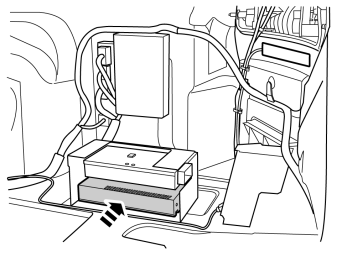
- Reinstall the accessory electronic module (AEM).
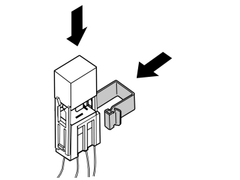
- Take the relay and the large clip from the kit.
- Press the relay into the relay holder.
- Press the clip into the relay holder.
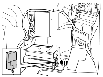
- Press in the relay at the edge of the plate.
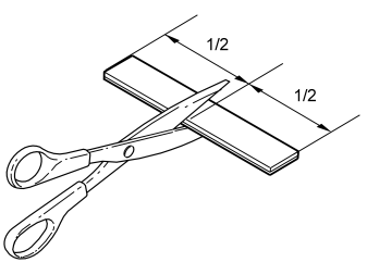
- Remove the Velcro from the kit and cut it in the centre.
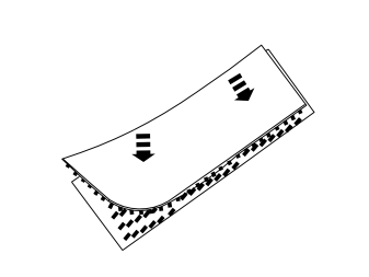
- Press the Velcro pieces together.
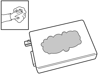
- Wash the plane surface of the receiver unit using isopropanol P/N 1161721 and wipe dry.
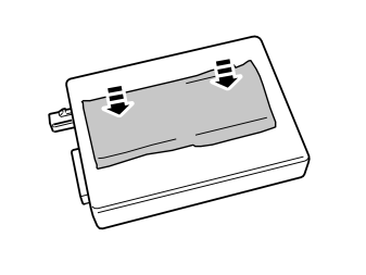
- Press the Velcro onto the receiver unit.
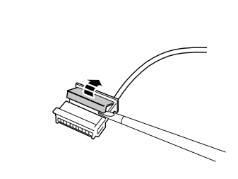
- Carefully loosen the secondary catch of the black six-pin connector from the kit using a small screwdriver.
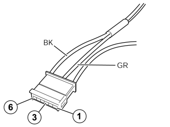
- Connect the green (GN) cable from the kit to terminal 3, and the black (BK) cable to terminal 6 in the six pin connector.
- Press the secondary catch into place on the black six pin connector.
- 1 - Connect the negative battery cable in the car.
- 2 - Put batteries in the transmitter battery compartment.
- 3 - Connect the connector and antenna cable to the receiver unit.
- 4 - Within 5 seconds, press the "OFF" button on the transmitter until the LED goes out. Synchronization complete.
- Press the receiver unit onto the Velcro on the body plate if it has loosened.
Примечание: Tape up any excess cable and place it beside the control module.
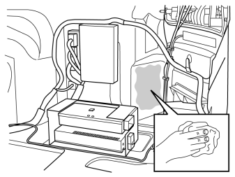
- Clean the marked surface on the inside of the smooth panel surface using isopropanol, part no. 1161721, and wipe dry.
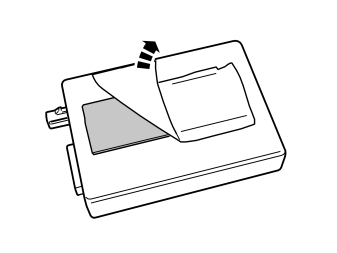
- Remove the protective backing tape from the other Velcro piece.
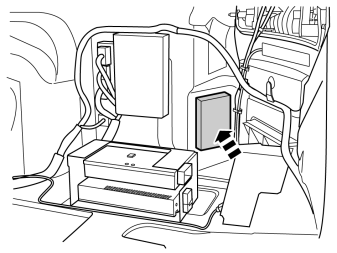
- Press the receiver unit securely into place on the smooth surface on the rear wing.

Reinstall:
- the side panel.
- stops and attaching braces.
- the cargo compartment carpeting.
- the sill panel with lighting.
- any emergency release.
- the stop for the boot lid/tailgate.
- the lashing eyes; tighten the screws to 24 Nm (17 lbf.ft.).
- the toolbox.
-
the divider.
-
Programme the software in accordance with the service information in VIDA.
- Test the function according to the accessory manual.
Обсуждение и оценка
0Пока нет комментариев. Будьте первым.