Применимость
| Модель | Двигатель | Год |
|---|---|---|
| S40 (04-) | — | 2004–2011 |
| V50 | — | 2004–2011 |
- Turn the ignition switch to position 0.
- Remove the ignition key from the ignition switch.
Примечание: Wait at least five minutes before disassembling the connectors or removing other electrical equipment.
Steps 2–36 apply to the V50
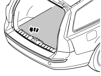
- Remove the cargo compartment carpet.
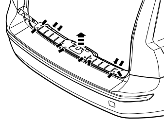
Removing the sill trim panel from the tailgate:
- Prize off the four external clips at the front edge/bottom edge of the sill trim panel on the tailgate.
- Pry up one of the corners of the sill trim panel so that the two clips at that end release. Use a weatherstrip tool.
- Pull up the sill trim panel so the remaining six clips release. Remove the panel.
Removing the rubber seal for the tailgate:
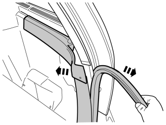
- Detach the rubber strip where it covers the right-hand side panel in the boot opening.
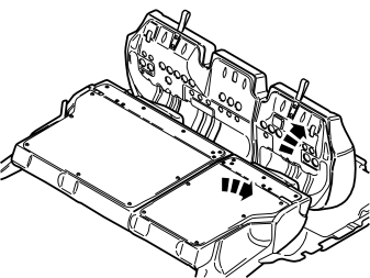
- Removing the rubber seal for the tailgate:
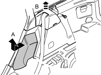
Removing the side cushion:
- Grasp the upper edge of the right-hand side cushion. Pull the side cushion forward so that the clip on the reverse releases.
- Slide the side cushion upwards.
Removing the panel at the front/top of the side panel:
- Remove the screw at the rear edge of the panel at the front/top of the right-hand side panel.
- Pull the panel upwards so that the four clips on the inside release.
- Pull off the rubber strip at the rear of the opening for the right-hand rear door.
Removing the lower panel on the C-post:
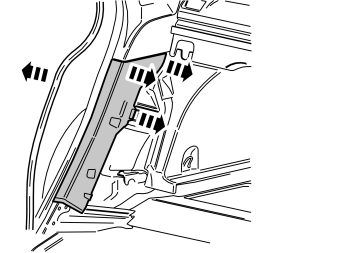
- Carefully pry off the lower panel on the C-post on the right-hand side. Carefully pry at the top edge. Use a plastic weatherstrip tool.
- Pull the panel on the C-post so that the two upper clips release. Then continue pulling downwards until the last two clips release.
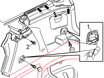
Removing the side panel:
- Fold out the load securing eyelets on the right-hand side panel.
- Insert a scriber with an angled tip into the holes in the top of the covers (1). Turn the scriber so that the tip engages the reverse of the cover. Pull the covers off.
- Remove the screws in the load securing eyelets.
- Remove the screw (2) at the front/top edge of the side panel.
- Pull off the side panel at the top so that the two clips at the rear/bottom of the side window and the clip at the bottom of the D-post release.
- Disconnect the connector for the 12V socket, if present.
- Disconnect the connector for the 12V socket, if present.
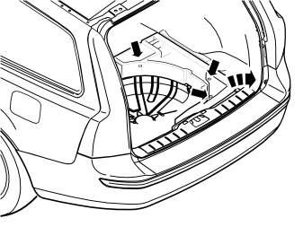
- Remove the right-hand floor support. First remove the three clips at the bottom of the compartment, then lift it up.
Applies to cars with Parking Assistance Module (PAM)
- Remove the parking assistance module (PAM) with cables from behind the right-hand rear wheel arch.
- If necessary: disconnect any surrounding wiring.
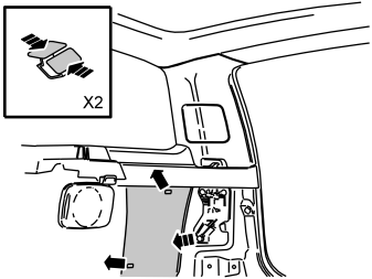
- Remove the insulation panel. The insulation panel is secured with two clips.
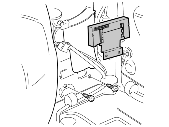
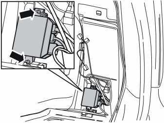
- Remove the accessory electronic module (AEM). It is secured with 2 screws.
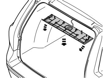
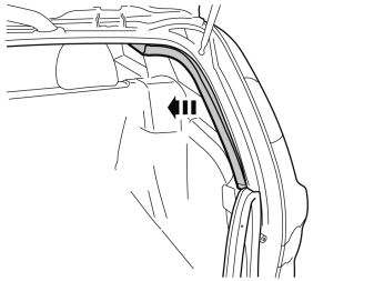
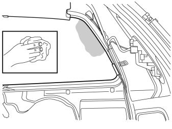
- Clean the marked surface on the inside of the rear window using isopropanol, P/N 1161721, and wipe dry.
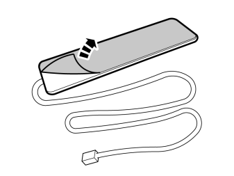
- Remove the protective backing tape from the antenna mounting tape.
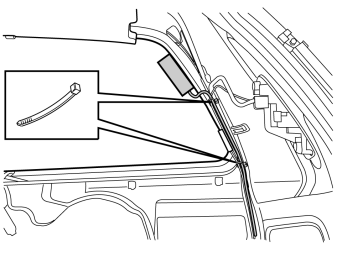
- Press the antenna onto the inside of the window, as close to the panel edge as possible.
- Secure the cable at the existing cable harness.
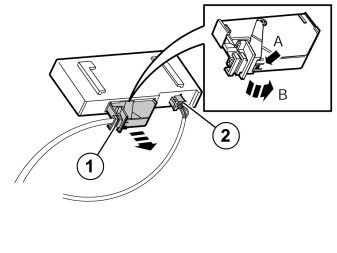
- Disconnect the large connector (1) from the accessory electronic module (AEM). First press in the catch (A). Pull the black locking handle (B) in the direction of the arrow until a click is heard.
- Disconnect the connector from the accessory electronic module (AEM).
- Disconnect the connector (2) from the accessory electronic module (AEM).
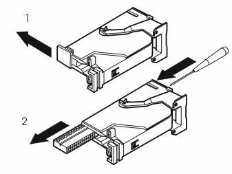
Remove:
- the black catch (1) holding the black switch in place in the connector by pulling in the direction of the arrow.
- Remove the black switch (2) by inserting a pointed object in the hole in the other end. Press out.
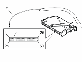
- Connect the yellow cable from the control module to terminal 3 in the accessory electronic module (AEM) connector.
Примечание: The numerical markings on the top and bottom of the black terminal pin are extremely small, so be careful when installing the cable.
Reinstall:
- the black connector socket in the connector. Lock it into place using the catch.
- the connector into the Accessory Electronic module (AEM). Secure using the black locking handle.
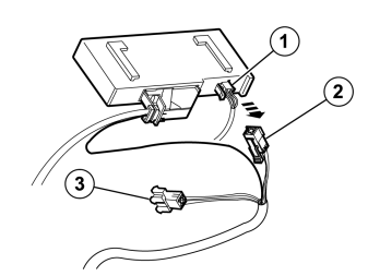
- Connect the connector (2) to the accessory electronic module (AEM).
- Connect the remaining connector (3) on the T-cable to the connector that was disconnected from the accessory electronic module (AEM).
- Reinstall the accessory electronic module (AEM) using the two screws and tighten.
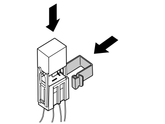
- Take the relay and the large clip from the kit.
- Press the relay into the relay holder.
- Press the clip on the relay holder.
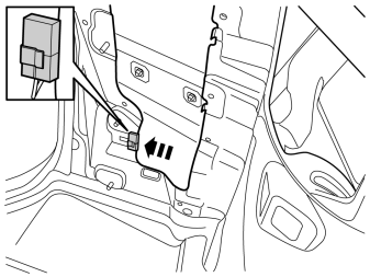
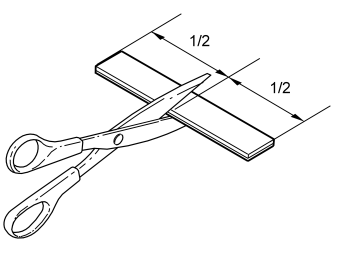
- Remove the Velcro from the kit and cut it in the centre.
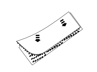
- Press the Velcro pieces together.
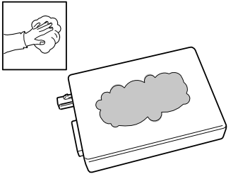
- Wash the plane surface of the receiver unit using isopropanol P/N 1161721 and wipe dry.
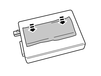
- Press the Velcro onto the receiver unit.
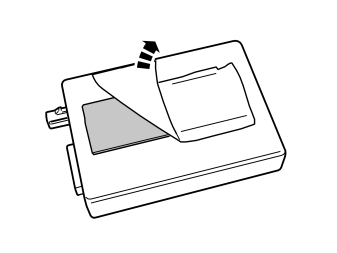
- Remove the protective backing tape from the other Velcro piece.
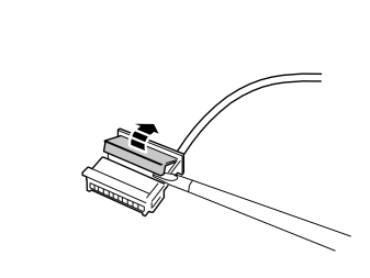
- Carefully loosen the secondary catch of the black six-pin connector from the kit using a small screwdriver.
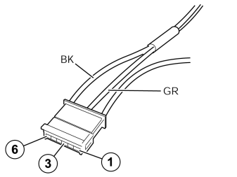
- Connect the green (GN) cable from the kit to terminal 3, and the black (BK) cable to terminal 6 in the six pin connector.
- Press the secondary catch into place on the black six pin connector.
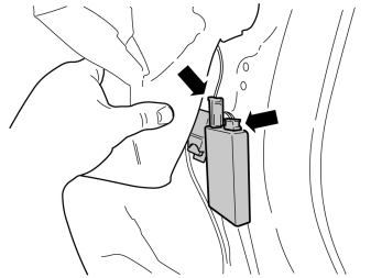
Synchronizing the Transmitter - Receiver
- 1 - Connect the negative battery cable in the car.
- 2 - Put batteries in the transmitter battery compartment.
- 3 - Connect the connector and antenna cable to the receiver unit.
- 4 - Within 5 seconds, press the "OFF" button on the transmitter until the LED goes out. Synchronization complete.
- Press the receiver unit onto the Velcro on the body plate if it has loosened.
Примечание: Tape up any cable excess from the timer relay and place next to the control module under the insulation.
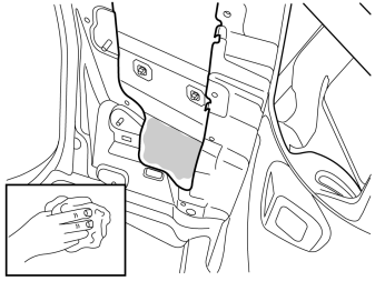
- Clean the marked surface on the inside of the smooth panel surface using isopropanol, part no. 1161721, and wipe dry.
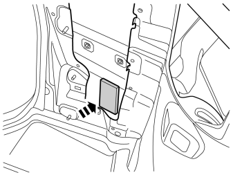
- Press the receiver unit securely into place on the smooth surface on the rear wing.
- If applicable, reinstall the parking assistance module (PAM) and all panels.

- Programme the software in accordance with the service information in VIDA.
- Test the function according to the accessory manual.
Steps 37 – 68 apply to the S40 (04-)
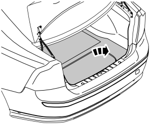
- Remove the cargo compartment carpet.
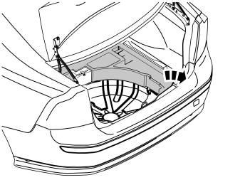
- Remove the upper floor supports on the right and left-hand sides if applicable.
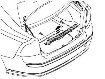
Removing the sill trim panel from the tailgate:
- Prize off the two external clips at the front edge/bottom edge of the sill trim panel on the tailgate.
- Pry up one of the corners of the sill trim panel using a weatherstrip tool so that the two clips at that end release.
- Pull up the sill trim panel at the other end so that the remaining two clips release. Remove the sill trim panel.
Removing the rubber seal for the tailgate:
- Detach the rubber strip where it covers the right-hand side panel in the boot opening.
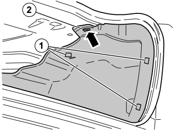
- Unhook the side panel (2) from the mounting on the underside of the parcel shelf.
- Disconnect the connector for the 12V socket, if present.
- Unhook the side panel from the load securing eyelets (1). Remove the side panel.
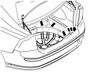
- Remove the right-hand lower floor support. First remove the three clips at the bottom of the compartment, then lift it up.
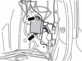
- Remove the parking assistance module (PAM) with cables from behind the right-hand rear wheel arch.
- If necessary, disconnect any surrounding wiring.
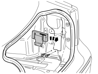
- Remove the accessory electronic module (AEM). It is secured with 2 screws.
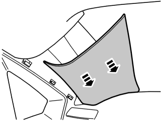
- Remove the upper panel. Pull the panel straight inwards into the vehicle.
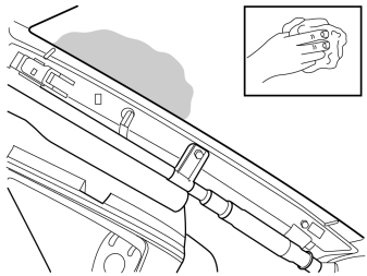
- Clean the marked surface on the inside of the rear window using isopropanol, P/N 1161721, and wipe dry.
- Remove the protective backing tape from the antenna mounting tape.
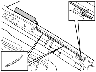
- Press the antenna onto the inside of the window, as close to the panel edge as possible
- Secure the cable at the existing cable harness.
- Tape the cable harness as illustrated so that it is protected against wear from the panel's guide.
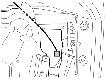
- Pull the cable down into the cargo compartment as illustrated.
- Disconnect the large connector (1) from the accessory electronic module (AEM). First press in the catch (A). Pull the black locking handle (B) in the direction of the arrow until a click is heard.
- Disconnect the connector from the accessory electronic module (AEM).
- Disconnect the connector (2) from the accessory electronic module (AEM).
Remove:
- the black catch (1) holding the black switch in place in the connector by pulling in the direction of the arrow.
- Remove the black switch (2) by inserting a pointed object in the hole in the other end. Press out.
- Connect the yellow cable from the control module to terminal 3 in the accessory electronic module (AEM) connector.
Примечание: The numerical markings on the top and bottom of the black terminal pin are extremely small, so be careful when installing the cable.
Reinstall:
- the black connector socket in the connector. Lock it into place using the catch.
- the connector into the Accessory Electronic module (AEM). Secure using the black locking handle.
- Connect the connector (2) to the accessory electronic module (AEM).
- Connect the remaining connector (3) on the T-cable to the connector that was disconnected from the accessory electronic module (AEM).
- Reinstall the accessory electronic module (AEM) using the two screws and tighten.
- Take the relay and the large clip from the kit.
- Press the relay into the relay holder.
- Press the clip on the relay holder.
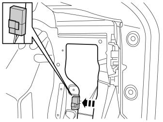
- Press the relay in on the panel edge.
- Remove the Velcro from the kit and cut it in the centre.
- Press the Velcro pieces together.
- Wash the plane surface of the receiver unit using isopropanol P/N 1161721 and wipe dry.
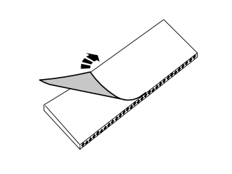
- Remove the protective backing tape from one of the Velcro pieces.
- Press the Velcro onto the receiver unit.
- Carefully loosen the secondary catch of the black six-pin connector from the kit using a small screwdriver.
- Connect the green (GR) cable from the kit to terminal 3, and the black (BK) cable to terminal 6 in the six pin connector.
- Press the secondary catch into place on the black six pin connector
Synchronizing the Transmitter - Receiver
- 1 - Connect the negative battery cable in the car.
- 2 - Put batteries in the transmitter battery compartment.
- 3 - Connect the connector and antenna cable to the receiver unit.
- 4 - Within 5 seconds, press the "OFF" button on the transmitter until the LED goes out. Synchronization complete.
- Press the receiver unit onto the Velcro on the body plate if it has loosened.
Примечание: Tape up any cable excess from the timer relay and place next to the control module under the insulation.
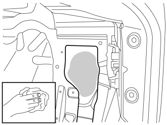
- Clean the marked surface on the inside of the smooth panel surface using isopropanol, P/N 1161721, and wipe dry.
- Remove the protective backing tape from the other Velcro piece.
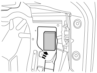
- Press the receiver unit securely into place on the smooth surface on the rear wing.
- If applicable, reinstall the parking assistance module (PAM) and all panels.
- Programme the software in accordance with the service information in VIDA.
- Test the function according to the accessory manual.
Обсуждение и оценка
0Пока нет комментариев. Будьте первым.