Применимость
| Модель | Двигатель | Год |
|---|---|---|
| C30 | — | 2007–2011A |
| C70 (06-) | — | 2006–2011A |
| S40 (04-) | — | 2006–2011 |
| V50 | — | 2006–2011 |
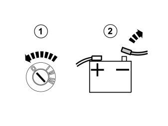
- Turn the ignition switch to position 0.
- Disconnect the battery negative lead.
Примечание: Wait at least three minutes before unplugging the connectors or removing other electrical equipment.
Steps 2-25 apply to cars with a 5-cylinder engine
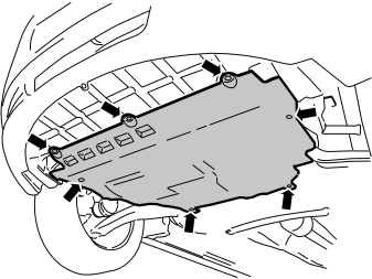
- Turn the seven clips 90°.
- Detach the engine splashguard from the clips and place to one side.
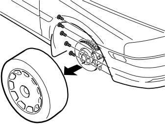
- Remove the right-hand front wheel.
- Remove the five screws holding the bumper cover at the right-hand wing liner.
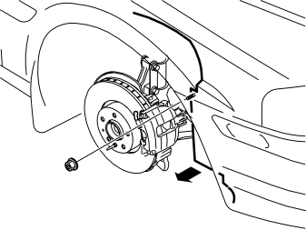
- Remove the nut holding the wing liner at the right-hand front member.
- Bend the front edge of the wing liner up over the brake caliper.
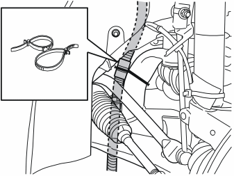
Only applies to cars with an engine block heater
- Cut off the tie strap above the locking sleeve.
- Detach the wiring from the front intake from its clamps, to facilitate installation of the timer relay. If necessary, also detach the cable from the engine block heater.
- Remove the locking sleeve over the cable splice and separate the cables.
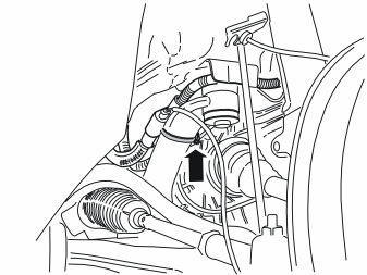
Applies to cars with an engine block heater and passenger compartment connector socket
- Detach the wiring from the front intake from its clamps, to facilitate installation of the timer relay.
- Detach the clamp that holds the junction connector at the stay.
- Remove the junction connector with cables from the clamp and stay.
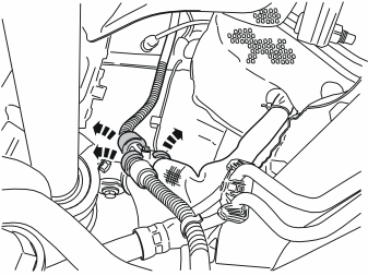
Applies to cars with an engine block heater and passenger compartment connector socket
- Remove the sleeves from above the splices on the cables for the front intake, engine block heater and passenger compartment connector socket.
- Remove the wiring from the junction connector.
- Place the hose clamp and holder with the junction connector to one side. New components are in the kit.
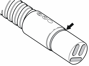
- Lubricate the O-rings on the cable from the front intake, timer relay and cable for passenger compartment connector socket (if applicable). Use low temperature grease (part no. 1161417-9).
Примечание: Do not get any grease on the surfaces of the connector.
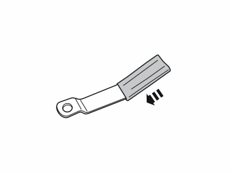
- Take the bracket and rubber guard from the kit (or use the existing one). Press the rubber guard onto the bracket.
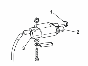
Only applies to cars with an engine block heater
- Take the screw, toothed washer and nut from the kit. Tighten the timer relay at the holder in the position illustrated. The holder must be longitudinally parallel with the timer relay.
- Press the cover (1) (part no. 346509, not included) onto the free socket in the timer relay.
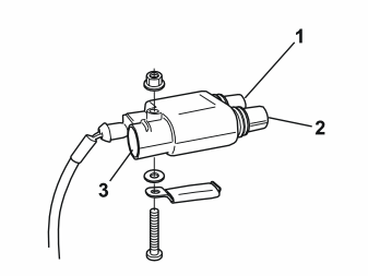
Applies to cars with a passenger compartment connector socket
- Take the screw, toothed washer and nut from the kit. Tighten the timer relay at the holder in the position illustrated. The holder must be longitudinally parallel with the timer relay.
Illustration A
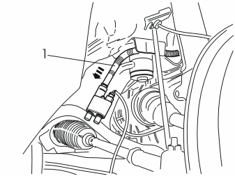
- Connect the front intake cable (1) to the timer relay. Press the cable splice together securely.
Illustration B
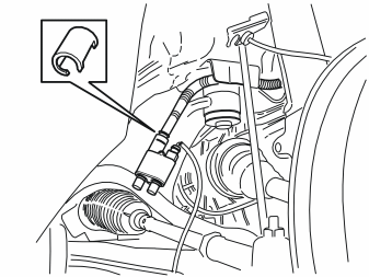
- Press in the existing locking sleeve over the cable splice.
Only applies to cars with an engine block heater
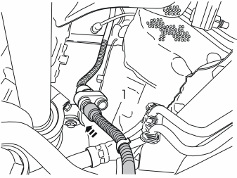
Illustration A
- Connect the cable (1) from the engine block heater to the timer relay. Press the splice together securely.
Illustration B
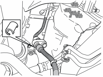
- Press a locking sleeve (from the kit) over the cable splice.
Applies to cars with an engine block heater and passenger compartment connector socket
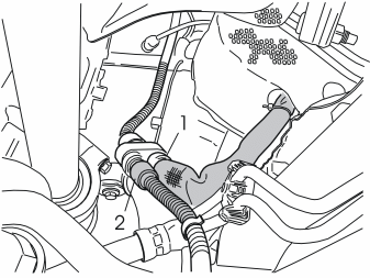
Illustration A
- Connect cable (1) from the passenger compartment connector socket and the cable (2) from the engine block heater to the timer relay.
- Firmly press the splices together.
Illustration B
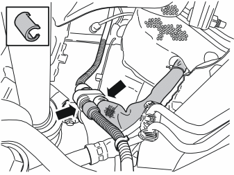
- Press two locking sleeves from the kit and press over the cable splices.
Illustration A
- Install the holder with the connected timer relay with the hose clamp.
Illustration B
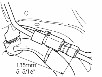
- Check that the same dimensions as in the image are used.
- If the cables for the front intake and engine block heater are disconnected, reinstall them in their clamps.
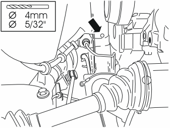
- Route the ground lead from the timer relay.
- Drill a Ø 4 mm (5/32") hole on the underneath of the right-hand front member, for the ground lead to the timer relay. Drill the hole in the middle of the underneath of the member, opposite the brake pipe connection.
- Remove any swarf. Rust-proof the edges of the holes.
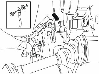
- Take a screw and toothed washer from the kit and tighten the ground cable in the front member.
- Take a tie strap from the kit and clamp the cable excess.
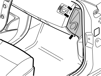
- Remove the panel from the right-hand end of the dashboard. Use a weatherstrip tool and carefully pry around the panel, so that the three clips on the inside release.
Примечание: Do not damage the dashboard.
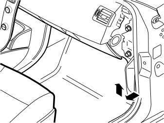
- Remove the sill trim panel from the right-hand front door. First pull off the front edge of the sill trim panel so that the clip there releases. Then continue backwards until the remaining clips on the underneath have released.
- Unhook the sill trim panel from the B-pillar panel.
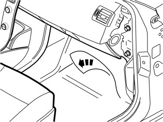
Applies to cars without a passenger compartment connector socket
- Push the floor carpet to one side to access the grommet in the cowl panel.
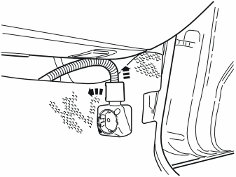
Applies to cars with a passenger compartment connector socket
- Remove the locking sleeve over the cable splice in the passenger compartment connector socket.
- Disconnect the cable from the passenger compartment connector socket.
- Remove the passenger compartment connector socket from its bracket.
- Push the floor carpet to one side to access the grommet in the cowl panel.
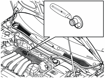
- Cut off the top of the small "rubber nipple" in the cowl panel's rubber grommet, on the right-hand side of the engine compartment. Use a knife.
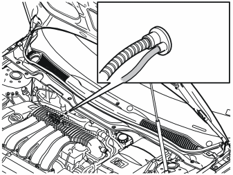
- Route the cable from the timer relay to the rubber grommet in the cowl panel.
- Insert the cable through the rubber grommet and into the passenger compartment.
- Insert all the cable excess into the passenger compartment.
- If the car is equipped with a passenger compartment connector socket; take a tie strap from the kit and clamp the cable at the cable to the passenger compartment connector socket.
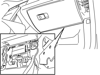
- Pull the cable from the rubber grommet in the cowl panel.
- Reinstall the wing liner for the side member and bumper cover.
- Reinstall the engine splash guard.
- Remount the wheel and tighten the lug bolts to 90 Nm (66 lbf.ft.).
Steps 26-50 apply to cars with 4-cylinder engines
- Turn the seven clips 90°.
- Detach the engine splashguard from the clips and place to one side.
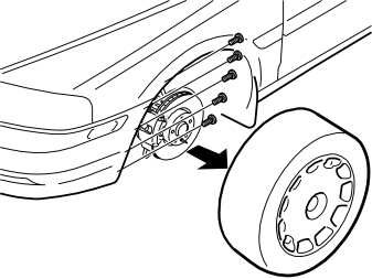
- Remove the left-hand front wheel.
- Remove the five screws holding the bumper cover at the left-hand wing liner.
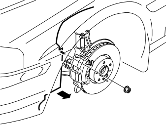
- Remove the nut holding the wing liner at the left-hand front member.
- Bend the front edge of the wing liner up over the brake caliper.
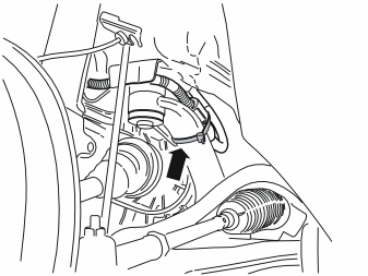
Only applies to cars with an engine block heater
- Cut off the tie strap above the locking sleeve.
- Detach the wiring from the front intake from its clamps, to facilitate installation of the timer relay. If necessary, also detach the cable from the engine block heater.
- Remove the locking sleeve over the cable splice and separate the cables.
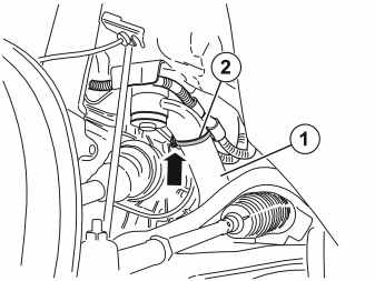
Applies to cars with an engine block heater and passenger compartment connector socket
- Detach the wiring from the front intake from its clamps, to facilitate installation of the timer relay.
- Detach the clamp that holds the junction connector at the stay.
- Remove the junction connector with cables from the clamp and stay.
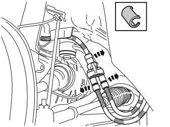
Applies to cars with an engine block heater and passenger compartment connector socket
- Remove the sleeves from above the splices on the cables for the front intake, engine block heater and passenger compartment connector socket.
- Remove the wiring from the junction connector.
- Remove the holder from the junction connector. The holder must be used for the timer relay but the junction connector must not be used again.
- Lubricate the O-rings on the cable from the front intake, timer relay and cable for passenger compartment connector socket (if applicable). Use low temperature grease (part no. 1161417-9).
Примечание: Do not get any grease on the surfaces of the connector.
- Take the bracket and rubber guard from the kit (or use the existing one). Press the rubber guard onto the bracket.
Only applies to cars with an engine block heater
- Take the screw, toothed washer and nut from the kit. Tighten the timer relay at the holder in the position illustrated. The holder must be longitudinally parallel with the timer relay.
- Press the cover (1) (part no. 346509, not included) onto the free socket in the timer relay.
Applies to cars with a passenger compartment connector socket
- Take the screw, toothed washer and nut from the kit. Tighten the timer relay at the holder in the position illustrated. The holder must be longitudinally parallel with the timer relay.
Illustration A
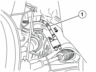
- Connect the front intake cable (1) to the timer relay. Press the cable splice together securely.
Illustration B
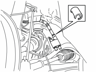
- Press in the existing locking sleeve over the cable splice.
Only applies to cars with an engine block heater
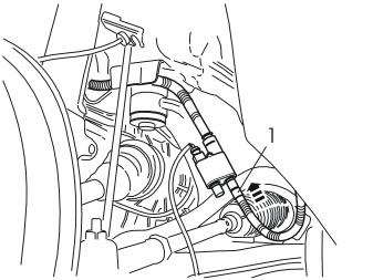
Illustration A
- Connect the cable (1) from the engine block heater to the timer relay. Press the splice together securely.
Illustration B
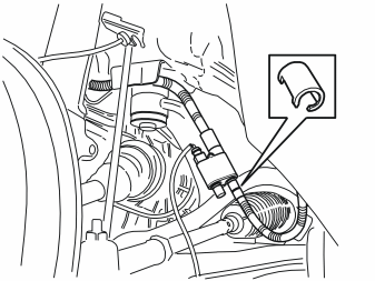
- Press a locking sleeve (from the kit) over the cable splice.
Applies to cars with an engine block heater and passenger compartment connector socket
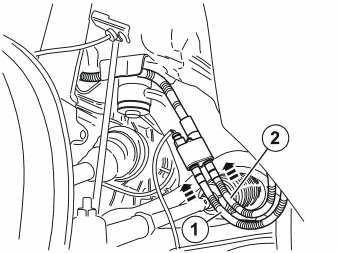
Illustration A
- Connect cable (1) from the passenger compartment connector socket and the cable (2) from the engine block heater to the timer relay.
- Firmly press the splices together.
Illustration B

- Press locking sleeves from the kit and press over the cable splices.
Illustration A
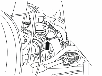
- Install the holder with the connected timer relay with the hose clamp. Ensure that the timer relay is centered on the stay and is secure, so that it does not drop down and become trapped by the anti-roll bar.
Illustration B
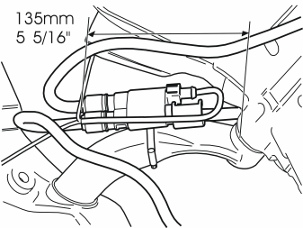
- Check that the same dimensions as in the image are used.
- If the cables for the front intake and engine block heater are disconnected, reinstall them in their clamps.
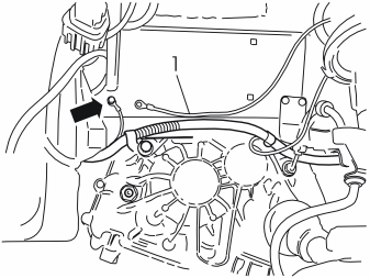
- Route the ground lead (1) from the timer relay to the ground terminal for the front intake.
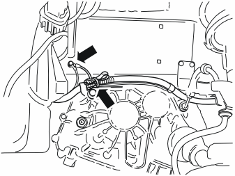
- Tighten the ground lead to the ground terminal.
- Clamp the ground lead at the existing clamps and clamp the cable excess using a tie strap from the kit.
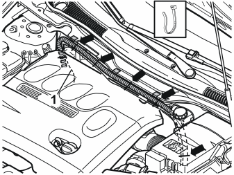
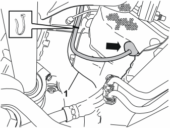
Illustrations A and B
- Route the cable from the timer relay (1) along the cable to the passenger compartment connector socket, up on the top side of the engine compartment's left-hand side and over to the right-hand side. Finish by pulling the cable down to the rubber grommet in the cowl panel.
- Take six tie straps from the kit and clamp the cable at the existing cable.
- Remove the panel from the right-hand end of the dashboard. Use a weatherstrip tool and carefully pry around the panel, so that the three clips on the inside release.
Примечание: Do not damage the dashboard.
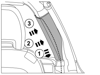
- Remove the sill trim panel from the right-hand front door. First pull off the front edge of the sill trim panel so that the clip there releases. Then continue backwards until the remaining clips on the underneath have released.
- Unhook the sill trim panel from the B-pillar panel.
Applies to cars without a passenger compartment connector socket
- Push the floor carpet to one side to access the grommet in the cowl panel.
Applies to cars with a passenger compartment connector socket
- Remove the locking sleeve over the cable splice in the passenger compartment connector socket.
- Disconnect the cable from the passenger compartment connector socket.
- Remove the passenger compartment connector socket from its bracket.
- Push the floor carpet to one side to access the grommet in the cowl panel.
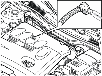
- Cut off the top of the small "rubber nipple" in the cowl panel's rubber grommet, on the right-hand side of the engine compartment. Use a knife.
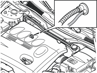
- Insert the cable through the rubber grommet and into the passenger compartment.
- Pull the cable from the rubber grommet in the cowl panel.
- Reinstall the wing liner for the side member and bumper cover.
- Reinstall the engine splash guard.
- Remount the wheel and tighten the lug bolts to 90 Nm (66 lbf.ft.).
Applies to all models
Installing the antenna
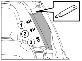
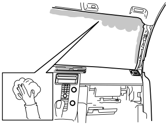
- Clean the marked surface on the inside of the windscreen using isopropanol P/N 1161721. Wipe dry.
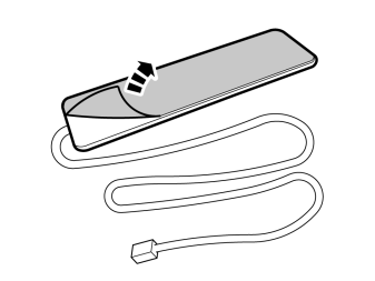
- Remove the protective backing tape from the antenna mounting tape.
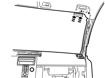
- Press the antenna into place as close to the front edge of the roof panel as possible. Route the cable just above the edge of the roof panel.
- Carefully bend down the front edge of the roof panel and use pieces of butyl tape to secure the cable at the panel.
Примечание: Do not damage the roof panel.
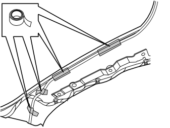
Внимание: Make sure that the routing of the antenna cable does not interfere with the function of the inflatable curtain.
Installing the receiver unit
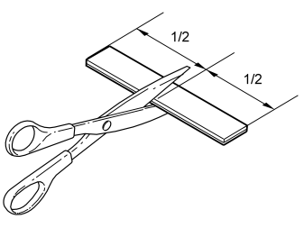
- Remove the Velcro from the kit and cut it in the centre.
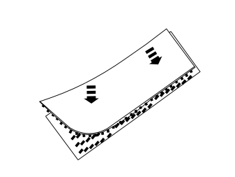
- Press the Velcro pieces together.
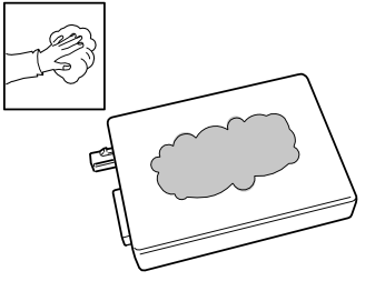
- Clean the flat surface of the receiver unit using isopropanol P/N 1161721. Wipe dry.
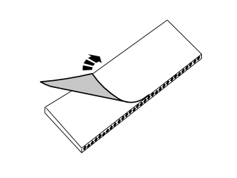
- Remove the protective backing tape from one of the Velcro pieces.
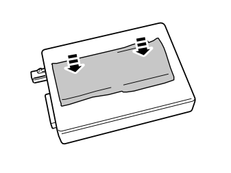
- Press the Velcro onto the receiver unit.
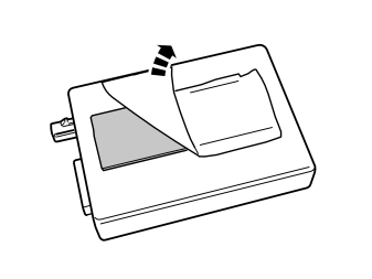
- Remove the protective backing tape from the other Velcro piece.
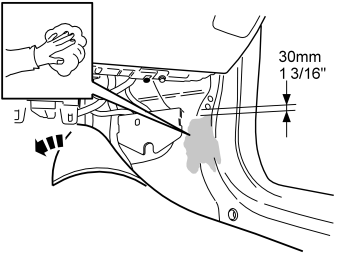
- Move the floor and insulating mat out of the way.
- Scrape away any sealing compound from the flat surface at the bottom edge of the A-post where the receiver unit for remote start will sit. The top edge of the receiver unit should be positioned 30 mm (1 3/16 ") from the bottom edge of the welded screw in the body.
- Clean the surface using isopropanol P/N 1161721. Wipe dry.
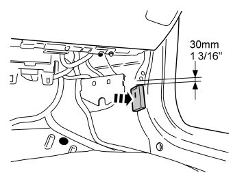
- Press the receiver unit securely onto the flat surface, 30 mm (1 3/16") from the lower edge of the welded screw in the body.

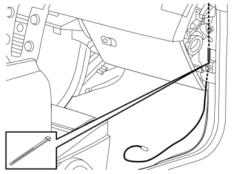
- Locate the 2-pin connector for the blower fan and disconnect the connector.
- Connect the cable from the kit.
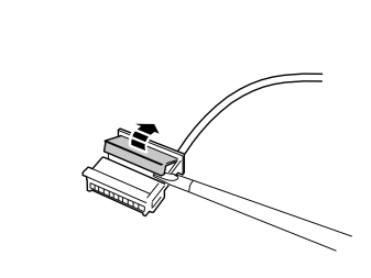
- Carefully loosen the secondary catch of the black 6-pin connector using a small screwdriver.
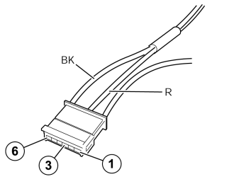
- Connect the red (R) cable from the timer relay to terminal 3, and the black (BK) cable to terminal 6 in the 6-pin connector.
- Press the secondary catch together on the connector.
Synchronizing the Transmitter - Receiver
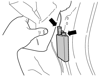
- Connect the battery's negative lead.
- Install batteries in the transmitter battery compartment.
- Connect the connector and antenna cable to the receiver unit.
- Within 5 seconds, press the "OFF" button on the transmitter until the LED goes out. Synchronization has been carried out.
- Press the receiver unit onto the Velcro on the body plate if it has loosened.
- Tape up any cable excess from the timer relay and place it next to the receiver unit under the insulation mat.
- Reinstall the insulation and floor carpet.
- Reinstall the removed panels and passenger compartment connector socket if applicable.
Обсуждение и оценка
0Пока нет комментариев. Будьте первым.