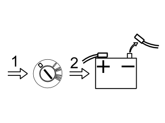
-
Turn the ignition switch to position 0.
-
Applies to cars with manual gearboxes: Remove the ignition key
- Disconnect the battery negative lead.
Примечание: Wait at least five minutes before disassembling the connectors or removing other electrical equipment.
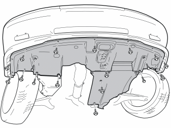
- Remove the front and rear engine splash guards.
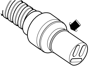
- Lubricate the O-ring on the rear right output on the junction connector using low temperature grease, P/N 1161427.
Примечание: Do not get any grease on the electrical switches.
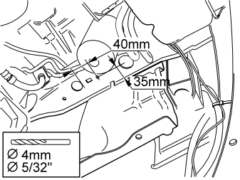
- Drill holes for the relay underneath the left-hand front member. Use a 4mm 5/32” drill bit as illustrated
- Treat the edges of the holes with a rust-proofing agent.
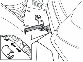
- Remove the locking sleeve over the cable terminal at the rear edge of the left-hand side member
- Pull off the front engine block heater socket cable from the cable for the engine block heater.
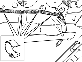
- Disconnect the cable from the front engine block heater socket from the clamps underneath the left-hand front member.
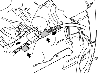
- Take the relay and screw from the kit. Lubricate the O-ring on the relay as carried out previously
- Tighten the relay underneath the side member in the drilled hole
- Take the extension cable from the kit. Lubricate the O-ring as before
- Press the cable into the rear socket in the relay. Press the smaller locking sleeve (from the kit) over the join
- Route the cable in the same direction as when it was removed
- Lubricate the cable to the front engine block heater socket as before
- Press the cable into the front socket of the relay. Press the larger locking sleeve (from the kit) over the join
- Secure the excess cable for the front engine block heater socket behind the bumper using two tie straps from the kit.
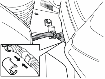
- Press the newly routed joint cable into the connector for the engine block heater
- Press securely into place. Take the existing locking sleeve and press over the joint
- Press the cable into the existing clamps.
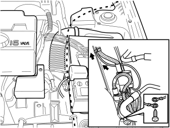
- Disconnect the ground lead for the front engine block heater socket underneath the front member. Tighten the ground lead for the relay and the front engine block heater socket ground lead
- If there is not a hole for the ground lead. Drill out a 4 mm 5/32” hole in the front end / lower edge of the underneath of the side member
- Treat the edges of the holes using a rust-proofing agent
- Route the other cable from the relay along the top edge of the left-hand side member underneath the battery holder, air cleaner (ACL) and fusebox to the accessory lead-in at the top edge of the cowl panel behind the left-hand spring strut.
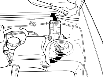
Applies to cars with cruise control
- Remove the two screws holding the cruise control. Move the vacuum pump to one side
- Remove the accessory lead-in
- Route the cable through accessory lead-in and the accessory hole in the passenger compartment
-
Примечание: > Do not route the thicker protective sheath on the cable through the accessory lead-in hole.
- Reinstall the accessory lead-in. Ensure that it is properly sealed
- Secure the cable in the engine compartment using the three tie straps from the kit. Ensure that the cable does not rub against the corner or other area
- Do not secure to the fuel lines, air conditioning (A/C) pipes or brake pipes.
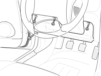
- Remove the panel under the dashboard on the driver's side
- Disconnect the cable for the courtesy lighting.
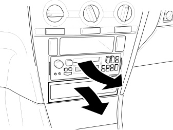
- Remove the radio
- Remove the connectors and the antenna cable
- Remove the centre console locker.
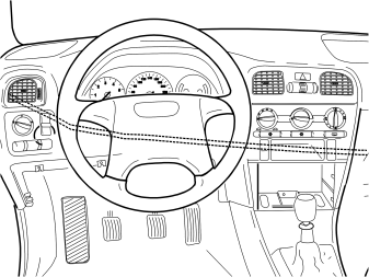
- Route the cable through the dashboard
- Clamp the cable. Use three tie straps from the kit
- Secure the cable so that it does not rub
- Open the glove compartment. Route the cable through the hole in the left-hand end.
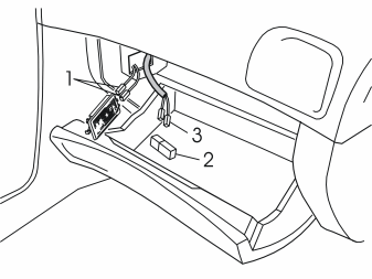
Applies to cars without a timer: type 4
- Remove the glove compartment lighting. Do not allow the cover behind to fall down behind the inside of the centre console
- Remove the cable harness with the green connector from the kit. Route the connector through the hole for the glove compartment lighting to the glove compartment
- Remove the two connectors (1) from the glove compartment lighting. Install the connectors in the white connector (2)
- Install the two other connectors (3) on the glove compartment lighting
-
Примечание: > Ensure that all connectors are connected colour to colour otherwise the timer will not function.
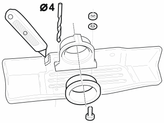
Applies to cars without a timer
- Install the spacer ring in the bracket for the timer
- Install the bracket for the timer in the storage compartment
- Mark the position for making holes. Drill two 4 mm 5/32”diameter holes
- Install and tighten the bracket for the timer
- Cut out an opening for the cable harness for the timer in the storage compartment.
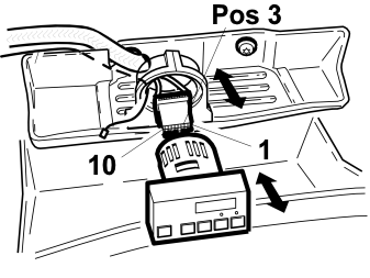
Applies to cars without a timer
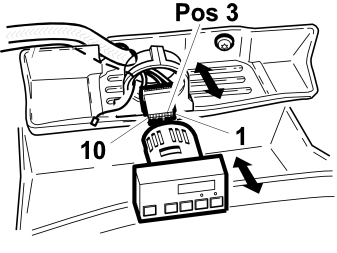
- Open the connector catch
- Connect the previously routed single cable to terminal 3 in the connector. Close the catch
- Connect the connector
- Press the timer into the bracket. Tighten the screw on the bracket.
Applies to cars with a timer and type 4 fuel heater
- Remove the timer from the bracket
- Remove the connector from the timer
- Open the connector catch
- Connect the previously routed single cable to terminal 3 in connector. Close the catch
- Press the timer into the bracket. Tighten the screw on the bracket.
- Connect the connectors to the radio. Reinstall the radio
- Where appropriate: reinstall the storage compartment under the radio
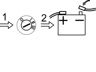
- Turn the ignition key to the ignition position (II)
- Reconnect the battery negative lead
- Program the anti-theft radio code.
Обсуждение и оценка
0Пока нет комментариев. Будьте первым.