Применимость
| Модель | Двигатель | Год |
|---|---|---|
| S80 (-06) | B6294S2 | 2003–2006 |
| S80 (-06) | B6294T | 2003–2006 |
| XC90 | B6294T | 2003–2006 |
| XC90 | B8444S | 2005–2008 |
Примечание: - Steps 1 - 46 apply to the XC90
- Steps 47 - 73 apply to the S80
Steps
- Turn the ignition switch to position 0.
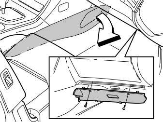
- Remove the right-hand side panel of the centre console by pulling it away starting at the front edge and then backwards until all clips have released.
- Remove the sound barrier on the right-hand side by first removing the two screws and then prizing it away at the top edge.
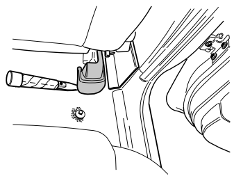
- Remove the cover panel on the right-hand rear mounting of the right-hand front seat. Prize it up slightly at the rear edge and then pull it back/upwards.
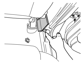
- Carefully prize away the cover panel over the joint between the door sills on the right-hand side, at the lower edge, using a weatherstrip tool. Remove the cover panel.
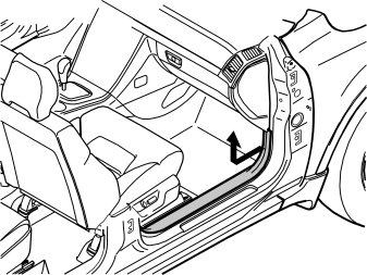
- Detach the right-hand front door's sill trim panel. Pull it away starting at the front edge until the clip there has released. Continue backwards until the remaining clips have released.
- Unhook it from the B-pillar panel and place it to one side.
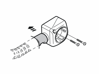
- Remove the screws to the passenger compartment connector socket and detach it from the bracket behind the carpet.
- Remove the locking sleeve and detach the cable from the passenger compartment connector socket.
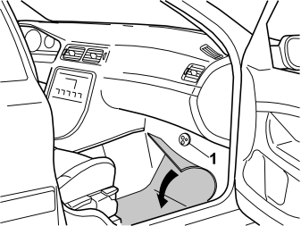
- Push the carpet to one side by the right-hand front seat.
- Press out the rubber grommet (1) under the insulation mat.
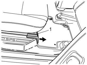
- Remove the panel in the right-hand front seat mounting, on the right-hand seat in the second row of seats. Push up the catch (1) on the top side and pull the panel forward.
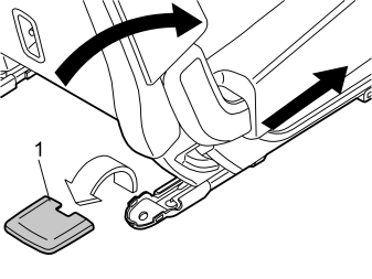
- Fold the backrest forward on the right-hand seat in the second row of seats as far as possible. Push the seat forward as far as possible. (On cars with two rows of seats the second row is fixed.)
- Remove the cover panel (1) for the right-hand rear seat mounting by prizing it away at the rear edge.
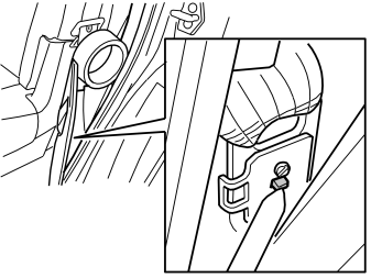
- Disconnect the top edge of the sill trim panel. Disconnect the seat belt from the end mounting by carefully pressing the locking tab with a weatherstrip tool, as illustrated, so that the seat belt releases from the end mounting.
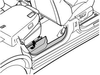
- Remove the sill trim panel by pulling it away completely at the rear edge until the clips there have released. Continue forwards until the remaining clips have released.
Applies to cars with two rows of seats
- On cars with two rows of seats, the seat cannot be pushed forward. To remove the sill trim panel, start by folding the backrest forward as the sill trim panel is pulled away at the rear edge. Following which, move the backrest back to raise the seat cushion, and so increase space for removing the sill trim panel. It is secured firmly, so ensure that the sill trim panel and adjoining components are not damaged during removal.
Illustration A
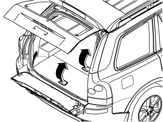
Applies to cars with two rows of seats
- Remove the two centre floor hatches by lifting them slightly and then pulling them away from their mountings at the front edge. If the rear centre floor hatch is equipped with grocery bag holder on the underside then the floor hatch is secured with a belt on each short side of the storage box. These must be detached.
- Remove the storage box.
Illustration B
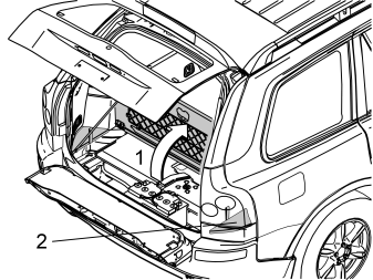
Applies to cars with three rows of seats and integrated carrier bag holder on the underside of the centre floor hatch
- Fold up the centre rear floor hatch (1).
- Detach the two straps on the underlying panel. Lift up the rear edge of the panel, fold the floor hatch back and lift out the floor hatch with the panel.
Applies to cars with three rows of seats without an integrated carrier bag holder
- Lift up the centre rear floor hatch at the rear edge and lift it out.
Applies to all models
- Remove the right-hand side floor hatch (2).
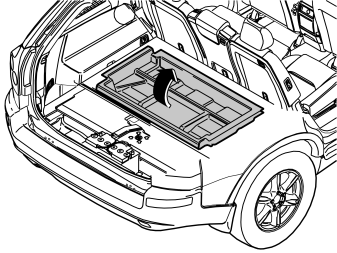
Applies to cars with two rows of seats
- Remove the front storage box.
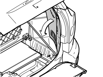
- Remove the folding side panel from the right-hand side of the cargo compartment.
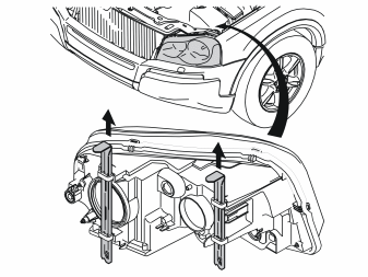
- Detach the left-hand headlamp by pulling up the two locking pins and then carefully pulling the headlamp away forwards.
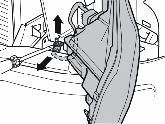
- Carefully prize up the catch on the connector for the headlamp using a screwdriver.
- Pull the catch up completely, detach the connector and place the headlamp to one side.
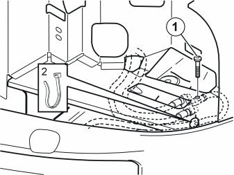
Applies to cars with V8 engine
- Remove the branch connector with the cables from the underside of the plate beneath the headlamp. Remove the screw, nut and washer (1) and tie strap (2), and pull the branch connector forward.
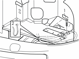
Applies to cars with 6-cylinder engine
- Remove the branch connector with the cables from the underside of the plate beneath the headlamp by removing the screw and the nut (1).
- Cut away the tie strap (2).
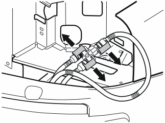
Applies to all models
- Remove the locking sleeves over the joints on the branch connector and pull the cables away from it.
- Place the branch connector to one side, it shall not be re-used.
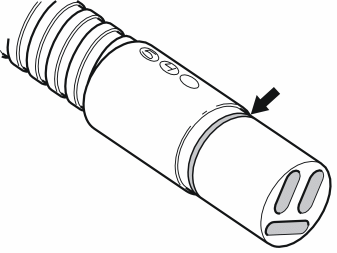
Applies to all models
- Take the relay with cable from the kit.
- Grease in the O-ring on the connector for the front socket and both connectors on the relay using low temperature grease (part no. 1161417-9).
Примечание: Do not get any grease on the surfaces of the connector.
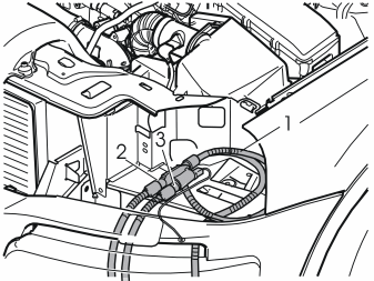
Applies to all models
- Connect the cable (1) from the front socket to the relay.
- Connect the cables to the engine block heater and passenger compartment connector socket to either of the sockets (2) or (3) on the relay and press them in firmly.
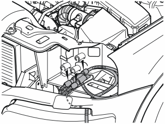
Applies to cars with V8 engine
- Take three locking sleeves from the kit and press them in over the cable joints.
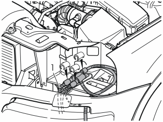
Applies to cars with 6-cylinder engine
- Take three locking sleeves from the kit and press them in over the cable joints.
- Take a tie strap (1) from the kit and clamp the electrical cable securely with the ground cable to one of the cables for the engine block heater/passenger compartment connector socket.
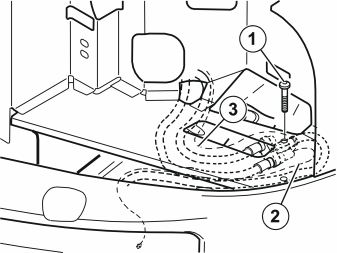
Applies to cars with V8 engine
- Take the relay with cables and fit it on the underside of the plate beneath the headlamp. Fit the relay with the side against the plate that allows the connector to be accessible.
- Take a screw, washer and nut (1) from the kit. Tighten the relay to the plate.
- Guide the relay's ground cable (2) down on the left-hand side of the side member.
- The long thin cable (3) from the relay is routed the same way as the cables for the heater and the passenger compartment connector socket, to enable later connection to the Accessory Electronic Module (AEM) in the cargo compartment.
- Clamp the ground cable with the cable to the front socket using a tie strap from the kit.
Applies to cars with 6-cylinder engine
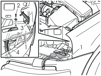
- Take the relay with cables and place it on the underside of the plate (1). Fit the relay with the side against the plate that allows the connector to be accessible.
- Take a screw, washer and nut (2) from the kit. Tighten the relay to the plate.
- Clamp the cable for the front socket at point (3) in the plastic eye for the bumper cover's mounting.
- Guide the thin cable with the ground cable from the relay down to the same location as the cables for the engine block heater/passenger compartment connector socket.
- Clamp all cables together at point (4) with a tie strap from the kit.
Steps 25 - 34 apply to the XC90 with V8 engine
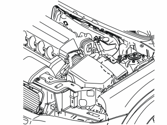
- Route the cable to the Accessory Electronic Module (AEM) the same way as the cable for the passenger compartment connector socket under the plate, beneath the left-hand headlamp. Route it backwards along the left-hand side of the air cleaner and between the air cleaner and fuse holder. Continue to route it backwards, under the ABS system and up between the cable duct and brake fluid reservoir.
- Check that the cable does not chafe against sharp edges or moving parts in the engine compartment.
- Route it along the cable for the passenger compartment connector socket over to the right-hand side of the car and down through the engine compartment.
- Clamp the cable securely the whole way with the cable for the passenger compartment connector socket using tie straps from the kit.
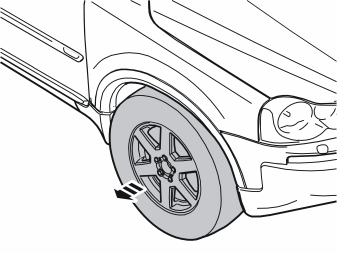
- Remove the right-hand front wheel for easier access for routing the cable to the Accessory Electronic Module (AEM).
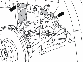
- Remove the two plastic nuts which hold the small protective panel in the right-hand wheel housing, and remove the panel.
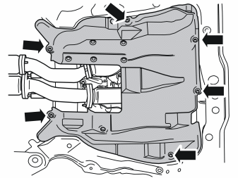
- Remove the six screws and the engine splash guard.
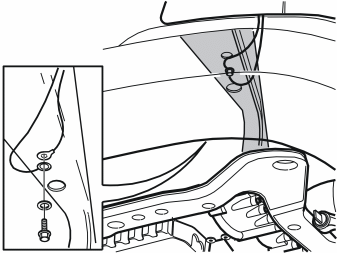
- Detach the existing ground cable for the front socket on the underside of the left-hand frame member.
- Route the ground cable on from the relay. Connect both ground cables to the existing ground terminal and tighten the ground screw firmly.
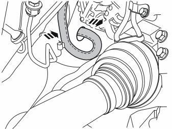
- Detach the cable for the passenger compartment connector socket from the clip in the edge of the plate, at the bending rubber hose for the water drainage.
- Route the rubber grommet with cable out to the passenger compartment connector socket from the passenger compartment.
- Remove the rubber grommet from the cable and place it to one side. There is a new rubber grommet on the routed cable.
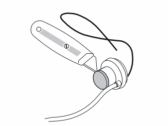
- Cut away the very top of the rubber grommet.
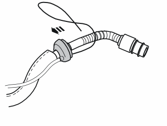
- Grease in the rubber grommet using low temperature grease part no. 1161417-9 in order to make it easier to install the rubber grommet in the hole in the cowl.
- Guide the cable into the rubber grommet.
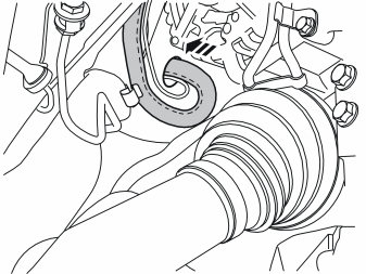
- Guide both cables into the hole in the cowl and press the rubber grommet into place in the hole, either by pulling it into place from inside the passenger compartment, or carefully pressing it into place with a long large screw driver/wide end of a short pry bar.
Примечание: These must not be sharp or they can damage the cables/rubber grommet
- Adapt the length of the cable from the rubber grommet, at the installed clip and out in the engine compartment.
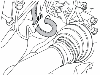
- Press the cables for the passenger compartment connector socket/Accessory Electronic Module (AEM) into the installed clip. Make sure that the cable with the radiation shield is firmly pressed into the clip and does not slide out.
Осторожно: Check that the cables are routed so that they do not come into contact with the alternator belt, or chafe against sharp edges in the engine compartment.
- Clamp the cable for the Accessory Electronic Module (AEM) with the thick cable using tie straps from the kit.
- Reinstall the small protective panel in the wheel housing.
- Reinstall the engine splash guard and torque tighten the screws to 25 Nm (18.5 lbf.ft.).
- Remount the wheel and tighten the bolts to 140 Nm (103 lbf.ft.).
- Connect and reinstall the left-hand headlamp.
Steps 35 - 38 apply to the XC90 with 6-cylinders
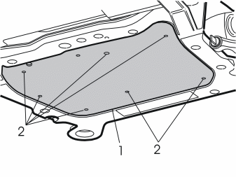
- Remove the screws (2) and the engine splash guard (1).
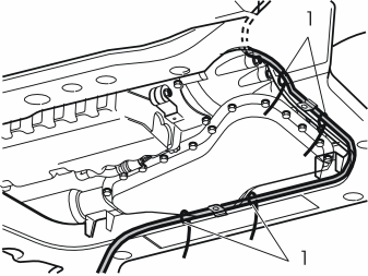
- Route the electrical cables down from the relay.
- Take four tie straps from the kit and clamp the thin electrical cable (not the ground cable) to the cable for the passenger compartment connector socket.
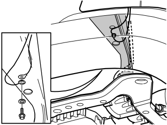
- Detach the existing ground cable for the front socket on the underside of the left-hand frame member.
- Route the ground cable on to the relay. Connect both ground cables to the existing ground terminal.
Illustration A
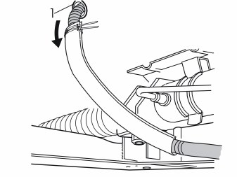
- Pull the cable with rubber grommet (1) away from the passenger compartment connector socket.
- Pull the whole cable out from the hole in the cowl wall. Remove the rubber grommet from the cable. There is a new one on the routed electrical cable.
Illustration B
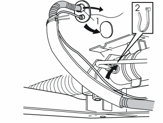
- Cut away the top of the new rubber grommet (1).
- Guide the passenger compartment connector socket's cable in through the new rubber grommet.
- Grease in the rubber grommet with low temperature grease (part no. 1161417-9) on the side turned into the passenger compartment.
- Adapt the cables up to the grommet. Guide the cables into the hole in the cowl wall.
- Carefully pull the rubber grommet into position from inside the passenger compartment by pulling in the cable for the passenger compartment connector socket.
- Clamp in the electrical cable with the servo pipe using a tie strap (2) from the kit.
Applies to all models
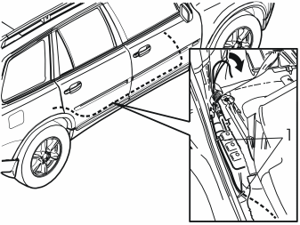
- Route the cables for the passenger compartment connector socket and the Accessory Electronic Module (AEM).
- Guide the Accessory Electronic Module (AEM) cable harness down between the carpet and the door sill towards the floor as far as possible. Route it along the right-hand side of the car, on to the door opening for the right-hand rear door.
- Route the cable by the right-hand seat mounting on the right-hand seat in the second row of seats.
- Pull away the mat from the front edge of the right-hand side panel in the cargo compartment.
- Route the cable on the right-hand side of the air duct towards the front edge of the rear wheel housing. Clamp it in at the air duct using two tie straps (1) from the kit.
- Route the cable on the rear of the air duct and out at the front edge of the wheel housing.
Applies to cars with three rows of seats, Illustration A
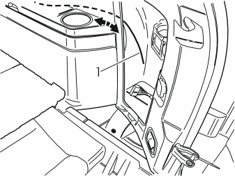
- Guide in a wire (1) at the rear edge of the right-hand side panel and along its inside, above the load securing eyelet brackets, and on to the front edge of the side panel.
Illustration B
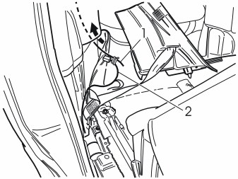
- Tape the cable harness (2) to the wire and route it on from the rear edge of the side panel.
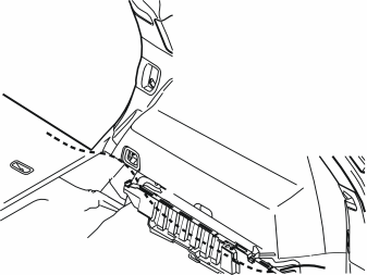
Applies to cars with two rows of seats
- Route the cable on the left-hand side of the seat belt's mounting at the front edge of the wheel housing, inside the carpet at the front edge of the side panel, between the side panel and the rear cargo floor support, to the Accessory Electronic Module (AEM).
Applies to all models
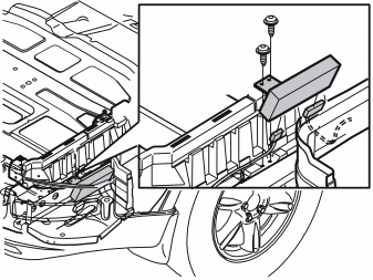
- Remove the two screws in the Accessory Electronic Module (AEM) bracket and lift up the whole unit. Cut away the tie straps as necessary.
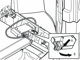
- Disconnect the large connector on the Accessory Electronic Module (AEM). First press in the catch (A). Pull the black locking handle (B) in the direction of the arrow until a click is heard.
- Disconnect the connector from the accessory electronic module.
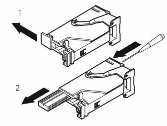
- Remove the black catch holding the black connector socket in place in the connector by pulling in the direction of the arrow.
- Remove the black connector socket. Insert a pointed object in the hole on the other end of the connector. Press the connector socket out.
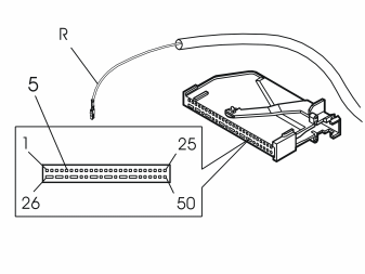
- Connect the pre-routed cable to terminal 5 of the Accessory Electronic Module (AEM) connector.
Примечание: The numerical markings can be found on the top and bottom of the connector. However, the markings are extremely small so be careful when installing the cable.
- Reinstall the connector in the socket and refit it in the Accessory Electronic Module (AEM).
- Reinstall the Accessory Electronic Module (AEM) with bracket.
- Reinstall the storage box and floor hatches.
- Reinstall the folding panel on the rear right-hand side.
- Reinstall the sill trim panel in the right-hand rear door.
- Press the seat belt into the end mounting.
Примечание: A clear click is heard when the seat belt has locked correctly with the end mounting.
Примечание: Also check that the seat belt has locked correctly with the end mounting by looking at the reverse of the end mounting.
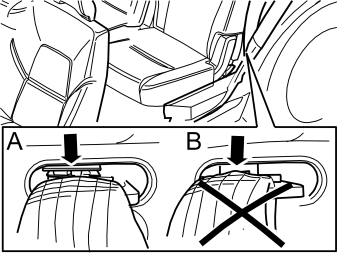
The position of the lock tab against the end mounting with the seat belt fully inserted must be:
A= Correct locked position. B= If the lock tab does not lock correctly against the end mounting, see A, replace the end mounting with a new one.
Примечание: Check that the seat belt is secure by jerking it hard in an upwards direction.
- Fold the carpet back on the front right-hand side, connect the cable for the passenger compartment connector socket and reinstall it.
- Reinstall the front sill trim panel.
- Reinstall the panel in the lower edge of the B-pillar panel.
- Reinstall the panels over the seat mountings.
- Reinstall the sound barrier and the centre console's side panel on the right-hand side.
- Program the software in accordance with the service information.
Steps
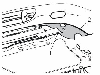
- Raise the car.
- Remove the screw (1) in the left air baffle (2) for the front brake.
- Remove the left-hand air baffle by pulling it backwards.
- Remove the right-hand air baffle in the same way.
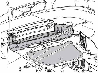
- Remove the screws (1).
- Remove the air baffle by pressing in the catches (2) and pulling it down/backwards.
- Remove the screws (3) and remove the splash guard.
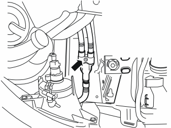
- Remove the screw and the branch connector on the underside of the side member.
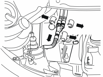
- Remove the locking sleeves over the joints on the branch connector and pull the connectors away from the branch connector.
- Place the branch connector to one side. It shall not be re-used.
- Grease in the O-rings on the relay and front socket connectors using low temperature grease (part no. 1161417-9).
Примечание: Do not get any grease on the surfaces of the connector.
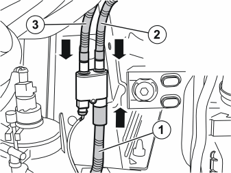
- Take the relay from the kit and connect the front socket cable (1), the engine block heater cable (2) and the passenger compartment connector socket cable (3). Press the joints together firmly.
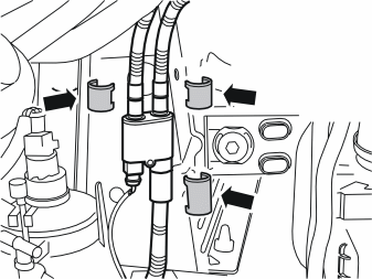
- Press in the locking sleeves from the kit over the joints.
Примечание: The large locking sleeve must be pressed over the connector on the cable from the front engine block heater socket.
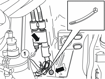
- Tighten the relay on the underside of the side member with a screw from the kit in the same hole where the branch connector was fitted.
- Connect the relay's ground cable to the existing ground terminal in the front end of the side member. Tighten it firmly.
- Clamp the excess ground cable to the front socket cable. Use a tie strap (1) from the kit.
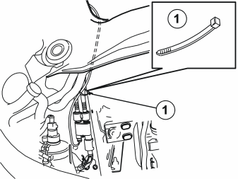
- Route the relay's solid core wire on the top of the subframe's right-hand front corner together with the other cables to the engine block heater/passenger compartment socket.
- Clamp the relay's solid core wire to the existing cables. Use a tie strap (1) from the kit.
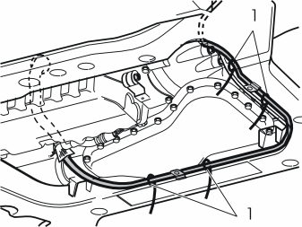
- Route the solid core wire along the cable for the passenger compartment connector socket and clamp it there. Use tie straps (1) from the kit.
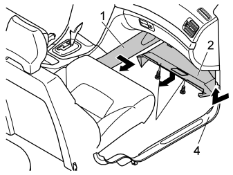
- Remove the centre console's right-hand side panel (1) by turning the clip in the rear edge 45°. Pull the panel out at the rear edge and then straight back.
- Remove the sound barrier (2) by first removing the three screws (3). Prize it away from the three clips on the rear and pull the panel backwards.
- Remove the panel (4) in the right-hand front door sill by pulling it away backwards at its top and front edges. Following which, pull the panel up so that all the clips detach.
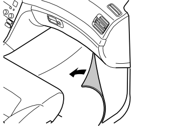
- Remove the locking sleeve over the joint between the cable and the passenger compartment connector socket and pull the cable away.
- Remove the passenger compartment connector socket
- Fold aside the carpet at the right-hand front seat to access the grommet in the engine compartment. It is slightly to the left in the lower edge of the sound barrier.
- Route the rubber grommet with cable out to the engine compartment.
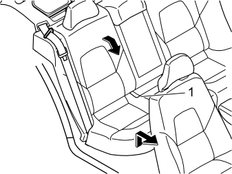
- Remove the seat cushion (1) by pulling up its front edge, pulling it forwards and then lifting it out.
- Fold the right-hand rear backrest forward.
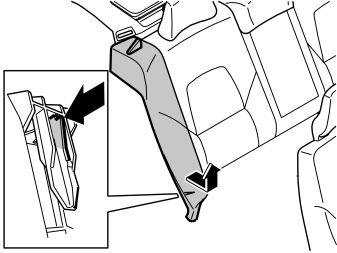
- Remove the right-hand side bolster by putting a hand in on the side of the lower section of the side bolster.
- Release the catches. At the same time lift the side cushion.
- Place the cushion to one side.
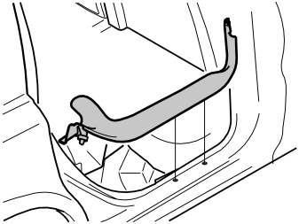
- Remove the panel in the right-hand rear door sill by first pulling it up at its rear edge so that the clips release. Following which, continue to pull it up forwards so that the remaining two clips detach.
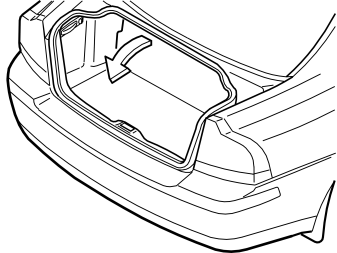
- Remove the carpet from the luggage compartment.
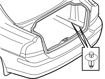
- Press in the centre of the clips in the lower edge of the right-hand side of the folding panel until they click.
- Remove the clips.
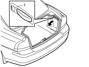
- Turn the handle (1) on the right-hand side through 90°.
- Fold the side panel inwards and lift it out.
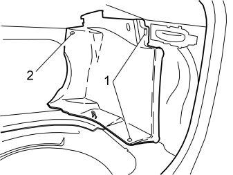
Remove:
- the clips (1) in the right front side panel in the cargo compartment.
- the clips (2) at the top of the front edge on the side panel for the rear folding backrest.
- the panel.
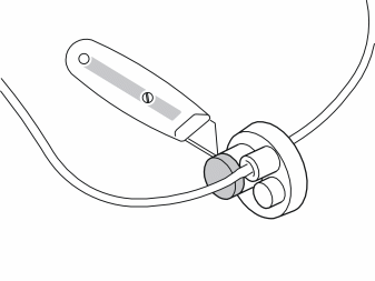
-
Remove the rubber grommet on the cable for the passenger compartment connector socket.
-
Cut away the top of the large rubber stud on the rubber grommet of the newly routed cable harness.
- Apply low temperature grease (part no. 1161417-9) on the rubber grommet to make it easier to install the cable through to the passenger compartment connector socket.
- Guide the passenger compartment connector socket's cable in through the rubber grommet.
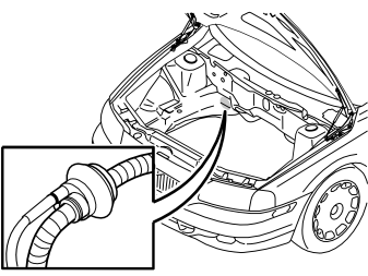
- Guide the passenger compartment connector socket's cable and solid core wire into the passenger compartment.
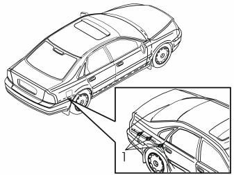
- Route both cables on to the front edge of the sill on the right-hand front door.
- Continue to route the solid core wire along the right-hand side of the car inside the floor carpets and insulation mats to the location for the Accessory Electronic Module (AEM) on the right-hand side in the cargo compartment on the rear of the rear wheel housing. Take care to position the solid core wire so that it is not at risk from chafing or being trapped.
- Clamp it in at the cable ducts in the cargo compartment. Use three tie straps (1) from the kit.
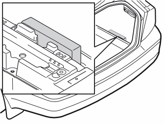
- Pull up the control module from its bracket.
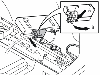
- Detach the large connector from the control module by pressing in the catch (A) and pull the locking handle (B) in the direction of the arrow until a click is heard.
- Pull the connector out from the control module.
- Remove the catch holding the connector socket in place in the connector by pulling in the direction of the arrow.
- Remove the connector socket. Insert a pointed object in the hole on the other end of the connector. Press the connector socket out.
- Connect the pre-routed cable to terminal 5 of the Accessory Electronic Module (AEM) connector.
Примечание: Number markings can be found on the top and bottom of the switch. The markings are very small. Ensure accuracy when installing the cable.
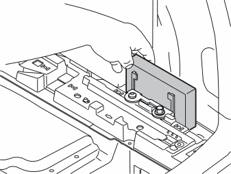
- Reinstall the connector socket in the connector. Lock it into place using the catch.
- Press the connector into the control module and lock with the locking handle.
- Press the control module into its bracket.
- Reinstall the panels in the cargo compartment.
- Reinstall the cargo compartment carpet.
- Reinstall the sill trim panel in the rear door.
- Reinstall the side cushion.
- Reinstall the seat cushion.
- Fold the backrest back into place.
- Fold back the carpet at the front seat.
- Connect the cable to the passenger compartment connector socket and secure it.
- Reinstall the sill trim panel in the front door.
- Reinstall the sound barrier and the centre console's side panel.
- Reinstall the centre air baffle.
- Reinstall the engine splash guard and torque tighten the screws to 24 Nm (18 lbf.ft.).
- Reinstall the air baffles at the sides if the car is so equipped.
- Program the software in accordance with the service information in VIDA.