Применимость
| Модель | Двигатель | Год |
|---|---|---|
| XC90 | — | 2003–2008 |
Осторожно: Take care when cutting away the headlining in step 10. There is a risk of cutting off the cable harnesses and hose for the washer fluid.
Only use a sharp utility knife or similar for cutting into the headlining. Replace the blade when it becomes blunt.
Внимание: Protect skin, eyes and respiratory tracts using appropriate protective equipment so that they are not exposed to loose roof material.
Preparations
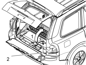
Applies to two-wheel drive cars with two rows of seats
- Remove the rear floor hatch (1) by folding it back slightly and pulling it backwards out of its mountings.
Applies to other cars with two rows of seats
- Fold up the rear floor hatch (1).
- If the floor hatch has a carrier bag holder on the lower side, it is secured in the car by two straps either side of the bottom of the carrier bag holder. Pull both straps away from the protruding mountings.
- Remove the storage box from under the floor hatch. Lift out the storage box.
Applies to cars with three rows of seats and integrated carrier bag holder on the underside of the floor hatch
- Fold up the rear floor hatch (1).
- Disconnect the two straps on either side of the bottom of the carrier bag holder from the protruding mountings. Lift up the rear edge of the carrier bag holder, fold the floor hatch back towards the bottom and lift out the carrier bag holder.
Applies to cars with three rows of seats without an integrated carrier bag holder
- Fold up the rear floor hatch (1) at the rear edge and lift it out.
Applies to all models
- Remove the right-hand side floor hatch (2). Lift the floor hatch straight up.
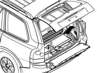
- Remove the lower side panel on the right-hand side.
Illustration A
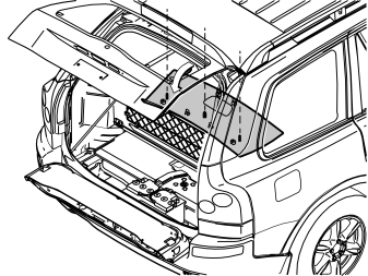
- Remove the covers from the rear headlining panel. Unscrew the screws from inside the panels.
- Carefully pry off the headlining panel at the rear edge using a plastic weatherstrip tool.
- Grip the rear edge of the headlining panel. Pull the headlining panel down until all the clips on the inside release.
Applies to cars with three rows of seats
- Disconnect the connector for the rear roof lighting. Pull the panel backwards.
Illustration B
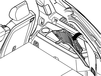
- Carefully pull off the top edge of the right-hand D-post panel. Continue down until the three clips have released.
- For cars with D-post loudspeakers: disconnect the connectors for this loudspeaker.
- Remove the right-hand D-post panel by pulling upwards slightly and unhooking it from the side panel.
Примечание: Cars with Vehicle Identification Number CH -32000: Follow the instructions in the installation instructions for the adapter wiring.
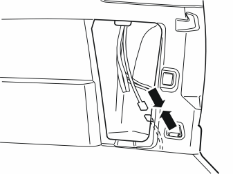
- Take the RSE system cable harness from the kit. Connect the 5-pin connector to the connector beside the right-hand tail lamp.
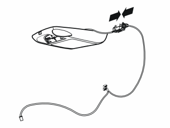
- Take the LCD display from the kit. Connect the 16-pin connector on the cable harness to the LCD display.
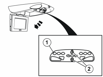
- Turn the ignition key to position I.
- Hold the display unit so that the display can be folded out without hindrance.
- Fold out the display by pressing the ON button (1). Adjust the position of the display using the two buttons (2) in the middle of the control panel to achieve an opening angle of approximately 90 degrees.
- Interrupt the power supply by disconnecting the 16-pin connector from the display.
- Disconnect the 5-pin connector from the car.
- Turn the ignition key to position 0.
Rear hole-punching (for DVD unit)
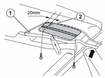
- Temporarily borrow two 4.8x13 mm screws from the installation kit for the DVD player.
- Release the roof clip (1) located between the C-posts. Turn the clip 90° and work it out.
- Install the hole template. Press the hole template into place with the clip (1) and guide it up against the edge of the C-post (arrow).
- Secure the hole template at two points using the screws to ensure it is securely mounted against the headlining.
- Cut out the headlining along the inner contours of the hole template. Use a utility knife or similar. If the car has a mass movement sensor (MMS): Cut approximately 20 mm further in first (see alternative dotted line (2)). This is because there is wiring in the headlining. The wiring may need to be moved. Using a weatherstrip tool, pry the wiring away from the adhesive on the headlining. Do not damage the wiring when cutting the hole.
Примечание: Use a sharp knife. Applies to all cutting of the headlining.
- Remove the template and cut away the flanges on which the screws recently rested.
- Reinstall the roof clip (1).
Applies to cars with sun roof (point
Front hole-punching (for LCD display)
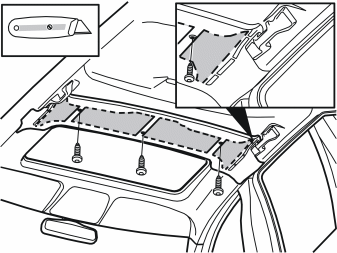
- Ensure that the headlining for the sun roof is pulled forward.
- Temporarily borrow three 4.8x13 mm screws from the installation kit for the DVD player.
- Install the hole template in position. Guide it up along the grab handles and secure it to the roof using the screws.
- Cut through the headlining according the dotted lines in the four large openings in the template. Only cut through the fabric. Alternatively use a pen to mark in the four narrow grooves as far out as possible on each side. The headlining can be cut through here once the cable harnesses and hoses found in this area have been moved.
- Remove the template and cut through the headlining at the parts between the four large openings, in order to remove a large portion of the headlining.
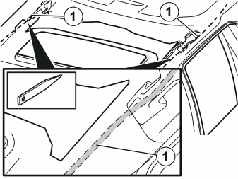
- Remove the wiring (1) that is bonded to the inside of the headlining on the right and left-hand sides of the car. Use a weatherstrip tool to pry the wiring away from the bonding.
- Press the wiring out towards the sides of the car.
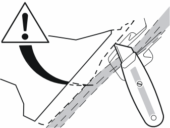
Осторожно: Take care when cutting away the side pieces of the headlining. There is a risk of cutting off the cable harnesses and the hose for the washer fluid.
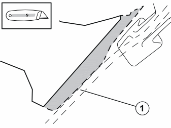
- Use a suitable section of plastic and apply it as protection for the cables when cutting out at the sides of the car.Press in the cables (1) which are routed to the side. Protect them with the section of plastic and carefully cut away the last side piece which was marked with a pen earlier.
Примечание: Be careful with the electrical cables and the hose for washer fluid. Constantly check that they are not damaged.
Cable routing
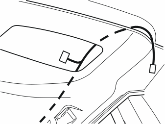
- Take out the cable harness for the RSE system.
- Thread a suitable cable or wire between the holes in the headlining. Secure the end of the cable harness with the 5-pin connector to the wire which comes out from the hole for the DVD player.
- Route the end of the cable harness through to the second hole and remove it from the wire.
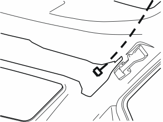
- Thread a suitable cable or wire between the hole for the DVD player and the hole for the LCD screen's roof member.
- Secure the cable harness' 16-pin connector to the wire. Route the cable so that the connector comes out at the LCD screen's roof member. Detach the cable from the wire.
Installing roof member brackets
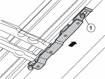
Примечание: Do not disturb the spacers located between the sun roof member and the roof. It can be difficult to locate the spacers in position again.
- Unscrew the rear screw (1) in the sunroof's right-hand mounting rail. Use a pair of pliers to pull it straight down from the hole. It is held in position by a plastic washer so significant force is required.Do this on the right and left-hand sides, and place the screws to one side.
- Take the bracket, the M6x40 mm screw and the washer from the kit (kit illustration A). Install the bracket loosely, with the screw through the longer hole, and slide it backwards.
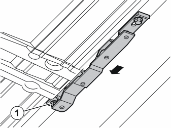
- Slacken off the front screw (1) in the same rail. Slide the bracket forwards. Secure the bracket using one M6x30 mm screw and washer from the kit.
-
Tighten both screws. Tighten to 10 Nm (7.5 lbf. ft.).
-
Install the roof member bracket in the same way on the other side.
Installing the roof member
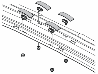
- Take the roof member, four plastic threaded plates and four spacer clips from the kit.
- Install the threaded plates as illustrated.
- Install the spacer clips from the other side, so that they are properly secured to the threaded plates.
- Take two 140x50 mm pieces of tape from the kit. Cut to make four 70x50 mm pieces.
- Tape the threaded plates in position as illustrated.
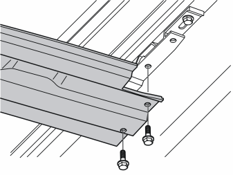
- Thread the roof member a little way under the rear edge of the headlining. It should be possible to slide the roof member back in under the front edge. Work the roof member into place by the screw holes. Ensure that the cut-outs in the ends of the member are facing backwards.
- Take the two M6x14 mm screws from the kit. Screw the roof member into the recently installed brackets.
- Tighten the screws. Tighten to 10 Nm (7.5 lbf. ft.).
Installing the LCD display
Illustration A
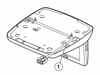
- Cut off the tie strap (1).
Illustration B
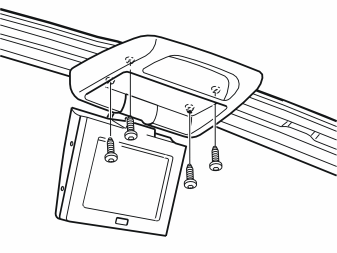
- Position the LCD display against the centre of the roof member. Guide the holes in the panel for the LCD display onto the spacer clips for the threaded plates.
- Take the 4x20 mm screws from the kit. Loosely screw the LCD display into place. Approximately 7 mm is required between the display and the member in order to install the panel.
Illustration C
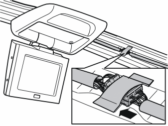
- Connect the cable harness connector to the LCD display connector.
- Take the foam tape from the kit. Wrap the foam tape around the connector.
- The connector must be positioned in the member recess. Fix the connector using the 140x50 mm tape from the kit.
Installing the panels
Illustration A
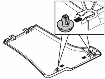
- Take the panels for the roof member and the four plastic clips from the kit.
- Install the plastic clips in the clip pockets in the panels.
Illustration B
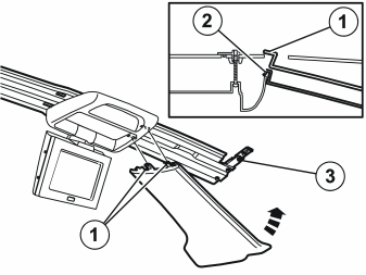
- Insert the panel hooks in the roof member cut-outs (1) by the LCD display and between the display and the member (2). Bend the panel down in the middle. Slide the panel up over the grab handle. Press the plastic clips for the panel into the holes (3) in the brackets.
Примечание: Do not damage the grab handle when sliding the headlining panel into position.
- Screw the display unit into place.
- Continue with point 27.
Point
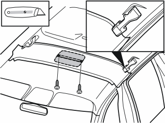
- Temporarily borrow two 4.8x13 mm screws from the installation kit for the DVD player.
- Install the hole template in position. Guide it up along the grab handles and secure it to the roof using the screws.
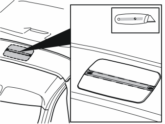
- Cut out the headlining along the inner contours of the hole template. Use a utility knife or similar.
Примечание: Use a sharp knife. This applies to all cutting of the headlining.
Cable routing
- Route the wiring according to points 11 and 12.
Installing roof member brackets
Illustration A
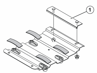
Подсказка: Use suitable blocks or similar to make space between roof and headlining.
- Take the bracket, the narrow bracket clamp and the four threaded plates from the kit (kit illustration B).
- Install the threaded plates as illustrated.
- Install the spacer clips from the other side, so that they are properly secured to the threaded plates.
- Take two 140x50 mm pieces of tape from the kit. Cut to make four 70x50 mm pieces.
- Tape the threaded plates in position as illustrated.
- Take two nuts from the kit. Install the narrow bracket clamp (1) on the angled side of the bracket. Screw the clamp into place using the nuts.
- Slide the narrow bracket clamp so that it is as far out as possible in the slit holes. Rest the clamp on the angled surface. Tighten the nuts by hand.
Illustration B
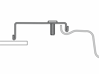
- Hold the wide bracket clamp with the less folded edge forwards. Thread the clamp into the hole in the roof, on the rear side of the roof member. Work the bracket clamp into place so that it rests above the edges of the roof member and the headlining with the screws facing downwards.
Примечание: The less folded edge must be positioned above the edge of the roof member.
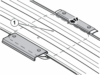
- Insert the bracket into the cut out hole with the narrow bracket clamp at the front, facing the knob.
- Unscrew the nuts holding the narrow bracket clamp. Slide the clamp over the edge of the roof member so that it hooks into place. Tighten the nuts so that the bracket remains attached.
- Lift up the rear end of the bracket. Align the screws for the suspended wide bracket clamp in the holes in the bracket. Screw in two nuts from the kit. Finger tighten.
- Check that both clamps on the bracket are correctly positioned around the roof member.
- Adjust the position of the bracket so that its hole is aligned with the hole in the roof member (1).
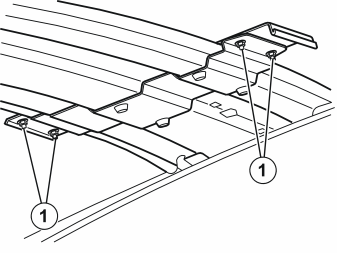
- Tighten the four screws (1) for the catches so that the bracket is securely mounted. Work the bracket and further tighten if there is any play.
Installing the LCD display
Примечание: Two people are required to connect and screw the LCD display into place.
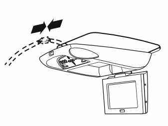
- Pull the cable harness for the LCD display out of the hole to facilitate connector connection.
- Hold up the display against the hole cut out in the roof. Connect the 16-pin connector on the cable harness to the connector from the LCD display.
- Take the foam tape from the kit. Wrap the foam tape around the cable harness.
- Lift the display towards the roof at the same time as pressing in the excess cable.
- Position the LCD display against the centre of the bracket. Guide the holes in the panel for the LCD display onto the spacer clips for the threaded plates (see illustration 17 B).
- Take the 4x20 mm screws from the kit. Screw the display into place.
Applies to all models
Installing the DVD player in the bracket
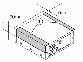
- Take the two 140x50 mm pieces of tape from the kit.
- Install the pieces of tape (1) on the sides of the DVD player.
The tape will ensure that the DVD player is insulated from the bracket.
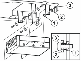
- Install the 4 collared washers (1) from the inside in the bracket. Use butyl tape to hold them in place if necessary.
- Install the DVD player using the plastic washers (2) and the M4x8 mm screws (3).
Примечание: Longer screws can damage the DVD player and must therefore not be used.
The plastic washers on the inside and outside are there to separate the DVD player from the bracket.
Installing the DVD bracket together with DVD
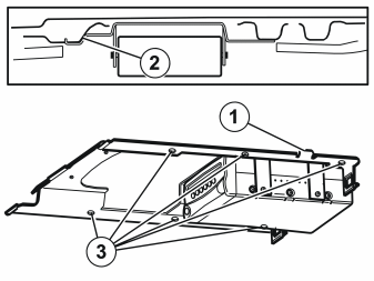
- Take the DVD bracket together with the DVD player.
- Install it in the hole. Insert the locating pin (1) and press it backwards, towards the cargo compartment, so that the bracket is in contact with the mating surfaces (2).
- Take six 4.8x13 mm screws from the kit.
- Drill a Ø3.8 mm diameter hole. Tighten a screw in one of the holes (3) in the bracket.
- Drill another Ø3.8 mm diameter hole. Tighten a screw on the opposite side.
- Drill and screw the remaining holes.
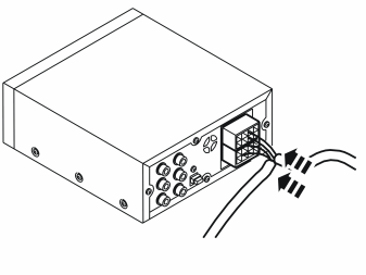
- Plug the connectors into the corresponding connector sockets in the DVD player.
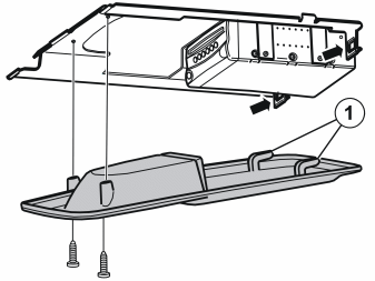
- To make installation of the DVD player cover easier: Take two 4.8x13 mm screws from the kit. Create threads in the bracket by screwing in and unscrewing the screws.
- Take the cover for the DVD player from the kit. Slide the cover upwards and forwards until the two hooks (1) catch in the bracket cut-outs and the DVD player front is positioned in the opening. Ensure that the cover does not catch in the headlining.
Примечание: The cover must not scratch the front of the DVD player.
- Screw in the cover by hand using the two 4.8x13 mm screws.
Connecting the cable harness
Illustration A
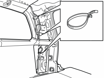
- Route the cable with the five-pin connector down along the D-post to the existing connector by the right-hand tail lamp.
- Secure the cable to the existing cable harness as illustrated. Use four tie straps (1) from the kit.
Illustration B
- Connect the 5-pin connector to the existing connector beside the right-hand tail lamp.
Installing decals
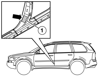
- Take the yellow decal from the kit.
- Clean the area (1) where the decal will be located. Use a mixture of 30% windscreen washer fluid and 70% water. Wipe dry.
- Remove the backing paper from the adhesive side of the decal. Secure the decal as illustrated.
- Press the decal into place properly.
Test the system
- Follow the instructions in the manual to test the system.
- Remove the transport protection disc from inside the DVD player.
Reinstall:
- the side panels in the cargo compartment
- the headlining panel in the cargo compartment
- the floor hatch in the cargo compartment.
Vacuum clean and clean away roof material and other waste from the car.