Применимость
| Модель | Двигатель | Год |
|---|---|---|
| S60 (-09) | D5244T | 2001, 2002 |
| S60 (-09) | D5244T2 | 2002 |
| S80 (-06) | D5244T | 2001, 2002 |
| S80 (-06) | D5244T2 | 2002 |
| V70 (00-08) | D5244T | 2001, 2002 |
| V70 (00-08) | D5244T2 | 2002 |
Preparations, interior (applies to the V70 and V70XC)
Applies to the V70 XC
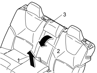
- Fold the centre seat cushion (1) forwards. Fold the centre backrest (2) forwards by pulling the lever (3) towards you.
Applies to the V70 XC
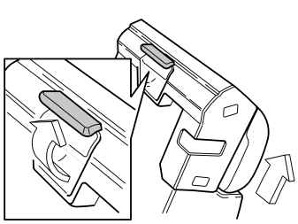
- Remove the centre backrest. First pull the handle at the top of the reverse of the backrest. Then pull the backrest upwards.
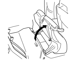
- Fold the right-hand rear seat cushion forward.
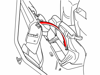
- Fold the right-hand rear backrest forward.
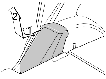
- Remove the right-hand side cushion. First pull the top edge (1) towards you. Then lift the side cushion upwards (2).
Preparations, interior (applies to the S60 / S80)
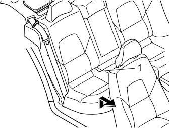
- Remove the rear seat cushion (1) by pulling it up at the front and then forwards.
Applies to the S80 only
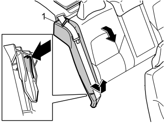
- Fold the right rear backrest forward
- Remove the seat belt from the guide (1)
- Insert a hand down the side of the lower section of the right side cushion
- Release the catches. At the same time lift the side cushion
- Put the cushion to one side.
Applies only to the S60
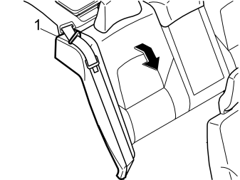
- Fold the right rear backrest forward
- Remove the seat belt from the guide (1).
Applies only to the S60
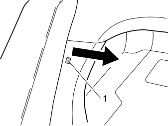
- Remove the clip (1) at the side of the right-hand side cushion
- Pull out the top edge of the left front panel in the cargo compartment to access the upper catch for the side cushion.
Applies only to the S60
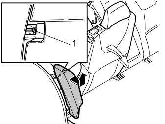
- Remove the right-hand side cushion. First press in the catches (1) at the top edge of the reverse of the side cushion. Pull the cushion out slightly
- Grasp the cushion using both hands. Twist the cushion clockwise until the catches on the inside release
- Remove the side cushion. First pull out the upper edge of the side cushion. Then pull upwards.
Applies to cars with mountings for Isofix on the right side of the rear seat
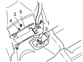
- Remove the screws (1). Slacken off the end mounting (2) for the seat belt
- Remove the nut (3) and the washer (4) from the stud
- Remove the mounting (5).
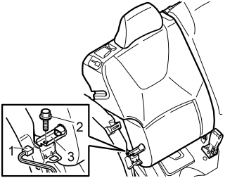
- Disconnect the connector (1) and the screw (2) on the right backrest
- Lift up the mounting (3). Gently work the backrest forwards and backwards to release the pin from the mounting in the left backrest
- Remove the right backrest.
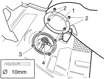
- Push the insulation panel to one side so that the cover (1) is accessible
- Remove the nuts (2) and the cover
- Drill out the connection (3) in the fuel tank unit (4). Use a 4 mm diameter drill bit.
Примечание: Use a compressed air power drill with a greased bit.
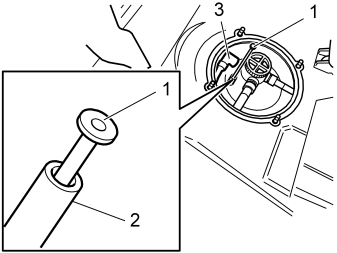
- Insert the pipe (1) into the connection (2). Press the tube down until it is in contact with the connection
- Install the masking tape on the end of the fuel hose before pushing the hose downwards
- Insert the entire hose (3) between the floor and the fuel tank out to the right.
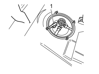
- Press the quick-release connector (1) onto the connection until it clicks. Check that the quick-release connector is secure.
- Reinstall the cover and the nuts (see point en-GB0900c8af80c4a072#KC01636832)
- Tighten the nuts
- Fold back the backrests, side cushions and seat cushions
- Open the expansion tank cap.
Exterior preparations
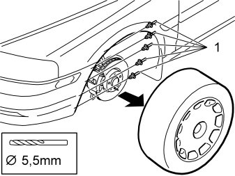
- Raise the car slightly
- Remove the left front wheel
- Raise the car a little more
- Drill out the five rivets (1) in the left, front edge of the wheel housing.
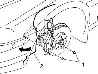
- Remove the two nuts (1) in the left fender liner (2). Bend the fender liner out of the way.
Applies only to models with an air baffle
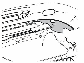
- Remove the screw (1) from the left air baffle (2) for the front brake
- Pull the left air baffle backwards. Remove the left air baffle. Remove the right air baffle in the same way.
Примечание: The left air baffle will not be reused.
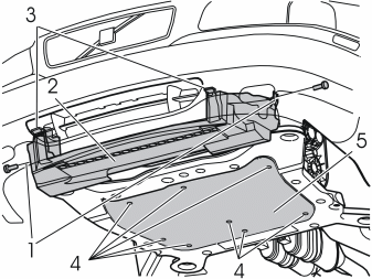
- Remove the screws (1). Remove the air baffle (2) by pressing in the catches (3)
- Remove the screws (4). Remove the engine splash guard (5)
- Thread a hose onto the engine coolant drain nipple
- Open the drain nipple. Drain off the coolant.
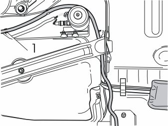
- Route the fuel supply hose forwards along the right-hand side of the fuel tank
- Route the fuel hose around the outside of the fuel pump (FP) and inwards, above the front mounting for the fuel tank
- Route the fuel hose along the front edge of the fuel tank and down alongside the other hoses behind the brake pipe. Allow the hose to hang
- Press the fuel hose into the existing clamp (1) in the rear edge of the right-hand side of the fuel tank.
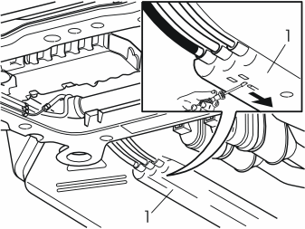
- Detach the fuel rail (1) at the front edge. First insert a small screwdriver into the small hole between the yellow clip and the fuel rail. Push the clip in the direction of the arrow. Repeat this for the other five clips
- Pull down the fuel rail so that it hangs from the hoses.
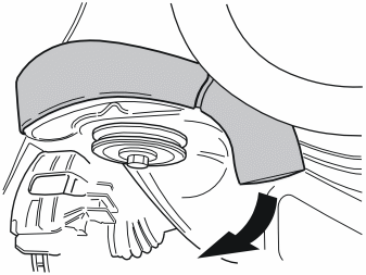
- Detach the pipe elbow from the front edge of the right-hand front corner of the sub-frame. Carefully pull forwards so that the clip on the reverse releases from the pipe elbow or from the sub-frame. This is to facilitate installation of the fuel line
- Fold the pipe elbow out of the way.
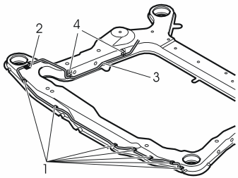
- Install the clips (1) and the fuel pipe on the sub-frame
- Push the removed pipe elbow to one side
- First secure the fuel line (3) in the double clamp (2). Then secure the fuel line in the existing clips (4). Finally secure the fuel line in the clips (1).
- Reinstall the pipe elbow.
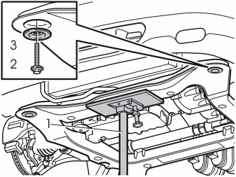
- Install the jack (1) under the front edge of the sub-frame
- Take the weight off the sub-frame
- Remove the screw (2) and the washer (3) from the left front mounting on the sub-frame.
Installing the parking heater
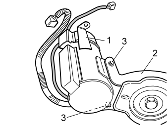
- Install the heater (1) on the bracket (2.) Use the screws (3) from the kit. Tighten.
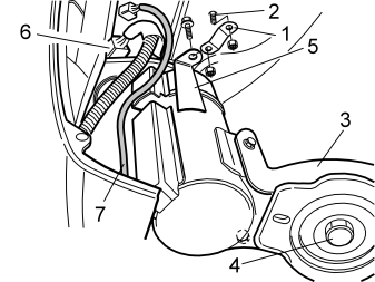
- Position the bracket (1) (from the kit) on the screw (2) protruding in the wheel arch
- Take a nut from the kit. Finger tighten
- Install the heater and the bracket (3) in the left front mounting on the sub-frame. Use the screw (4) from the kit. Finger tighten
- Turn the bracket (1) so that its hole is positioned opposite and underneath the hole in the bracket (5)
- Secure both brackets using the screw and nut from the kit. Finger tighten
- Check that the heater does not catch on any surrounding components
- Tighten the heater to the sub-frame and the brackets
- Tighten the screw (4). Tighten to 105 Nm (78 lbf.ft). Angle-tighten 120° or maximum 280 Nm (206 lbf.ft.)
- Remove the protective cover from the pre-routed connector (6). Press in the catches on the top of the connector to release the cover
- Connect the cable from the heater to the connector
- Insert the excess 2-pin cable (7) from the heater in the engine compartment through the hole in the bodywork at the left indicator lamp
- Remove the jack.
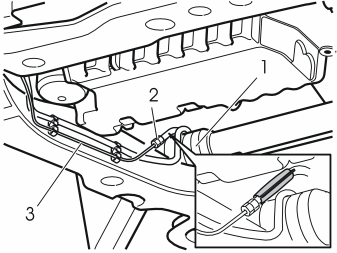
- Route the fuel hose over the steering gear (1). Connect the fuel hose to the quick-release connector (2) on the fuel pipe (3)
- Turn the hose guard so that the joint is not against the engine fuel lines.
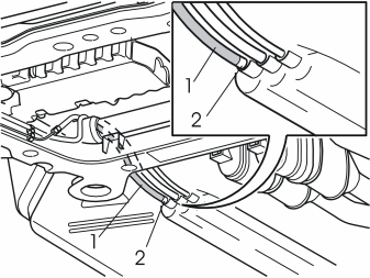
- Pull the fuel hose (1) backwards. Press the fuel hose into place with the taped surface (2) in contact with the fuel hose socket in the rail
- Press the fuel hose into the clamps in the bottom of the rail.
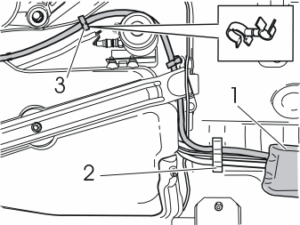
- Reinstall the fuel hose rail (1). See point en-GB0900c8af80c4a072#KC01636841
- Secure the fuel hose in the existing clamp (2). Also use the double clamp (3) from the kit at the brake pipe
- Distribute any excess sections of hose along the fuel tank.
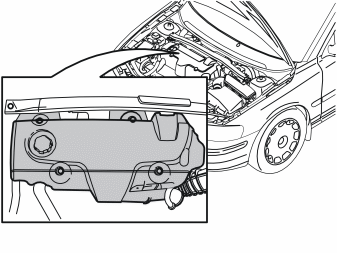
Remove:
- the four screws holding the engine cover
- the engine cover. Place the cover to one side.
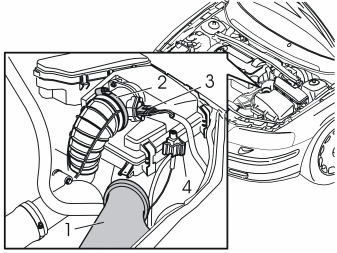
- Remove the intake manifold (1) from between the radiator and the air cleaner (ACL)
- Remove the hose clamp (2) on the hose between the air cleaner (ACL) and the intake manifold for the turbocharger (TC)
- Disconnect the connector (3) from the air cleaner (ACL)
- Remove the vacuum valve (4) with the hoses from the air cleaner (ACL). Bend out the catch from the rear edge. Pull the vacuum valve and hoses upwards
- Push the vacuum valve and hoses to one side so that do not impede work.
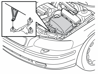
- Pull the air cleaner (ACL) from the three mounting points.
Примечание: To facilitate removal: Use a sleeve extension and a 10 mm sleeve to compress the mounting point catches. At the same time pull the air cleaner (ACL) upwards.
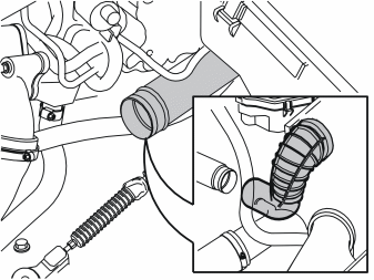
- Remove the rubber elbow from the pipe for the turbocharger (TC).
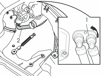
- Disconnect the quick-release connector on the left heating hose (1) for the passenger compartment heater. Press together the catch opposite the stamped arrows. Turn the catch in the direction of the arrow. Turn the connector slightly and pull it off
- Remove the hose clamp (2) from the other end of the heater hose by the radiator hose on the left-hand side of the cylinder head. Pull the heater hose off
- Remove the heater hose. Place the heater hose to one side. The heater hose will not be reused.
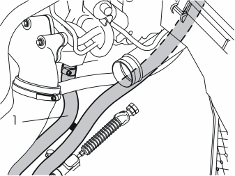
- Thread the heater hoses (from the kit) down into the front edge of the gearbox. Continue out to the front edge of the left-hand wheel arch. On cars with automatic gearboxes, route both heater hoses between the two oil hoses from the automatic gearbox
- Connect the shorter of the heater hoses to the radiator pipe (1) at the left-hand side of the front edge of the cylinder head. Tighten using a new hose clamp from the kit
- Route the longer of the heater hoses under the intake manifold to the turbocharger (TC) following the same route as the old heater hose. Connect the hose in position where the old hose was removed.
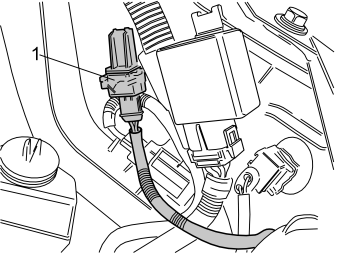
- Secure the 2-pin cable (1) (routed into the engine compartment in point en-GB0900c8af80c4a072#KC01636847) in the fender liner hole at the left-hand side of the air cleaner (ACL).
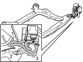
- Connect the two heater hoses (1) to the heater. Use the hose clamps from the kit
- Tighten.
Bleeding the fuel system
- Connect the fuel line (2) to a vacuum pump. Carefully apply suction until fuel comes out
- Connect the line (2) and hose (3).
Finishing work
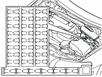
- Open the fuse holder cover in the engine compartment. Install a 25 A fuse in terminal 1
- Reinstall the cover.
- Tighten the drain nipple on the radiator. Remove the hose
- Reinstall the engine splash guard. Tighten to 25 Nm (18 lbf.ft)
- Reinstall the air baffle. First the centre air baffle and then the right-hand one
- Fold the fender liner back into position. Tighten the fender liner using the two nuts
- Rivet the front edge of the fender liner using the pop rivets from the kit
- Lower the car slightly. Reinstall the wheel. Tighten to 140 Nm (105 lbf.ft.).
- Lower the car completely
- Fill with coolant. Reinstall the expansion tank cap
- Reinstall the air cleaner and connections
- Start the engine. Bleed the radiator system
- Program the software. See the service information in VIDA
- Test the function of the heater according to separate instructions.
Обсуждение и оценка
0Пока нет комментариев. Будьте первым.