Применимость
| Модель | Двигатель | Год |
|---|---|---|
| C30 | — | 2009–2013 |
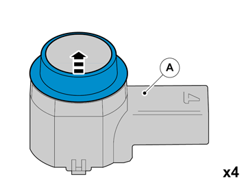
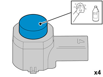
- Clean the sensors. Use: Isopropanol.
- Allow to dry.
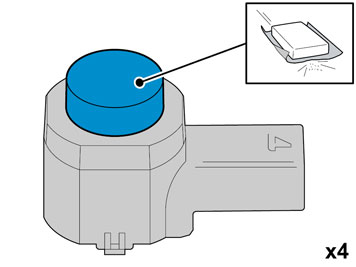
- Carefully mat the surface down. Use: Glasspaper, grade P1000
- Clean the sensors again. Use: Isopropanol
- Allow to dry.
- Avoid contact with the cleaned surfaces.
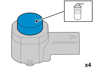
Осторожно: Protect the connections' contact surfaces against paint.
- Paint the sensors in the same colour code as the vehicle.
- Use Volvo Touch-up paint. (Only use base coat.)
- Use: Volvo 2-K Varnish. P/N: 31335447
Примечание: Also read the instructions on the spray can.
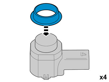
Осторожно: The paint must have dried after the first application.
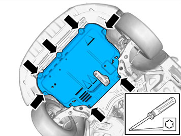
- Raise the car.
- Remove the screws and the engine splash guard.
Applies to vehicles with headlamp washing
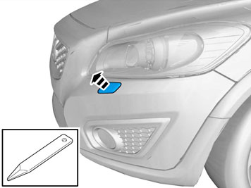
- Pull out the cover so that the nozzle is visible.
Applies to vehicles with headlamp washing
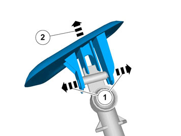
Осторожно: Do not damage painted surfaces and high pressure washer nozzles.
- Repeat steps 7-8 on the other side.
Applies to all models
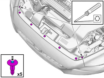
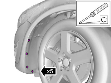
- Carry out on both sides.
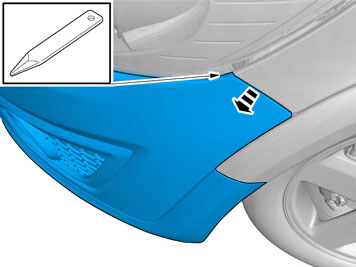
- Take a weatherstrip tool and pry between the headlamp bumper cover.
- Pull straight out until the catches release.
- Repeat the operation on the other side.
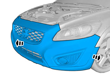
Подсказка: Removal of the bumper is facilitated if carried out by 2 people.
Applies to vehicles with fog lamps
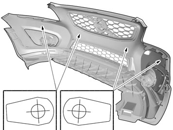
- Locate the 4 markings on the inside of the bumper cover.
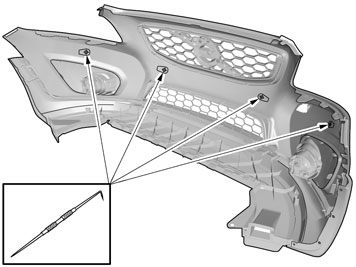
- Mark the center with a scribe.
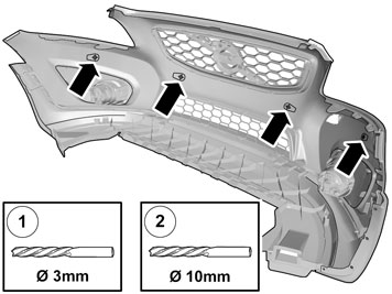
- Ø 3 mm (7/64")
- Ø 10 mm (25/64")
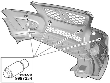
Use special tool: 9997234
Примечание: The hole tool's support sleeve must be on the inside, and the cutting part on the outside of the bumper casing.
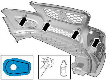
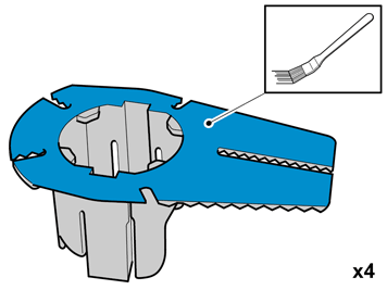
Use: Isopropanol
- Allow to dry.
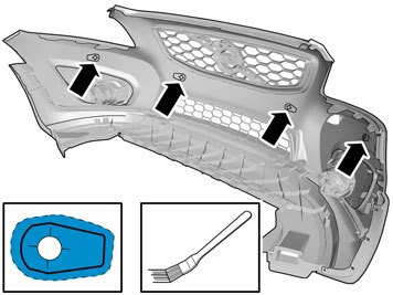
Use:8637076 - Activator
- Apply a thin and even layer.
Осторожно: Allow to dry for at least 10 minutes.
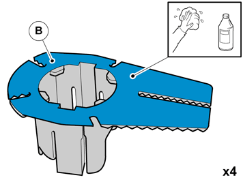
Use: Isopropanol
- Allow to dry.
Use:8637076 - Activator
- Apply a thin and even layer.
Осторожно: Allow to dry for at least 10 minutes.
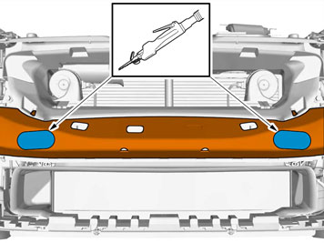
Примечание: There are two types of member (energy absorbing).
Plastic member:
- Saw along the 2 markings, only through the outer part.
Foam member (EPS):
- Remove the foam member from the collision member.
- Saw along the 2 markings.
- Reinstall the foam member.
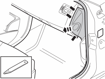
- Remove the panel.
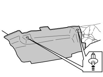
- Remove the 2 clips and the soundproofing panel.
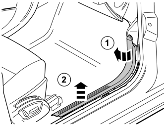
- Detach the front sill molding by first pulling it backwards at the front edge and then straight up so that the clips release.
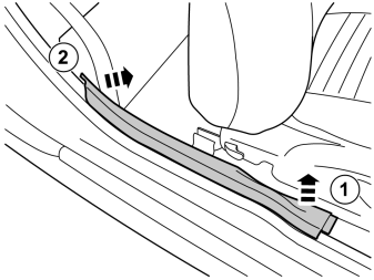
- Detach the rear sill molding by first pulling it up at the front edge, and then unhooking it at the rear edge.
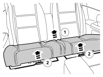
- Pull off the seat cushion for the rear seat, first at the rear edge where it is secured by one holder. Then at the front edge where it is secured by two holders.
- Remove the seat cushion.
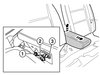
- Fold the central arm rest forward.
- Remove the central arm rest by grasping each end and pulling upwards until it releases at the rear edge from the backrest's lugs (1).
- Then pull forwards until the holders (2) on the sides of the backrest have slid out of the corresponding cut-out (3) in the central arm rest.
Note! Applies to right-hand drive vehicles. Points 29-39 must not be mirrored.
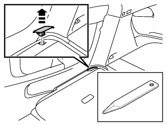
- Fold the backrest forward.
- Remove the cover for the backrest's right-hand mounting.
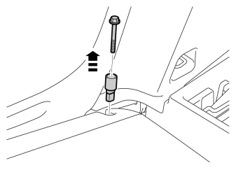
- Remove the screw and the locking sleeve.
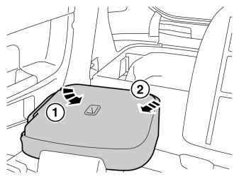
- Fold the backrest away from the right-hand mounting.
- Pull it out from the mounting at the arm rest and remove it.
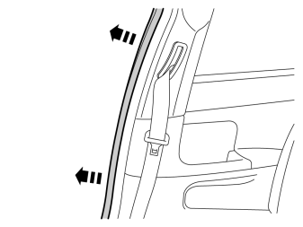
- Pull off the rubber molding at the rear edge of the right-hand door opening.
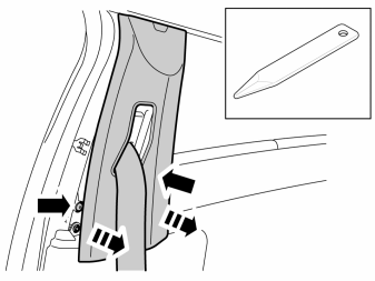
- Detach the B pillar panel at the rear edge by prying the sides using a weatherstrip tool until the 2 clips release.
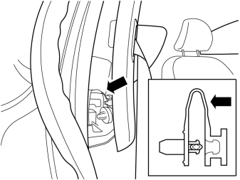
- Cut off the strap on the safety clip.
- Angle out the panel at the lower edge, and then unhook it at the upper edge so that the upper clip releases.
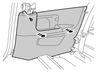
- Remove the screw from the right-hand panel in the rear seat.
- Carefully pull off the panel from the body side. It is secured by 11 clips on the inside.
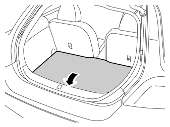
- Lift up the floor hatch at the rear edge.
- Pull it backwards so that it detaches at the front edge.
- Turn the cover and lift out.
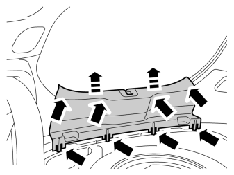
- Remove the tailgate's sill panel by pulling it up until the four clips on the upper side and the catches at the lower edge release.
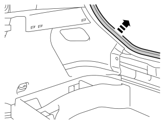
- Pull off the weatherstrip on the right-hand side in the cargo compartment's opening.
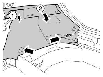
- Remove the clips at the rear edge of the right-hand rear side panel.
- Carefully pull the side panel off, starting at the front edge/upper edge and then straight back until all clips at the top edge have released.
- Fold the panel inwards. Release it from the anchorage eyelets and lift it out of the load floor support.
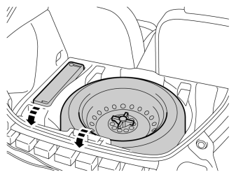
- Lift out the spare wheel, jack and other parts from the storage compartment in the cargo floor support.
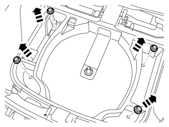
- Remove the 4 screw clips.
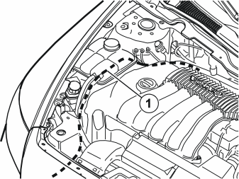
Примечание: Ensure that the cable harness does not lie against any moving components or too close to heat sources.
- Take the short cable harness from the kit.
- Remove the taped connector from the cable harness.
- Pull the end with the loose terminals in under the headlamp
- Continue to pull the cable harness (1) along the right-hand side of the car, under the expansion tank down to the cowl panel.
- Route the cable so that it is concealed and cannot be damaged or worn. Secure the cable harness using tie straps so that it does not move.
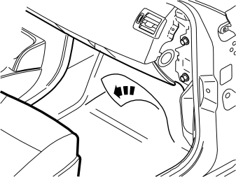
- Unscrew the clips holding the floor carpet.
- Push the floor carpet to one side to access the cowl panel inside.
- Take care not to create folds in the carpet.
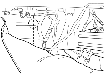
- Locate the hole for the rubber grommet under the insulation panel.
- Make a small cut in the insulation panel starting just above the hole, continue to the center of the hole and then straight down.
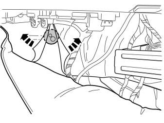
- Push the carpet tabs to one side to access the rubber grommet in the cowl panel.
- Remove the rubber grommet.
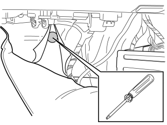
Примечание: Applies to cars with fuel-driven parking heater.
Protect the coolant hose on the water pump's horizontal connection when hole-marking.
- Pierce holes through the heat insulation panel and out into the engine compartment, for hole-marking in the heat insulation panel in the engine compartment.
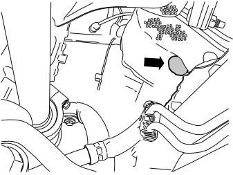
- Raise the car.
- Cut out a hole in the heat insulation that is approx. 20 mm (25/32") larger than the size of the rubber grommet.
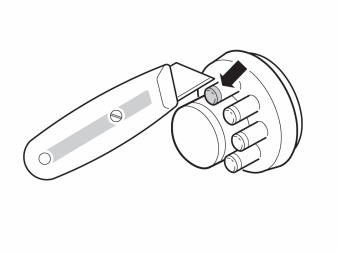
- Take the rubber grommet from the kit and cut the top off the smaller rubber nipples
- Lubricate the rubber grommet. Use low temperature grease (P/N 1161417).
- Thread the rubber grommet on the cable harness.
- Route the cable harness in through the hole and press the rubber grommet into the hole so that it seals properly.
- Make sure that the heating hose for the cable harness is in contact against the rubber grommet and secure it with a tie strap.
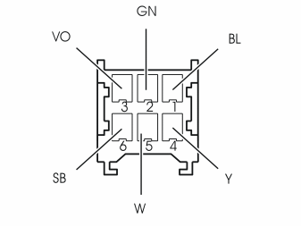
- Lower the car.
- Release the catch on the connector that was taped.
- Blue (BL)
- Green (GN)
- Violet (VO)
- Yellow (Y)
- White (W)
- Black (SB)
- Press back the connector's catch.
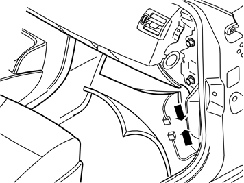
- Take the long cable harness from the kit. Connect it to the connector which has just been prepared.
- Route the cable harness from the lower edge of the A pillar and further back at the sill and under the carpet.
- Fold back the carpet and screw the clip into place.
Note! Applies to left-hand drive vehicles.
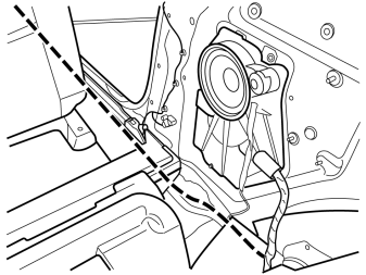
- Route the cable harness further back and under the seat support and backwards and into the cargo compartment, along the existing cable harnesses.
- Position the cable harness so that it does not get trapped or damaged.
Note! Applies to right-hand drive vehicles.
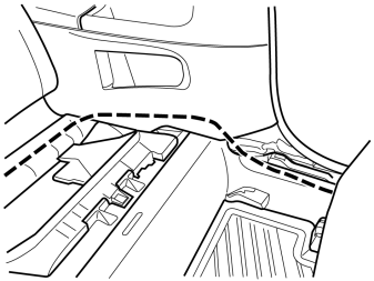
- Route the cable harness from the lower edge of the A pillar and further back under the carpet and behind the large side panel.
Note! Applies to right-hand drive vehicles.
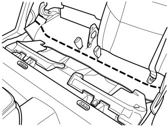
- Route the cable harness under the floor's insulation panel over to the right-hand side.
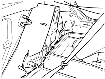
- Route the cable further along the existing cable harnesses backwards and into the cargo compartment, to the right rear corner of the cargo floor support.
- Position the cable so that is does not get trapped or damaged.
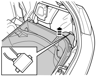
- Raise the right-hand side cargo floor support.
- Locate the parking assistance module (PAM). It is secured on the right-hand side of the cargo compartment floor, under the cargo floor support.
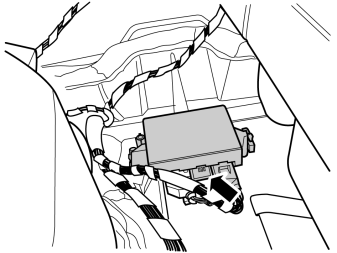
Примечание: Ensure that the connector's catch clicks and is securely positioned.
- Connect the pre-routed cable to the vacant connection (middle) on the parking assistance module (PAM).
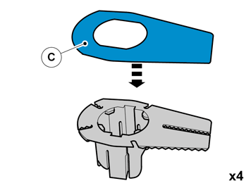
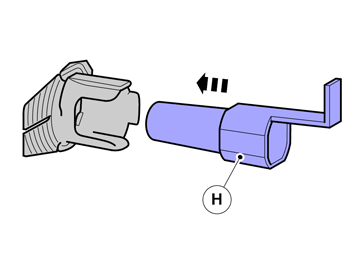
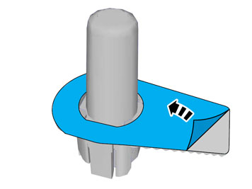
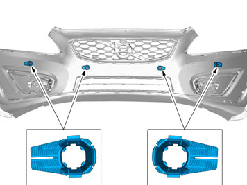
Примечание: The holders shall be installed facing in the direction as shown in the figure.
- Press in the cradle on the bumper cover.
- Repeat the steps for the other cradles.
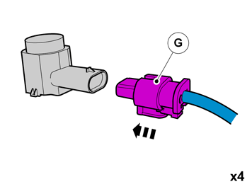
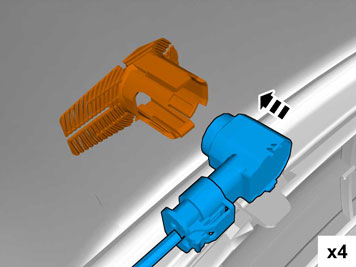
Примечание: On left-hand drive vehicles the large grey connector must be on the right-hand side of the bumper cover. On right-hand drive vehicles it must be on the left-hand side. (see point 64).
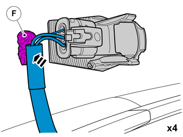
- Secure the end of the cable harness at the sensors to the bumper cover using butyl tape.
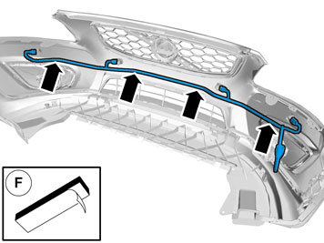
- Secure the cable harness to the bumper cover using butyl tape.
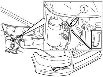
- Hold the bumper up against the car and connect the connector for the sensor cable to the connector at the car.
- Secure the assembled connector on the member (1). Use a tie strap on each side of the connector.
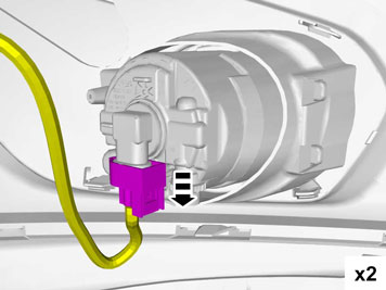
- Connect the connectors to any foglamps.
- Slide the bumper cover into the correct position
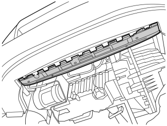
- Guide the lower edge of the bumper cover into the guides.
- Reinstall the bumper cover by repeating points 6 - 10 in reverse order.
- Reinstall the engine splash guard.
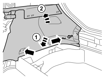
- Reinstall the side panel.
- Reinstall the clip for the cargo floor support.
- Reinstall the weatherstrip.
- Reinstall the sill trim panel.
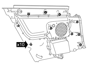
Примечание: There are ten clips on the reverse of the panel that must all engage in the body. Take care when aligning so that the clips do not break. Broken clips must be replaced with new ones.
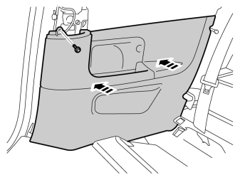
- Reinstall the side panel, ensure that all clips engage.
- Tighten the panel using existing screws.
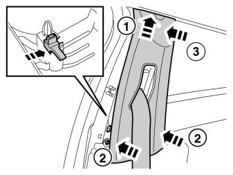
- Remove the 2 x parts of the cut-off safety clip.
- Take the safety clip from the kit, depress it and install it on the B pillar panel.
- Reinstall the panel and weatherstrip.
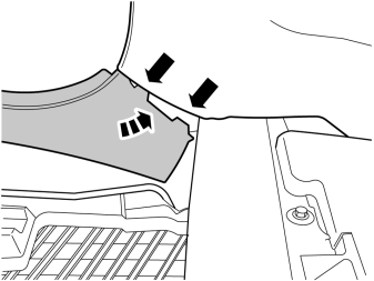
- Reinstall the rear sill trim panel, the 2 guides must be in the corresponding cut-outs in the side panel.
- Reinstall the front sill trim panel.
- Reinstall the backrest. Tighten the screws to 15 Nm (11 lbf.ft.).
- Reinstall the arm rest.
- Reinstall the seat cushion.

- Download software (application) for the accessory's function according to service information in VIDA. See VIDA or accessories catalogue for article number on software.
Обсуждение и оценка
0Пока нет комментариев. Будьте первым.