Применимость
| Модель | Двигатель | Год |
|---|---|---|
| C30 | — | 2008–2013 |
| S40 (04-) | — | 2008–2012 |
| V50 | — | 2008–2012 |
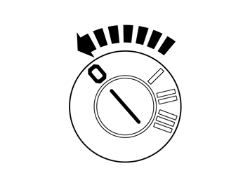
- Set the ignition key to position 0.
Примечание: Wait at least one minute before unplugging the connectors or removing other electrical equipment
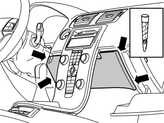
- Remove the panel inside the center console. It is secured by four hidden clips.
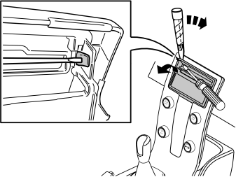
- Remove the surround from around the display and media player. Use a small screwdriver and press in the catch in one of the surround's upper corners. Carefully bend loose the surround on the same side with a plastic weatherstrip tool.
Примечание: Do not damage the panel and dashboard.
- Do the same on the other side.
Подсказка: If the panel is difficult to remove, press the panel on both sides again and repeat the procedure starting at the other side.
- Fold the surround backwards. Remove by pulling upwards.
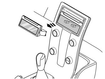
- Remove the infotainment control module (ICM). It is secured by two hidden clips. Disconnect the connectors.
Подсказка: Grip the control module with both hands. Pull the control module straight out of the center console.
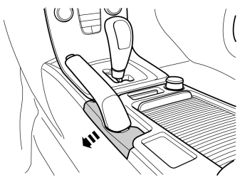
- Detach the panel by pulling it carefully sideways.
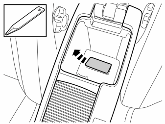
- Fold up the tunnel console's armrest and remove the cover.
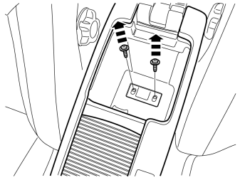
- Remove the screws.
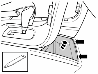
- Remove the front storage compartment by prying it off at the front edge using a weatherstrip tool and lifting it out.
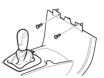
- Remove the two screws along the front edge of the tunnel console.
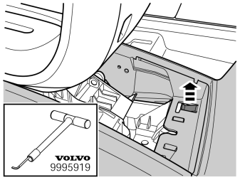
- Carefully lift the catches at the front edge of the tunnel console.
Подсказка: Use special tool: P/N 9995919.
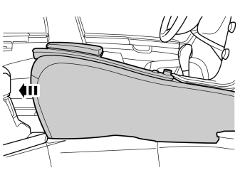
- At the same time pull the console backwards approximately 20 mm.
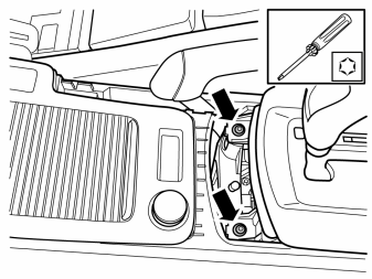
- Remove the screws.
Applies to vehicles with manual transmissions
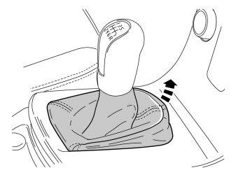
- Remove the gear selector lever boot from the center console. First pry it off at the front edge using a weatherstrip tool and then unhook it at the rear edge.
Applies to all vehicles
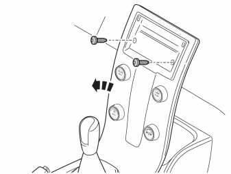
Remove:
- the two screws.
- the connector to the centre console at the rear.
- the centre console.
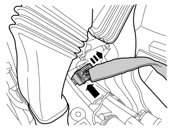
- Lift up the tunnel console and pull it back slightly.
- Unplug the big gray connector at the front.
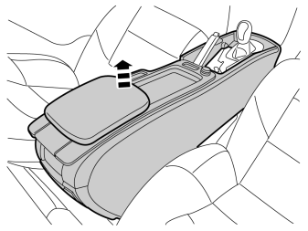
- Lift out the tunnel console and turn it upside down.
Примечание: Protect hand brake and gear lever when removing and installing the tunnel console.
Applies to vehicles with BLIS or DRIVe (not both)
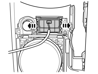
- Release the catches holding the switch housing and lift out.
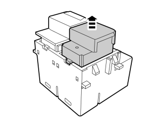
- Remove the blind cover plug by pulling it straight out.
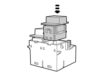
- Install the switch from the kit.
- Reinstall the switch housing on the tunnel console.
Applies to vehicles without BLIS and without DRIVe
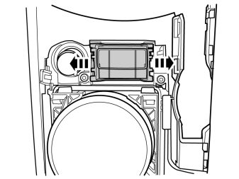
- Release the catches holding the switch connector and lift out.
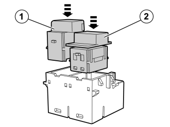
- Take the switch housing, switch and blind cover plug from the kit. Install the switch (1) and the blind cover plug (2) in the switch housing.
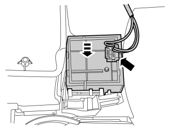
- Install the switch housing on the tunnel console.
- Take the cable harness from the kit and connect the blue connector.
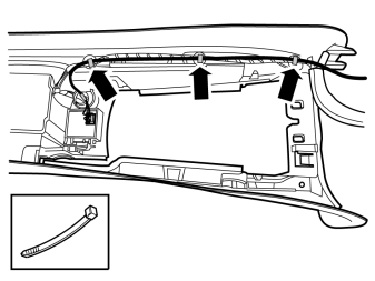
- Route the cable harness along the existing cable harness. Secure it using three cable ties.
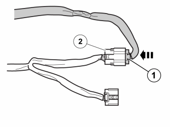
- Connect the connector (1) from the tunnel console's cable harness to the connector (2) on the prerouted cable harness.
- Take a piece of foam tape from the kit and wrap it around the connected connectors.
Applies to vehicles with both BLIS and DRIVe
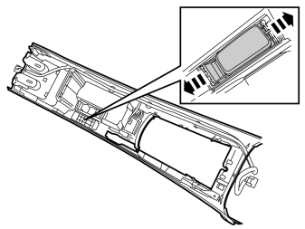
- Remove the storage compartment from the tunnel console by releasing the catches.
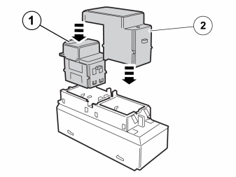
- Take the switch housing, switch and blind cover plug from the kit. Install the switch (1) and the blind cover plug (2) in the switch housing.
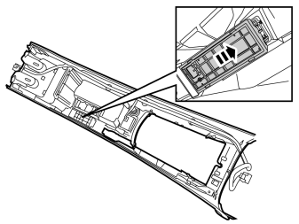
- Install the switch housing on the tunnel console by first hooking it at the rear edge.
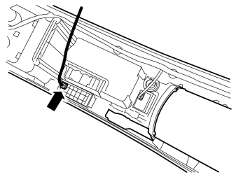
- Take the cable harness from the kit and connect the green connector to the switch housing.
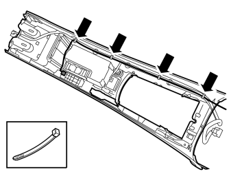
- Secure the cable harness using four cable ties at the existing cable harness.
- Connect the connector (1) from the tunnel console's cable harness to the connector (2) on the prerouted cable harness.
- Take a piece of foam tape from the kit and wrap it around the connected connectors.
Applies to all vehicles
- Reinstall the detached components in reverse order.
Applies to vehicles with both BLIS and DRIVe, as well as vehicles without BLIS and without DRIVe

- Run the identification and configuration procedure for the accessory's function according to the service information in VIDA.
Applies to vehicles with BLIS or DRIVe (not both)
- Run the configuration procedure for the accessory's function according to the service information in VIDA.
Обсуждение и оценка
0Пока нет комментариев. Будьте первым.