Применимость
| Модель | Двигатель | Год |
|---|---|---|
| S40 (04-) | — | 2004–2009 |
| V50 | — | 2004–2009 |
Примечание: The installation instructions describe connection to external and internal amplifier. The external amplifier located to the left in the cargo compartment and the internal amplifier is in the media player.
The following cars have an external amplifier: S40 CH -80922, V50 CH -78748, and all cars with the High Performance and Premium Sound audio systems.
The S40 CH 80823- and V50 CH 78749- with Performance Sound have an internal amplifier.
Примечание: When installing Velcro fasteners/tape the underlying surface must be kept at a temperature of at least +20° C (68°F).
Примечание: Steps 20, 37-50 and 63-78 only apply if the car shall be equipped with a traffic message (TMC) receiver (EU only)
Preparations
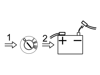
- Turn the ignition key to position 0.
- Disconnect the battery negative lead.
Примечание: Wait at least five minutes before disconnecting the connectors or removing other electrical equipment.
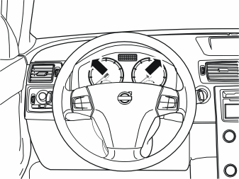
- Position the steering wheel in its lowest and rearmost position.
- Remove the two screws from the surround for the combined instrument panel.
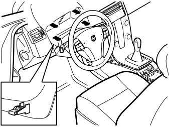
- Pull off the surround starting at the lower edge and then at the upper edge. The surround is secured by a clip at each side of the lower edge. Place the surround to one side.
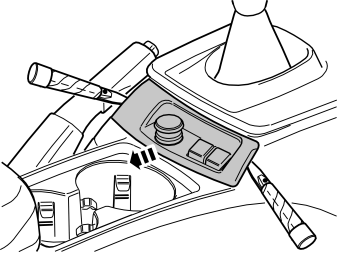
- Carefully prize off the panel at the rear edge of the centre console. Use a weatherstrip tool. The panel is secured by two clips on each of the short sides.
- Move the panel to the side to access the two screws underneath.
- Remove the two screws.
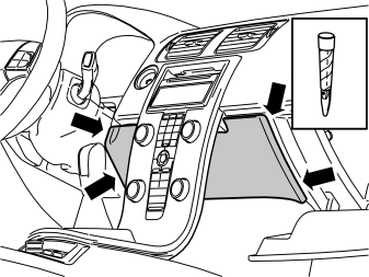
- Open the glove compartment.
- Carefully prize off the panel inside the centre console. Use a plastic weatherstrip tool. The panel is secured by two clips on each of the short sides.
- Pull the panel away downwards.
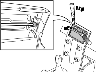
- Detach the surround around the display and the media player: Press in the catch at the edge of the media player cover. Use a small screwdriver. Carefully prize off the surround at the corner. Use a plastic weatherstrip tool.
Примечание: Do not damage the panel and dashboard.
Repeat the operation on the other side.
Подсказка: If the other side does not detach, press the detached side into position again and repeat the procedure, beginning from the other side.
- Fold the surround backwards. Remove by pulling upwards.
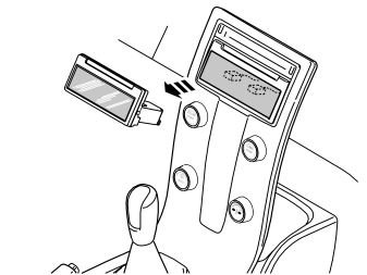
- Press out the display module (1) from the reverse of the centre console. Use both hands and press straight back.
- Disconnect the two connectors. Put the display to one side.
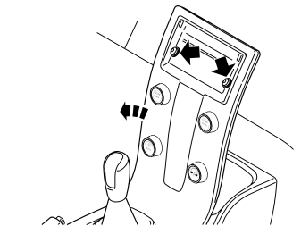
- Remove the two screws holding the centre console to the dashboard.
- Remove the connector on the reverse of the dashboard environment panel.
- Remove the centre console from the dashboard and tunnel console.
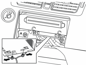
Only applies to the S40 CH 80923- and V50 CH 78749-
- Remove the two clips securing the cables to the media player by first pressing them to the sides and then pulling them away downwards.
Примечание: Be careful with the optic cables so that they are not bent or stretched.
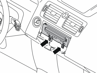
- Remove the two screws from the bottom of the media player.
- Pull out the media player. Disconnect the connector on the reverse side.
Примечание: Note how the wiring is packed on the reverse side. The fibre optic cables are easily damaged and must not be bent to a radius less than 25 mm (1 ¾").
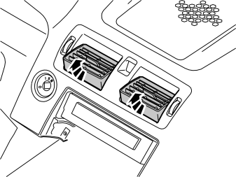
- Angle up both air vents.
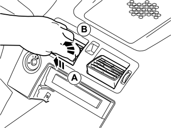
- Grip the air vent, press it out and pull it up.
- Do the equivalent to the other air vent.
Illustration A
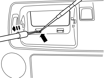
- Insert a scriber and push up one of the catches in the lower edge of the air vents' housing.
- Insert the tool P/N 9995919 in the space which is opened and pull out until the catch releases.
- Repeat this until all catches in the lower edge have released.
Illustration B
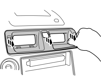
- Grip the ends of the housing and pull out until all catches on both the top and bottom are fully free from the inside of the dashboard. If necessary, use a weatherstrip tool to prize out the ends of the housing.
Примечание: Do not damage the dashboard.
Примечание: Pull alternately on the right and left-hand sides, otherwise the edge of the housing will crack where it enters the air ducts on the inside. The housing is secured firmly so force will be required to release it.
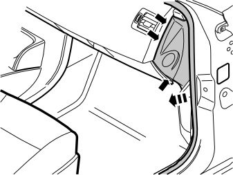
- Remove the panel on the right-hand end of the dashboard. Carefully prize off the panel until the three clips release. Use a weatherstrip tool.
Примечание: Do not damage the dashboard.
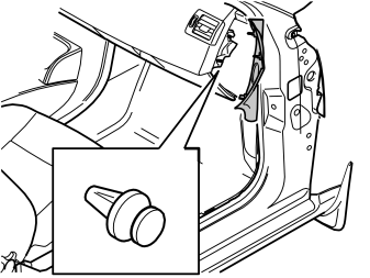
- Remove the clip which holds the vent to the air duct.
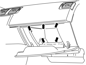
- Remove the rubber mat from the glove compartment.
- Remove the five screws in the opening to the glove compartment.
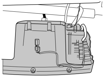
- Remove the front section of the glove compartment by pulling backwards until the two clips at the upper edge release. Disconnect the two connectors from the top.
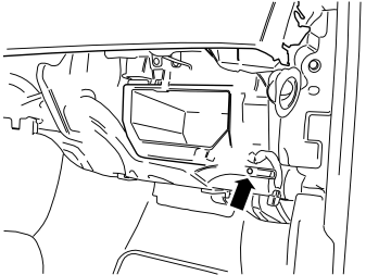
- Remove the screw for the vent on the right-hand side. Pull off the vent to the right. Place to one side.
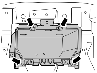
- Remove the four screws to the inner section of the glove compartment and pull it out. Place it to one side.
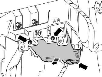
Applies to cars with integrated telephone and where the traffic message (TMC) control module shall be installed.
- Remove the screws in the phone module (PHM). Remove the control module, detach the connector on the rear side and place it to one side.
Installing the bracket for the remote control holder
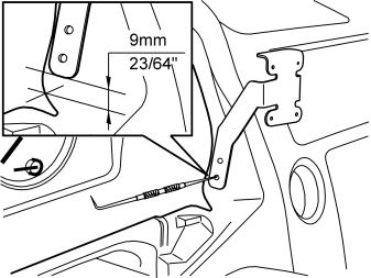
- Fit the support legs of the bracket from the kit into the socket for the surround of the combined instrument panel and in the left-hand air vent.
- Position the left-hand support leg of the bracket as illustrated. The front edge of the support leg must be parallel with the edge in the cut-out in the dashboard and the measurement to the bottom edge of the support leg must be taken from the centre of the radius.
- Mark out the holes to be drilled for the mounting.
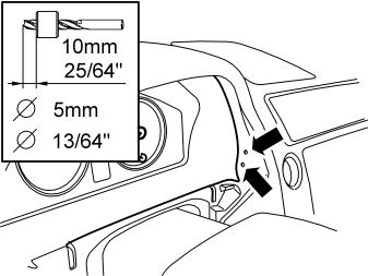
- Drill out the holes using a Ø5 mm (13/64") diameter drill bit. Use a 10 mm (25/64") drill stop to prevent damaging the components on the inside.
- Remove any swarf.
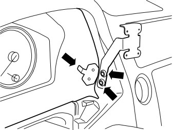
- Secure the left-hand support leg of the bracket to the dashboard using two screws and the mounting plate (located on the inside) from the kit.
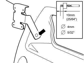
- Drill out the hole for the right-hand support leg using a Ø4 mm (5/32") diameter drill bit. Use a 10 mm (25/64") drill stop.
- Take a screw from the kit and secure the right-hand support leg.
Installing the screen bracket
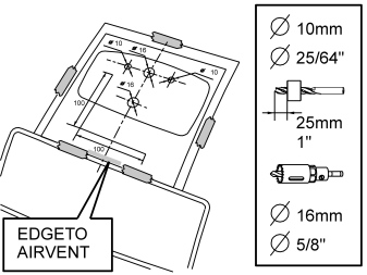
Applies to cars without loudspeaker grilles
- Tape the drilling template from the kit to the dashboard so that the angles in the lower edge of the template are edge to edge with the upper edge of the air vents, and the template is centred between them.
- Cover the holes in the air ducts on the inside so that the swarf from the drill cannot enter.
- Mark up and drill the holes, Ø10 mm (25/64") and Ø16 mm (5/8"), in accordance with the information on the template. Use an angle drilling machine, and keep it at right-angles to the dashboard. Use a 25 mm (1") drill stop on the 10 mm (25/64") diameter drill bit, so that the air ducts are not penetrated.
- Remove the drill swarf and the covering over the air ducts.
- Remove the drilling template.
Applies to cars with loudspeaker grilles
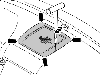
Illustration A
- Remove the loudspeaker grille as follows: insert the tool, P/N 999-5919-46, into the joint between the loudspeaker grille and the dashboard approximately as illustrated, until it engages.
- Twist the tool 90° so that the bent section engages with the underneath of the loudspeaker grille.
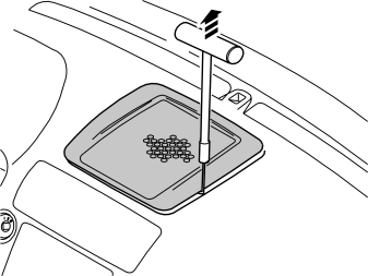
Illustration B
- Pull upwards until the loudspeaker grille detaches. The loudspeaker grille is securely fastened by five clips. Move the tool closer to the clips to facilitate removal.
Примечание: Do not damage the dashboard.
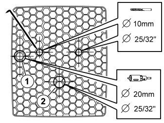
Applies to cars with loudspeaker grilles
- Mark out the holes on the underside of the loudspeaker grille using a scriber as illustrated. Drill out the holes in accordance with the specified dimensions. The centre for the Ø10 mm (25/64") holes and the Ø20 mm (25/32 ") hole (1) is in the centre of the hexagon. The centre for the Ø20 mm (25/32") hole (2) is slightly below the edge of the hexagon. Drill the Ø20 mm (25/32") holes from the top of the loudspeaker grille.
Примечание: Do not damage the loudspeaker grille.
- Smooth down the hole edges.
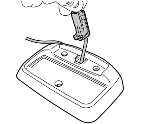
- Take the long cable with yellow connector and the bracket for the screen from the kit.
- Insert the yellow connector into the hole in the bracket, route through the cable and position the black connector in its socket.
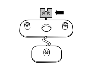
- Detach the screw plate away from the other installation components of the screen bracket.
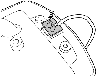
- Take the connector screw plate. Fit it in the rectangular cut-out on the underside of the bracket so that the semi-circular recess for the cable points forward as illustrated.
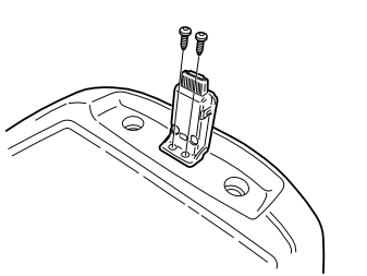
- Take two small self tapping screws from the kit and tighten the connector into the bracket.
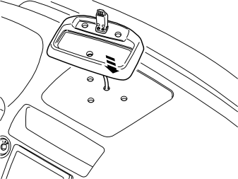
Applies to cars without loudspeaker grilles
- Guide down the yellow connector into the dashboard in the centre of the three holes which are in line with each other.
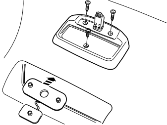
Applies to cars without loudspeaker grilles
- Fit the two screw plates from the kit on the underside of the dashboard.
- Take three screws from the kit, L = 30 mm (1 3/16") X 2 front and L = 20 mm (25/32" ) rear. Tighten the screen bracket into the dashboard.
Примечание: Re-tighten the screws at the next service interval.
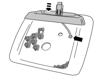
Applies to cars with loudspeaker grilles
- Guide down the yellow connector into the loudspeaker grille in the right-hand hole of the three holes and route through the cable.
Applies to cars with loudspeaker grilles
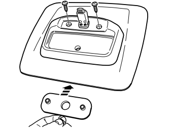
Illustration A
- Detach the two screw plates from each other.
- Fit the larger of the two screw plates on the underside of the loudspeaker grille. (The remaining small screw plate shall not be used.)
- Take two screws (L= 20 mm (25/32") from the kit and tighten the screen bracket into the dashboard.
Illustration B
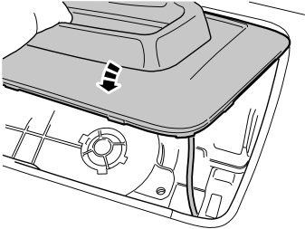
- Insert the cable in the dashboard in the hole in the bracket to the loudspeaker. Press in the loudspeaker grille.
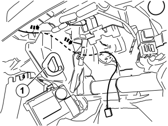
- Route the cable from the screen bracket to the right, past the compartment for the media player, down to the hole (1) where the detachable air duct was located. Continue to route the cable forward inside the cover and out where the glove compartment was located.
- Reinstall the air vents.
Installing the TMC antenna
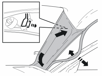
- Remove the weatherstrip for the door at the A-pillar.
- Pull off the panel from the A-pillar. The panel is secured by three clips.
- Lift the panel upwards and outwards.
- Unhook the clip nearest the roof.
- Remove the panel.
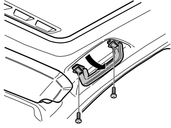
- Fold down the grab handle on the front right-hand side.Remove the two screws and detach it from the roof panel.
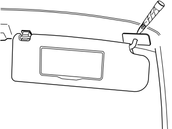
- Carefully prize away the cover over the screws to the right-hand sun visor's right-hand mounting using a weatherstrip tool.
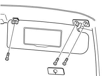
- Detach the sun visor from its left-hand mounting.
- Remove the screw in the mounting and remove it from the roof panel.
- Remove the two screws in the right-hand mounting and detach the sun visor from the roof panel.
- Detach the connector on the inside of the roof panel and remove the sun visor.
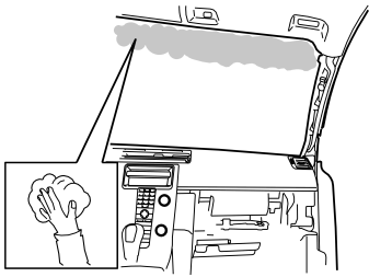
- Cleaned the marked surface in the black frame on the inside of the windscreen where the antenna strip shall be located. Use the cleaning cloth from the kit. Wipe dry.
- Heat the windscreen where the antenna strip shall be adhered using a hot-air gun to 45°C (113°F), in order to obtain the best possible adhesion.
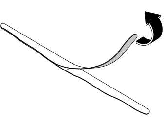
- Remove the protective backing tape on the transparent antenna strip from the kit.
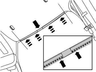
- Press in the antenna strip centred on the right-hand section of the windscreen, edge to edge with the black dots on the windscreen and roof panel. The straight edge of the antenna strip must be turned toward the roof panel. Press it in firmly so that no bubbles form.
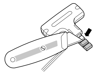
- Take the antenna box with cables from the kit. Cut off the whole of the bar at the innermost marking as illustrated.
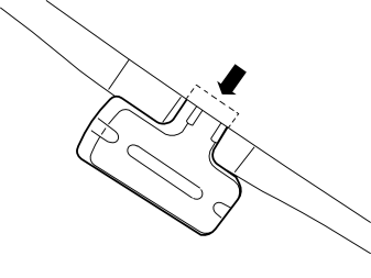
- Locate the antenna box just in front of the light rectangle on the recently installed antenna strip, with the cables pointing to the top of the windscreen.
- Cut out a little of the front edge of the roof panel for the protruding thicker part of the antenna box.
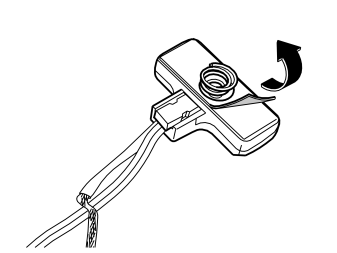
- Remove the protective backing tape from the antenna box.
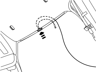
- Press in the antenna box centred on the rectangular surface on the recently installed transparent antenna section. The cables and the thick protruding part must point upward. Press firmly so that it is secure.
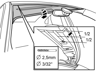
- Carefully bend the roof panel down at the right-hand front corner for drilling the hole for the antenna box ground cable. Position a spacer between the windscreen and roof panel to gain access for drilling.
Примечание: Do not damage the roof panel.
- Drill out the hole using a Ø2.5 mm (3/32") diameter drill bit as illustrated.
- Remove any drill swarf. Rust-proof the edges of the holes.
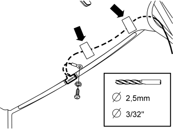
- Route the ground cable to the drilled hole. Take a toothed washer and screw from the kit and tighten in the ground cable.
- Route the longer of the cables inside the front edge of the roof panel and out to the right.
- Clamp it in to the inside of the roof panel using pieces of butyl tape.
Внимание: Do not damage the inflatable curtain.
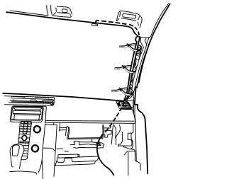
- Route the thicker cable along the existing cable harness at the A-pillar and into the dashboard and out in the area where the glove compartment was located.
- Clamp in the cable at the existing cable harness using three tie straps from the kit.
Внимание: Do not damage the inflatable curtain.
- Reinstall the sun visor, grab handle and A-pillar panel.
Installing the GPS antenna
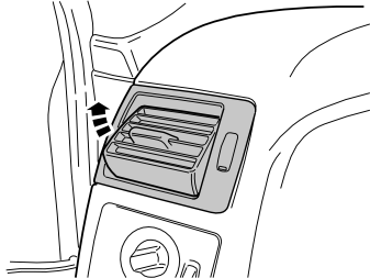
- Angle up the left-hand air vent.
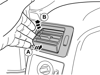
- Grip the air vent, press it in and pull it up.
Illustration A
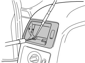
- Insert a scriber and push up one of the catches in the lower edge of the air vents' housing.
- Insert the tool P/N 9995919 in the space which is opened and pull out until the catch releases.
- Repeat this on the other catch in the lower edge.
Illustration B
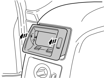
- Grip the ends of the housing and pull out until all catches on both the top and bottom are fully free from the inside of the dashboard. If necessary, use a weatherstrip tool to prize out the ends of the housing.
Примечание: Do not damage the dashboard.
Примечание: Pull alternately on the right and left-hand sides, otherwise the edge of the housing will crack where it enters the air ducts on the inside. The housing is secured firmly so force will be required to release it.
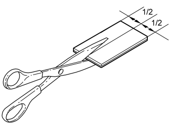
- Take the larger of the pieces of double-sided adhesive tape from the kit and cut it into two equal pieces.
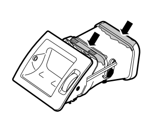
- Clean the two marked surfaces on the front part of the air vent using isopropanol P/N 1161721. Wipe dry.
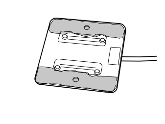
- Take the GPS antenna from the kit and clean the two marked surfaces on the underside using isopropanol P/N 1161721. Wipe dry.
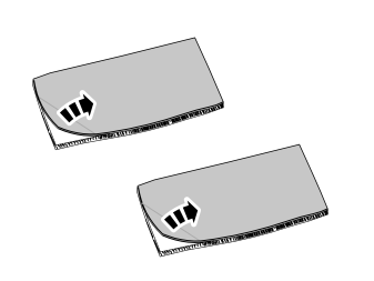
- Remove the protective backing tape from one side of the two pieces of tape.
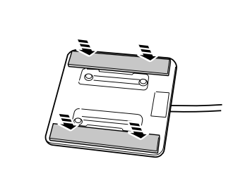
- Firmly press in the two pieces of tape on the underside of the GPS antenna.
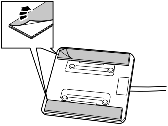
- Remove the last piece of protective backing tape from the two pieces of tape.
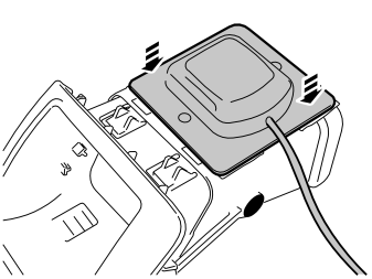
- Firmly press in the GPS antenna on the front part of the air vent.
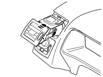
- Fit the air vent with the cable in place in the dashboard and press in. The top of the GPS antenna may offer a little resistance in the top edge of the cut-out.
Illustrations A and B
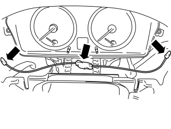
- Route the cable from the GPS antenna to the right in front of the driver information module (DIM), past the compartment for the media player, down to the hole (1) in illustration B, where the detachable air duct was located. Continue to route the cable forward inside the cover, and then out where the cable to the screen was routed.
- Secure the cable at the driver information module (DIM) using pieces of butyl tape.
- Reinstall the combined instrument panel surround.
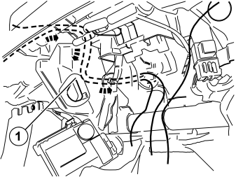
Installing the traffic message channel module (TMC)
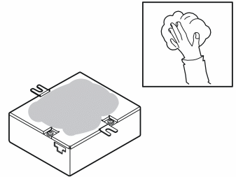
- Take the TMC unit from the kit and clean the marked surface on the underside using isopropanol P/N 1161721. Wipe dry.
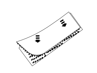
- Take the two long Velcro fasteners from the kit and press them together.
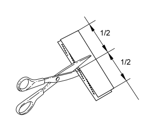
- Cut the Velcro fasteners into two equal pieces.
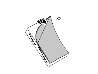
- Remove the protective backing tape from one side of the Velcro fasteners which were pressed together.
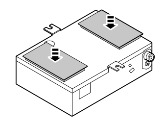
- Firmly press in the Velcro fasteners on the underside of the TMC unit.
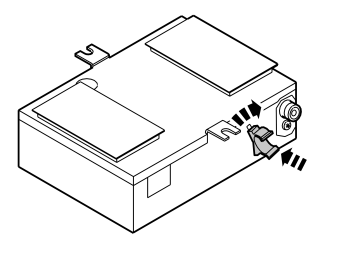
- Take the holder to the adapter connector from the kit and press/twist in at the rear edge of the TMC unit.
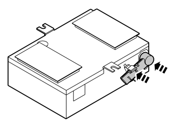
- Take the adapter connector from the kit and press in the connector into the rear edge of the TMC unit.
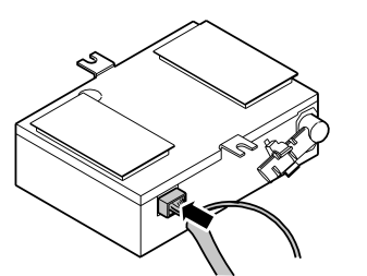
- Take the long cable harness from the kit and plug the white connector into the rear edge of the TMC unit.
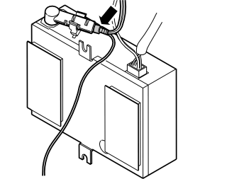
- Connect the routed cable from the antenna in the windscreen to the adapter in the rear edge of the TMC unit.
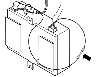
- Take the red crimping sleeve from the kit. Join the single cables from the white connector and the connector to the antenna in the rear edge of the TMC unit, in accordance with steps 73-75.
Splicing the cable
Splicing with insulated damp-sealed crimping sleeve
Illustration A
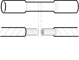
Select a suitable crimping sleeve according to the cables' area in accordance with the table:
| Colour | Cable area mm² | Stripping length mm |
|---|---|---|
| Green/White | 0.3 -0.5 | 5 |
| Red | 0.5 - 1.0 | 6 |
| Blue | 1.0 - 2.5 | 7 |
| Yellow | 4.0 - 6.0 | 7 |
Illustration B
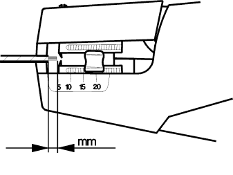
- Strip both cable ends in accordance with the above table. Use stripping pliers, P/N 9512620.
Pressing the sleeve
Illustration A
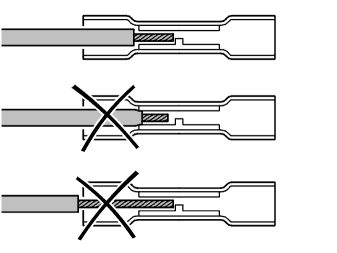
- Fit the red crimping sleeve in the press tool P/N 9512785. Select the socket as per colour coding. Clamp the pliers together slightly, but only so that the crimping sleeve remains in the pliers.
- Insert the cable in the crimping sleeve until it reaches the stop.
Примечание: Make sure that the cable insulation does not come into the press area of the sleeve or that the stripped part or the cable extends outside of the sleeve.
Illustrations B and C
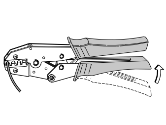
- Press the legs of the pliers completely together to ensure a proper splice. The pliers will then release automatically.
- With your hand, check that the crimping sleeve is securely in place.
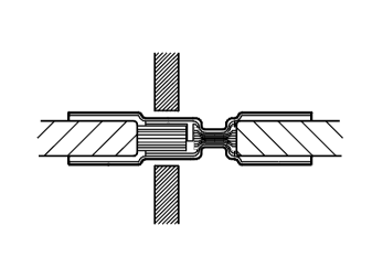
Heating the crimping sleeve
Illustrations A and B
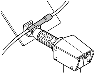
- Place a suitable shield behind the cables to be crimped to prevent thermal stress to the surrounding area.
- Warm the sleeve with a hot air gun, P/N 9512777, and suitable nozzle. It is extremely important that the crimping sleeve be securely crimped around the cable. You should be able to see that a little bit of glue has been forced out around the cable. (Illustration B).
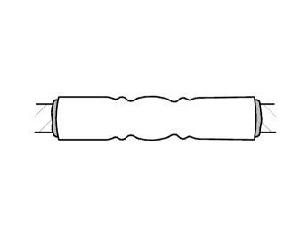
Installing the traffic message channel module (TMC), continued
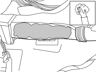
- Clean the marked surface on the underside of the air duct using isopropanol P/N 1161721. Wipe dry.
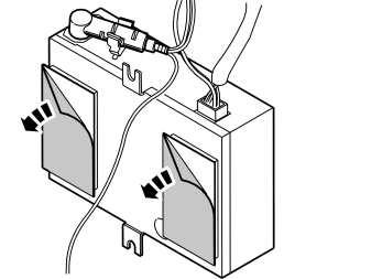
- Remove the protective backing tape from the double Velcro fasteners on the TMC unit.
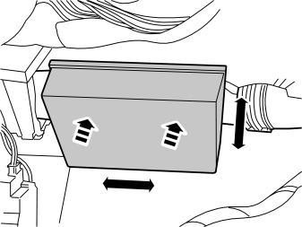
- Guide the TMC unit with the connectors pointing forward up toward the underside of the air duct. Position it so that it does not press against surrounding components, and firmly press it in.
Applies to cars with integrated telephone:
- Reinstall the phone module (PHM) on the underside.
- Torque tighten the two screws to 10 Nm (7.5 lbf.ft.).
Connecting to the central electronic module (CEM)
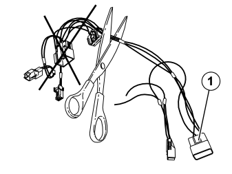
Only applies to the S40 CH -80922 and V50 CH -78748
- Take the adapter cable (1), P/N 30737807, with two small, two large grey and two black connectors from the kit.
- Cut off the three cables - red (R), violet (VO) and brown (BN) - as close as possible to the two grey connectors.
- Place to one side the grey connectors with the cables which were cut off, they shall not be used again. The large black connector (1) with associated cables shall later be connected to the corresponding connector in step 94.
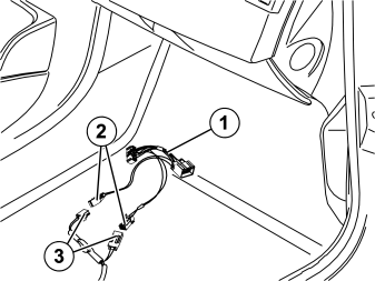
Applies to cars with internal amplifier
- Take the adapter cable (1), P/N 30737807, with two small, two large grey and two black connectors from the kit.
- Applies to cars with TMC unit: Plug the two small grey connectors (2) into the corresponding grey connectors (3) in the cable harness from the TMC unit.
- Applies to cars without TMC unit: Take the long cable harness from the kit. Plug the two small grey connectors (2) from the adapter cable into the corresponding grey connectors (3) in the long cable harness.
Applies to all models
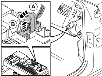
- Detach the 32-pin connector in the central electronic module (CEM) by first moving the connector's brace (A) backward, and then detaching the connector (B) upward.
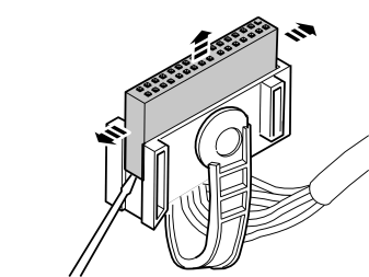
- Remove the secondary catch on the connector by first prizing out both catches at the short sides, and then remove the catch upward. Use tool P/N 9512639.
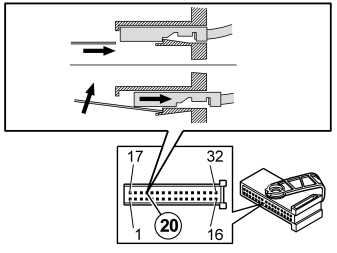
- Remove the cable from position 20 (only certain car models have this cable connected) by carefully inserting the tool, P/N 9512639 as illustrated, and then disengaging the primary catch while pulling out the cable.
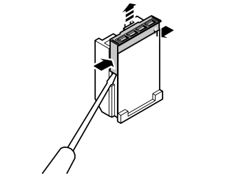
- Dismantle the 4-pin loose black connector from the adapter cable, P/N 30737807. Remove the connector's secondary catch by first prizing out the two catches at the short sides and then pulling the catch outward.
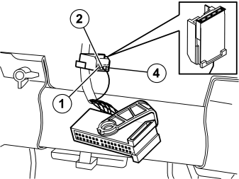
- Plug the cable previously detached from position 20 in the 32-pin connector into position 2 on the loose 4-pin black connector.
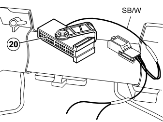
- Install the loose short insulated black/white (SB/W) cable for the speed signal on the adapter cable (P/N 30737807) in the 32-pin connector, instead of the one previously removed from position 20.
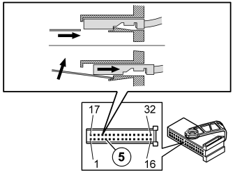
- Remove the cable from position 5 (only certain car models have this cable connected) by carefully inserting the tool, P/N 9512639 as illustrated, and then disengaging the primary catch while pulling out the cable.
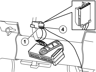
- Plug the cable previously detached from position 5 in the 32-pin connector into position 1 on the loose 4-pin black connector.
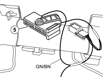
- Install the loose short insulated green/brown (GN/BN) cable for the reversing signal on the adapter cable in the 32-pin connector, instead of the one previously removed from position 5.
- Reinstall the secondary catch.
Illustration A
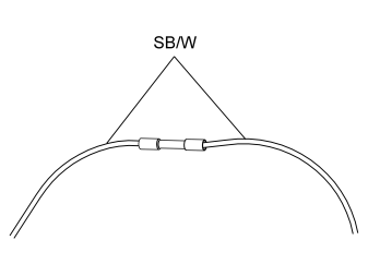
- Take the red (R) crimping sleeve from the kit.
- In accordance with steps 73-75, splice the black/white (SB/W) cable in position 3 from the 4-pin connector (illustration B), together with the long black/white (SB/W) cable in the routed cable harness.
Illustration B
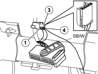
Applies to cars with internal amplifier
- Cut off unnecessary excess from the long black/white (SB/W) cable before splicing.
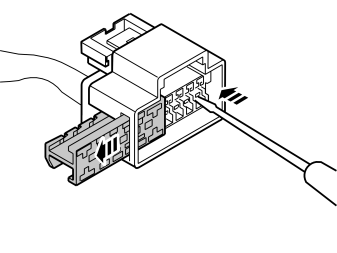
- Press out and remove the secondary catch on the large black male connector in the routed cable harness.
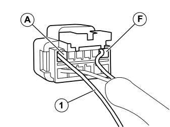
- Take the short cable with cable terminal (1) from the kit and press it into position (A) in the connector.
- Reinstall the secondary catch.
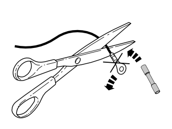
- Cut off the existing cable terminal on the long brown (BN) cable to ground in the routed cable harness.
- Splice the cable together with the cable in position A in step 92, with the red (R) crimping sleeve from the kit.
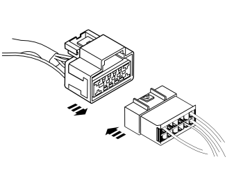
- Plug both large black connectors from the routed cable harnesses into each other.
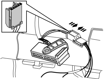
- Plug the two 4-pin black connectors into each other.
- Reinstall the 32-pin connector in the central electronic module (CEM).
Installing the CD drive
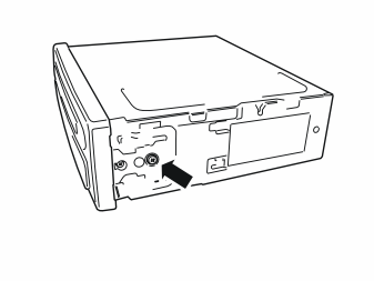
- Take the CD drive from the kit. Remove the screw to the adapter, and remove the adapter on the side of the CD drive. Do this on both sides. The parts shall not be used again.
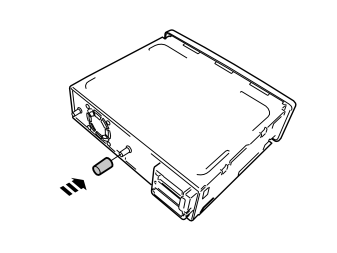
- Take the rubber spacer from the kit and install it on the CD drive.
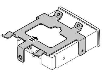
- Take the bracket from the kit and install it on the CD drive.
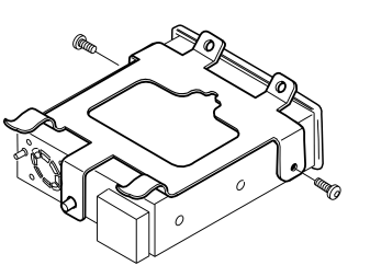
- Take two small screws from the kit and tighten the bracket into the CD drive.
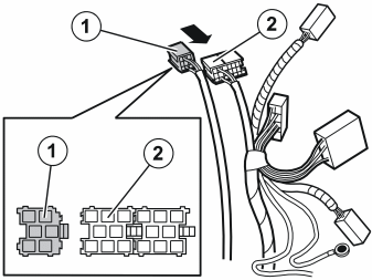
- Attach the yellow (1) connector from the screen to the green connector (2) on the routed cable harness.
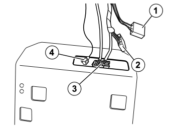
- Take the new inner glove compartment section from the kit. Insert the brown (1), black (2) and multi-coloured (3) connector, and the cable with the blank connector (4), through the hole in the rear edge of the glove compartment section.
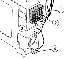
- Take the CD drive with bracket and plug in the connectors:
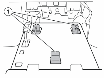
- Fit the CD drive in the inner section of the glovebox with the hooks (1).
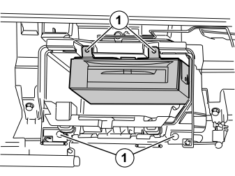
- Fit the inner section of the glove compartment in its correct position.
- Take the screws (1) previously removed and tighten in both the CD drive bracket and the glovebox section.
Connecting the media player
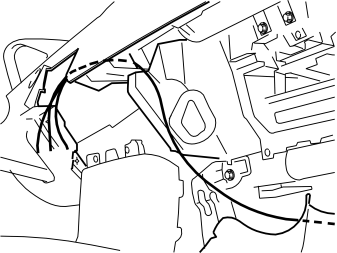
Only applies to the S40 CH -80922 and V50 CH -78748
- Route the cable harness with the three cables, red (R), violet (VO), and brown (BN) (where the connectors were cut off in step 79) down in front of the central electronic module (CEM). Route the cable harness inside the carpet to the left, along the right-hand side of the centre console, up along this and out where the media player was fitted.
- Bind in the loose connectors and fuse holder with foam tape from the kit to avoid rattling. The long foamed section of the cable harness with the two grey connectors shall later be routed under the floor carpet out toward the right-hand front door, to be later routed backward to the amplifier in the cargo compartment.
Steps 106 - 110 apply to the S40 CH 80923- and V50 CH 78749-
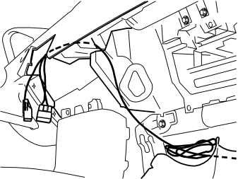
- Route the cable harness with the two large grey connectors down in front of the central electronic module (CEM), inside the carpet to the left, along the right-hand side of the centre console, up along this and out where the media player was fitted. The whole of the excess length of cable with the long foamed cable harness shall be located inside the carpet on the right-hand side of the centre console.
- Bind in the loose connectors and fuse holder with foam tape from the kit to avoid rattling.
Applies to right-hand drive cars
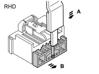
Illustration A
- Detach the secondary catch on the grey connector in the cable harness which was routed up in the previous step, press the catch down in the centre of the lower edge and pull the catch out against the stop. Use the tool, P/N 9512639.
Illustration B
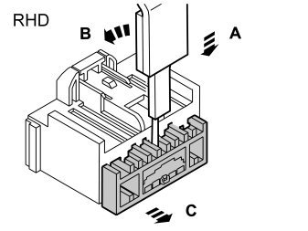
- Remove the catch by pressing it down in the centre of the top edge until the small lug on the top is free, and prize it out.
Applies to right-hand drive cars
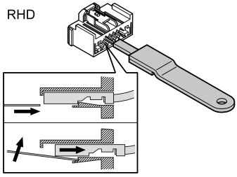
Illustration A
- Remove the cables from position 4, yellow (Y), and position 5, grey (GR). Carefully insert the tool, P/N 9512639 as illustrated, detach the primary catch and at the same time pull out the cables.
Illustration B
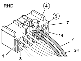
- Change places on both cables so that the positions are as illustrated.
- Reinstall the secondary catch.
Illustration C
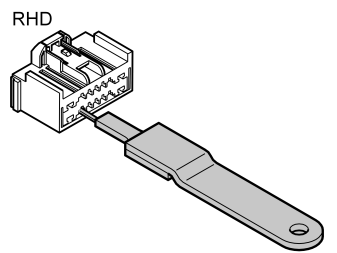
- Remove the cables from position 11, yellow/red (Y/R), and position 12, grey/red (GR/R), in the same way as in step 107A above.
Illustration D
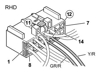
- Change places on both cables so that the positions are as illustrated.
- Reinstall the secondary catch.

Applies to right-hand drive cars
- Remove the secondary catch on the grey female connector. Carefully prize out the catches at the sides and move them forward. Pull out the catch.
- Now change positions on the same cables in the connector, as those in the previous steps for the male connector (4-5, 11-12).
- Reinstall the secondary catch.
Applies to all models
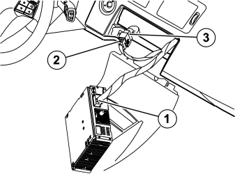
- Connect the grey connector (1) in the routed cable harness to the corresponding socket in the media player.
- Connect the grey connector (2) in the routed cable harness to the grey connector (3) which was detached from the media player.
- Plug the remaining connectors which where detached into the media player.
- Reinstall the media player and secure it.
Steps 111 - 116 apply to the S40 CH -80922 and V50 CH -78748
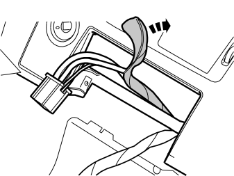
- Locate the black connector to the media player. Expose the cables from their foam for a length of about 150 mm (6").
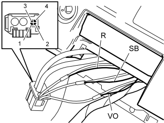
- Cut off the cables in position 1, 2 and 4 so that the crimping sleeves at the splicing are pushed from each other as illustrated.
- Now connect the three cables routed in step 102, to the three cables in the connector to the media player, with blue (BL) crimping sleeves from the kit in accordance with the following:
Splicing with crimping sleeves is performed in accordance with steps 113 - 115 below.
Splicing the cable
Splicing with insulated damp-sealed crimping sleeve
Illustration A
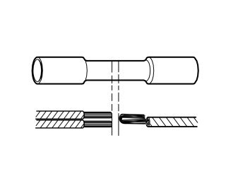
Select a suitable crimping sleeve according to the cables' area, in accordance with the table:
| Colour | Cable area mm² | Stripping length mm |
|---|---|---|
| Green/White | 0.3 - 0.5 | 5 |
| Red | 0.5 - 1.0 | 6 |
| Blue | 1.0 - 2.5 | 7 |
| Yellow | 4.0 - 6.0 | 7 |
If the cables have so large an area deviation that they do not fit the same crimping sleeve, then select the crimping sleeve according to the thicker of the cables.
- Strip the thicker cable. See table.
- Strip the thinner cable to double the length and double over the stripped section.
Illustration B
- Strip the three cable ends in accordance with the above table. Use stripping pliers, P/N 9512620.
Pressing the sleeve
Illustration A
- Fit the crimping sleeve in the press tool P/N 9512785. Select the socket as per colour coding. Clamp the pliers together slightly, but only so that the crimping sleeve remains in the pliers.
- Insert the cable in the crimping sleeve until it reaches the stop.
Примечание: Make sure that the cable insulation does not come into the press area of the sleeve or that the stripped part or the cable extends outside of the sleeve.
Illustrations B and C
- Press the legs of the pliers completely together to ensure a proper splice. The pliers will then release automatically.
- With your hand, check that the crimping sleeve is securely in place.
Heating the crimping sleeve
Illustrations A and B
- Place a suitable shield behind the cables to be crimped to prevent thermal stress to the surrounding area.
- Warm the sleeve with a hot air gun, P/N 9512777, and suitable nozzle. It is extremely important that the crimping sleeve be securely crimped around the cable. You should be able to see that a little bit of glue has been forced out around the cable. (Illustration B).
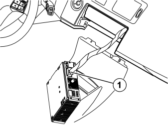
- Plug the black connector (1) into the corresponding socket in the media player.
- Plug the remaining connectors which where detached into the media player.
- Reinstall the media player and secure it.
Connecting the external amplifier
Примечание: Steps 117 - 147 apply to cars with external amplifier.
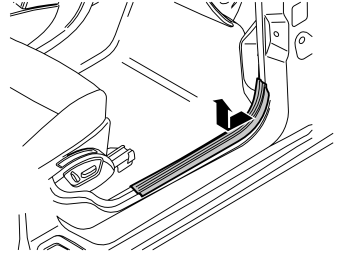
- Remove the sill trim panel at the right-hand front door. First pull off the front edge of the sill trim panel so that the clip releases. Then continue backward until the remaining clips on the underside have released.
- Unhook the sill trim panel from the B-pillar panel.
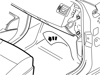
Applies to cars without a passenger compartment connector socket
- Push the floor carpet to one side in order to route the cable harness toward the rear of the car.
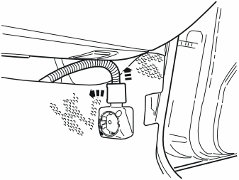
Applies to cars with a passenger compartment connector socket
- Remove the locking sleeve over the cable splice in the passenger compartment connector socket.
- Disconnect the cable from the passenger compartment connector socket.
- Remove the passenger compartment connector socket from its bracket.
- Push the floor carpet to one side in order to route the cable harness toward the rear of the car.
Steps 120–126 apply to the V50
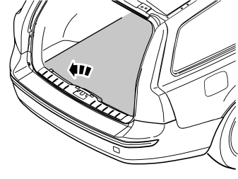
- Remove the cargo compartment carpet.
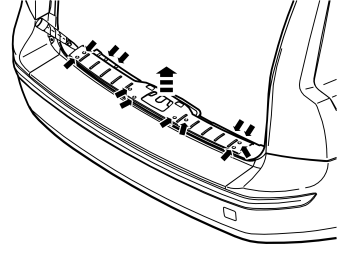
- Prize off the four external clips at the front edge/bottom edge of the sill trim panel on the tailgate.
- Prize up one corner of the sill trim panel using a weatherstrip tool so that the two clips on the short side release. Pull the sill trim panel up so that the remaining six clips release, and remove it.
- Detach the rubber strip where it covers the left and right-hand side panel in the tailgate opening.
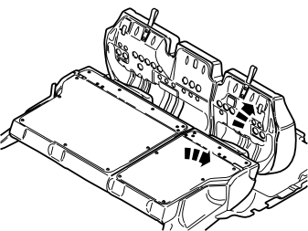
- Fold the seat cushion and backrest forward on both the right and left-hand sides of the rear seat.
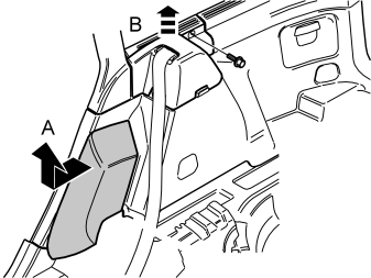
- Grip the top edge of the right-hand side bolster and pull forward so that the clip on the back releases. Move the side bolster upward and remove it.
- Remove the screw at the rear edge of the panel at the front/top of the right-hand side panel.
- Pull the panel upwards so that the four clips on the inside release. Remove the panel.
- Repeat the operation for the left-hand side.
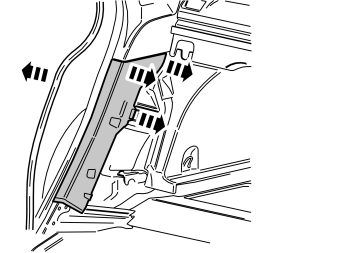
- Pull off the rubber strip at the rear of the opening for the right-hand rear door.
- Carefully prize away the lower C-pillar panel on the right-hand side. Prize at the top edge using a plastic weatherstrip tool. Pull the C-pillar panel in so that the two upper clips release. Then continue downward, until the last two clips have released, and remove the C-pillar panel.
- Repeat the operation for the left-hand side.
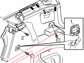
- Fold out the load securing eyelets on the right-hand side panel. Take a scriber with angled tip and insert it in the holes in the top edge of the cover (1). Twist the scriber so that the tip engages the rear side of the cover, and pull the cover away.
- Remove the screws in the load securing eyelets.
- Remove the screw (2) at the front/top edge of the side panel.
- Pull off the side panel at the top so that the two clips at the rear/bottom of the side window and the clip at the bottom of the D-pillar release.
- Disconnect the connector for the 12V socket, if present.
- Lift out the side panel.
- Repeat the operation for the left-hand side.
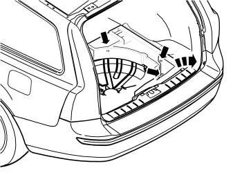
- Remove the right-hand floor support. First remove the three clips in the bottom of the compartments and then lift it up. Do the equivalent on the left-hand side.
Steps 127–134 apply to the S40
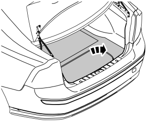
- Remove the cargo compartment carpet.
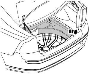
- Remove the upper floor support on the left and right-hand sides if applicable.
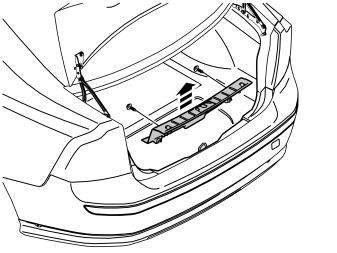
- Unscrew the two external clips at the front edge/bottom edge of the sill trim panel on the tailgate.
- Prize up one corner of the sill trim panel using a weatherstrip tool so that the two clips in the end release. Pull the sill trim panel up at the other end so that the remaining two clips release, and remove it.
- Detach the rubber strip where it covers the left and right-hand side panel in the tailgate opening.
- Fold the seat cushion and backrest on the right-hand side of the rear seat forward.
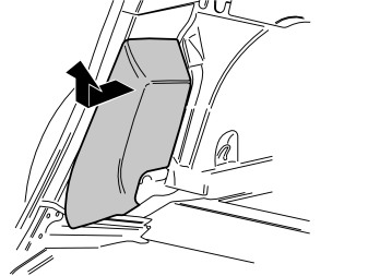
- Grip the top edge of the right-hand side bolster and pull forward so that the clip on the back releases. Move the side bolster upward and remove it.
- Pull off the rubber strip at the rear of the opening for the right-hand rear door.
- Carefully prize away the lower C-pillar panel on the right-hand side. Prize at the top edge using a plastic weatherstrip tool. Pull the C-pillar panel in so that the two upper clips release. Then continue downward, until the last two clips have released, and remove the C-pillar panel.
Illustrations A and B
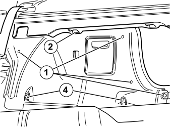
- Remove the five clips (1), in illustrations A and B holding the right-hand side panel in the bodywork.
- Unhook the parcel shelf panel at the front edge at the bracket, (2) in illustration A. Pull the side panel away from the parcel shelf panel and the C-pillar panel.
- Unhook the side panel from the mounting (3), in illustration B, on the underneath of the parcel shelf.
- Disconnect the connector for the 12V socket, if present.
- Unhook the side panel from the load securing eyelets (4), in illustration A. Remove the side panel.
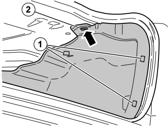
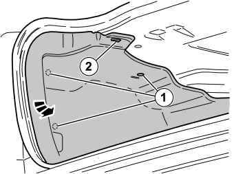
- Remove the three clips (1) holding the left-hand side panel to the body. Unhook the side panel from the bracket (2) on the underside of the parcel shelf.
- Fold out the rear edge of the side panel from the bodywork. At the same time unhook the side panel from the rear load securing eyelet.
- Fold out the side panel so that the amplifier at the rear of the wheel arch is accessible.
Steps 135-137 apply to both the S40 and V50
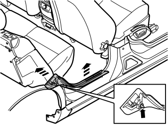
- Pull the top edge of the sill trim panel in the right-hand rear door inwards until the clips on the inside release. Then continue down and pull the panel upwards until the remaining two clips on the underside release.
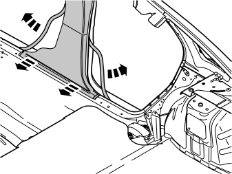
- Pull off the rubber mouldings at the rear edge of the right-hand front door and at the front edge of the right-hand rear door. This releases the lower panel on the B-pillar.
- Pull the bottom edge of the lower panel on the B-pillar until the two bottom clips release.
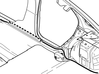
- Route the cable harness with the two grey connectors and the attached thin single cable from the area for the glove compartment. The black/white (SB/W) single cable is plugged into the connector in step 87, and must be routed along as far as possible.
- Route the cables inside the floor carpets, the lower B-pillar panel and the insulation panels, back toward the amplifier in the left-hand rear wheel arch. Route the cables along the existing cable harnesses in the cargo compartment.
Осторожно: Ensure that the cable is positioned so that there is no risk of it catching or rubbing.
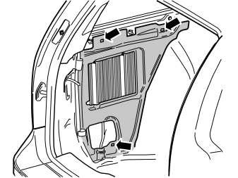
Applies to the V50
- Remove the insulation panel around the existing amplifier. First remove the three clips.
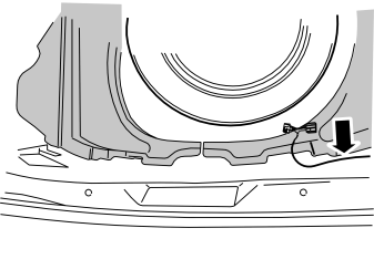
Applies to the S40 and V50
- Continue to route the cable harness with the two grey connectors.
- Position the cable harness as illustrated.
- Clamp in the cable harness at the existing cable harness using three tie straps.
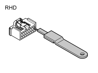
Applies to right-hand drive cars
- Take the adapter cable, P/N 30752743, with two large green and two grey connectors from the kit.
- Remove the connector's secondary catch on the male connector in accordance with step 107.
- Remove the cables from position 1, grey/red (GR/R), and position 3, yellow/red (Y/R). Carefully insert the tool, P/N 9512639 as illustrated, detach the primary catch and at the same time pull out the cables.
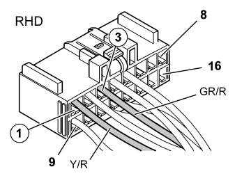
Applies to right-hand drive cars
- Change places on both cables so that the positions are as illustrated.
- Reinstall the secondary catch.
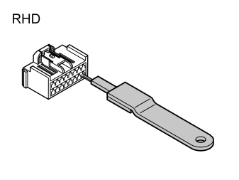
Applies to right-hand drive cars
- Remove the cables from position 9, grey (GR), and position 11, yellow (Y). Carefully insert the tool, P/N 9512639 as illustrated, detach the primary catch and at the same time pull out the cables.
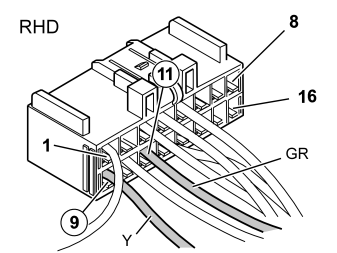
Applies to right-hand drive cars
- Change places on both cables so that the positions are as illustrated.
- Reinstall the secondary catch.
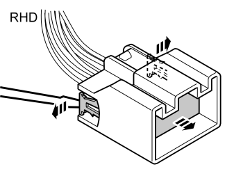
Applies to right-hand drive cars
- Remove the secondary catch on the large green female connector. Carefully prize out the catches at the sides and move them forward. Pull out the catch.
- Now change positions on the same cables in the connector, as those in the steps above for the male connector (1-3, 9-11).
- Reinstall the secondary catch.
Applies to all models
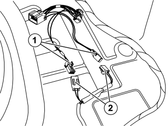
- Plug the small grey connectors (1) into the adapter cable, P/N 30752743, to the corresponding grey ones (2) in the routed cable harness.
- Route the cable harness with the T-cable to the amplifier on the left-hand side.
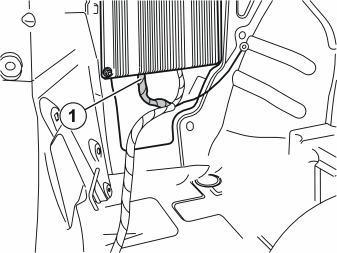
- Remove the rear connector (1) on the amplifier.
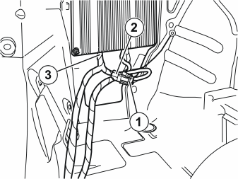
- Connect the T-cable to the amplifier as follows:
Installing the screen
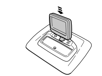
- Take the screen from the kit and press it in on the connector/holder.
Installing the remote control holder
Illustration A
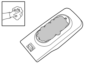
- Clean the rear side of the holder for the remote control using isopropanol. Wipe dry.
Illustration B
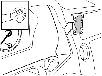
- Clean the front of the bracket using isopropanol. Wipe dry.
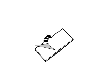
- Take double-sided adhesive tape from the kit and remove one piece of protective backing tape.
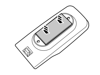
- Firmly press the tape in on the rear side of the holder.
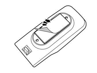
- Remove the remaining protective backing tape from the double-sided adhesive tape.
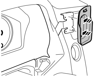
- Firmly press the holder in on the bracket.
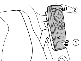
- Secure the remote control from the kit into the holder.
Finishing work
Cargo compartment
- Reinstall the insulation panel on the left-hand side (applies to V50).
- Reinstall the floor supports (applies to V50).
- Reinstall the side panels (S40/V50) with cover panels (V50).
- Torque tighten the screws in the load securing eyelets to 24 Nm (18 lbf.ft.) (V50).
- Reinstall the tailgate sill trim panel.
- Reinstall the upper floor support if applicable (applies to the S40).
- Reinstall the rubber strips in the tailgate opening.
- Reinstall the cargo compartment carpet.
Passenger compartment
- Reinstall the B and C-pillar panels on the right-hand side.
- Fold the floor carpet back at the right-hand front seat.
- Reinstall the passenger compartment connector socket, if applicable.
- Reinstall the sill trim panels on the right-hand side.
- Reinstall the rubber strips in the door openings on the right-hand side.
- Reinstall the side bolster.
- Position the backrest and seat cushions back into place.
Dashboard
- Reinstall the lower vent.
- Plug in the connectors to the lighting for the front section of the glove compartment. Tighten in the glove compartment.
- Reinstall the clip in the air vent on the end face of the dashboard.
- Reinstall the end face panel on the end face of the dashboard.
- Reinstall the centre console and connect the dashboard environment panel.
- Reinstall the panel in the rear edge of the centre console.
- Connect and reinstall the display unit.
- Press the surround for the display into place.
- Reinstall the panel inside the centre console.
- Reconnect the battery negative lead.
Programming the system
Illustration A
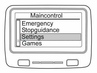
Program the system as follows:
- Select "Settings"
- Select "Service"
- Press OK at "Code"
- Enter code:
- Select "X-Code"
- Enter code:
- Press "OK"
- Press "Save settings"
Примечание: Do not forget this!
Illustration B
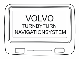
Volvo menu
- The system now starts up with the Volvo logo and is ready for use.
Radio Mute function
Applies only if the car has AEM and the Radio Mute function is desired
The function mutes the radio when there are navigation messages.
- Take a new cable with minimum area 0.35 mm² (0.000542501 in²).
- Using a crimping sleeve, splice the new cable with the brown/white (BN/W) cable from the brown connector at the navigation unit.
- Route the cable along the rear crossmember and connect it at position 11 in the AEM. If the position is in use by handsfree mute, splice the cable with the crimping sleeve. Make sure that the splices are performed as described in steps 113 - 115.
- Load the Telemute application in AEM.