Примечание: - Points 20 - 32 only apply to the S40 (04-)
- Points 33 - 40 only apply to the V50
- Points 45 - 50 only apply to the V50
- Point 51 only applies to the S40 (04-)
Примечание: This accessory requires software unique to the car.
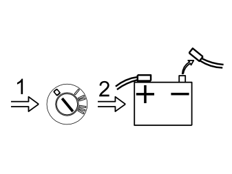
- Turn the ignition switch to position 0.
- Disconnect the battery negative lead.
Примечание: Wait at least five minutes before disassembling the connectors or removing other electrical equipment.
Illustration A
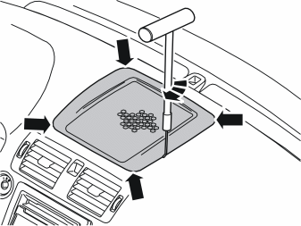
- Remove the loudspeaker grille as follows: Insert tool P/N 999-5919-46 into the joint between the loudspeaker grille and the dashboard as illustrated, until it engages.
- Twist the tool 90° so that the bent section engages with the underneath of the loudspeaker grille.
Illustration B
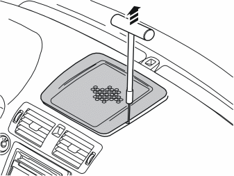
- Pull upwards until the loudspeaker grille detaches. The loudspeaker grille is securely fastened by four clips. Move the tool closer to the clip to facilitate removal.
Примечание: Do not damage the dashboard.
- Place the loudspeaker grille to one side. The loudspeaker grille will not be used again.
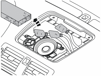
- Remove the foamed plastic located above the foam covered connectors.
- Remove the foam covers from the connectors. Not all cars have centre loudspeakers, the illustration shows where a centre loudspeaker is fitted.
Installing the screen
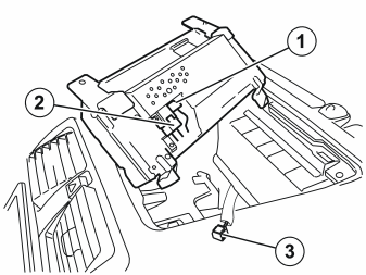
- Connect the pre-routed blue connector (1) and the pre-routed DIN cable (2) (in the cut-out in the dashboard) to the screen from the kit.
Примечание: Pull the cable with the green connector (3) so that it comes out in front of the screen.
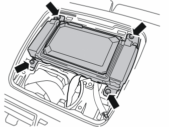
- Tighten the screen. Use the four screws from the kit.
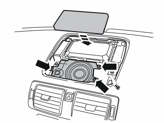
- Carefully press the panel into place over the rear of the screen.
Installing the IR sensor
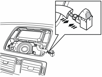
- Take the IR sensor from the kit.
- Plug the sensor into the green connector pulled out earlier.
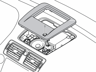
- Take the new grille from the kit.
- Fit the IR sensor so that the connector points forward and so that the sensor surface points in towards the passenger compartment.
- Press the sensor into the grille's hooks.
- Press the grille into the hole so that all hooks engage.
Installing the DVD reader
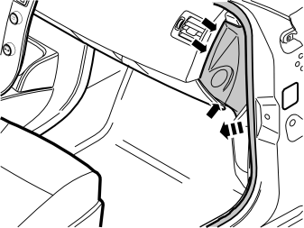
- Remove the panel on the right-hand end of the dashboard. Carefully pry off the panel using a weatherstrip tool. Pry all around until the three clips release.
Примечание: Do not damage the dashboard.
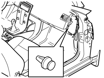
- Remove the clip which holds the vent for the air duct.
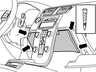
- Open the glove compartment and remove any contents.
- Carefully pry off the panel inside the centre console. Use a plastic weatherstrip tool. The panel is secured by two clips on each of the short sides.
- Pull the panel downwards.
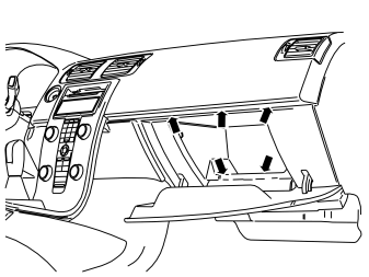
- Remove the five screws in the opening for the glove compartment.
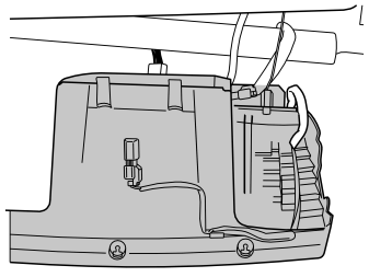
- Remove the front section of the glove compartment. Pull it backwards until the two clips on the upper edge release. Then release the two connectors on the upper side.
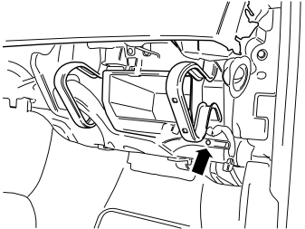
- Remove the screw to the air vent on the right-hand side. Pull it away from the connection and lay it aside.
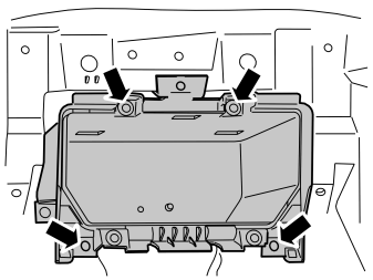
- Undo the screws securing the glove compartment inner section.
- Pull out the glove compartment and put it to one side.
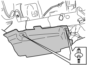
- Remove the soundproofing panel on the right-hand side by first pressing in the centre of the clips and then pulling the panel away with the clips.
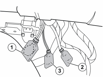
- Fold aside the floor carpet on the right-hand side, under the impact member, in order to access the foam covered connectors taped at the existing cable harness.
- Remove the cables from the tape and remove the foam covers (2) and (3).
- Remove the MOST loop located on the fibre optic cables (1).
- Illustration 17 shows the connectors with foam covers and the MOST loop.
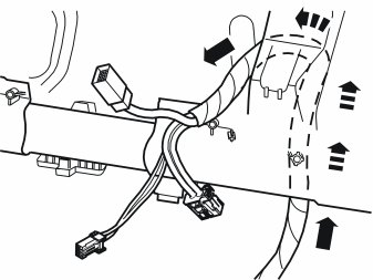
- Carefully pull the cables up over the impact member and make sure that the fibre optic cables are not bent to a radius of less than 25 mm (1").
Illustration A
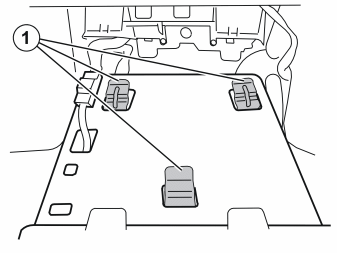
- Take the DVD reader from the kit.
- Fit the DVD reader in the inner section of the glove compartment with the hooks (1).
- Lift up the DVD and the glove compartment so that the cables routed to the sockets on the rear of the DVD reader can be connected.
Illustration B
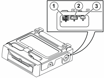
- Connect the wiring to the reverse of the DVD reader:
Примечание: Ensure that the cable harness is not pinched on the reverse of the DVD reader The fibre optic cables are easily damaged and must not be bent to a radius of less than 25 mm (1").
Illustration C
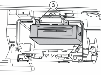
- Fit the inner section of the glove compartment in its correct position.
- Use the screws (3) which were previously removed and screw in both the DVD reader bracket and the glove compartment.
- Refit the soundproofing panel and secure it using the clips which were previously removed.
- Connect the connectors to the front section of the glove compartment.
- Reinstall the front section of the glove compartment.
- Reinstall the panel inside the centre console.
- Reinstall the clip for the air vent.
- Reinstall the panel on the right-hand end of the dashboard.
Applies to the S40 (04-), European market only.
Installing the traffic message channel module (TMC)
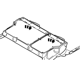
- Fold the rear backrests forward.
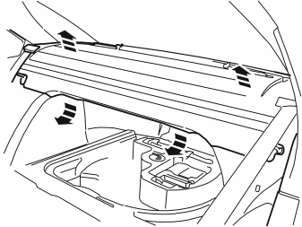
- Remove the parcel shelf panel. First remove the parcel shelf panel from the two mountings on the left and the right of the underside. Pull the panel upwards at the front edge until the two clips on the underside release and the two guide pins have come out of their holes.
- Pull out the parcel shelf. Lay the parcel shelf on the folded backrests.
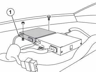
- Remove the TMC cable fitted with paper tape on the cargo compartment lighting cables.
- Remove the cover for the connector to the fibre optic cable in the traffic message channel module (TMC).
- Take the traffic message channel module (TMC), the screw and the nut from the kit. Tighten the existing stud and welded nut at the rear edge of the parcel shelf.
- Connect the pre-routed 1-pin connector (1) to the traffic message channel module (TMC).
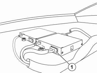
- Disconnect the fibre optic cable (1) from the AM/FM tuner module (AFM).
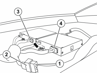
- Connect the T-fibre optic cable from the kit to the control modules as follows:
Примечание: Do not damage the fibre optic cables. The fibre optic cables must have a radius of at least 25 mm (1 ”).
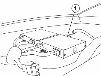
- Disconnect the antenna cable (1) from the AM/FM tuner module (AFM).
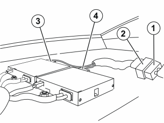
- Connect the T-fibre optic cable from the kit between the control modules as follows:
- Reinstall the parcel shelf panel.
- Fold the backrest back into place.
Cargo compartment preparations
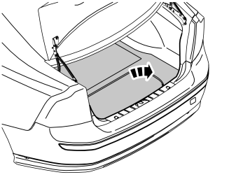
- Remove the cargo compartment carpet.
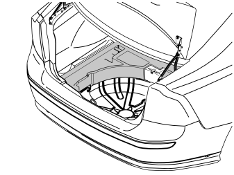
- Remove the upper floor supports on the left and right-hand sides if applicable.
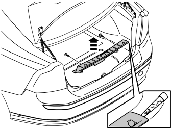
- Unscrew the two external clips at the front edge/bottom edge of the sill trim panel on the tailgate.
- Pry up one of the corners of the sill trim panel using a weatherstrip tool so that the two clips at that end release.
- Pull up the sill trim panel at the other end so that the remaining two clips release. Remove the sill trim panel.
- Detach the rubber strip where it covers the left-hand side panel in the boot opening.
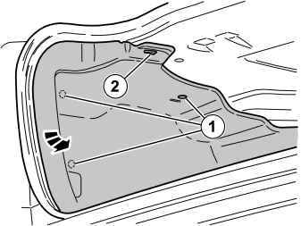
- Remove the three clips (1) securing the left-hand side panel in the bodywork.
- Unhook the side panel from the mounting (2) on the underneath of the parcel shelf.
- Fold out the rear edge of the side panel from the bodywork. At the same time unhook the side panel from the rear load securing eyelet.
- Fold out the side panel so that the amplifier at the rear of the wheel arch is accessible.
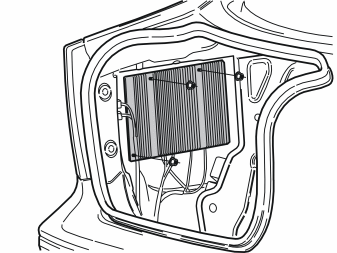
- Remove the three nuts holding the amplifier to the body.
- Remove the amplifier. Disconnect the front connector from the fibre optic cables.
Applies to the V50
Cargo compartment preparations
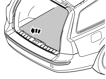
- Remove the cargo compartment carpet.
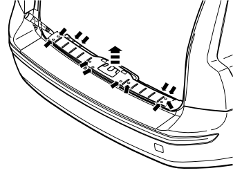
- Pry off the four external clips at the front edge/bottom edge of the sill trim panel on the tailgate.
- Pry up one of the corners of the sill trim panel using a weatherstrip tool so that the two clips at that end release.
- Pull up the sill trim panel so the remaining six clips release. Remove the panel.
- Detach the rubber strip where it covers the left-hand side panel in the boot opening.
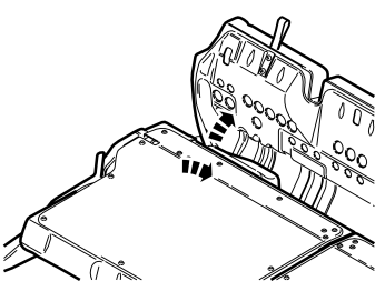
- Fold the seat cushion and backrest on the right-hand side of the rear seat forward.
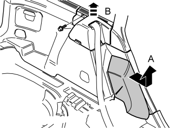
- Grasp the upper edge of the left-hand side cushion (A). Pull the side cushion forward so that the clip on the reverse releases.
- Slide the side cushion upwards.
- Remove the screw at the rear edge of the panel (B) at the front/top of the left-hand side panel.
- Pull the panel upwards so that the four clips on the inside release.
- Repeat the operation on the other side.
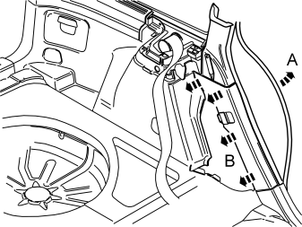
- Pull off the rubber strip (A) at the rear of the opening for the left-hand rear door.
- Carefully pry off the lower panel (B) on the C-post at the top edge. Use a weatherstrip tool.
- Pull the C-post panel downwards until all four clips have released.
- Repeat the operation on the right-hand side.
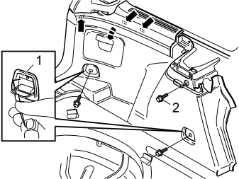
- Fold out the load securing eyelets on the left-hand side panel.
- Insert a scriber with an angled tip into the holes in the top of the covers (1). Turn the scriber so that the tip engages the reverse of the cover. Pull the cover off.
- Remove the two screws from the load securing eyelets.
- Remove the screw (2) at the front/top edge of the side panel.
- Pull off the side panel at the top so that the two clips at the rear/bottom of the side window and the clip at the bottom of the D-post release.
- Lift out the side panel.
- Remove the right-hand side panel in the same way. If the car has a 12 V socket in the right-hand side panel, disconnect the connector from this socket.
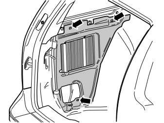
- Remove the insulation panel around the amplifier on the left-hand side. First remove the three clips.
- Remove the insulation panel on the right-hand side in the same way.
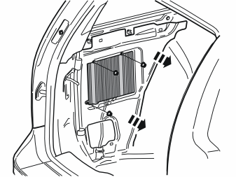
- Remove the three nuts holding the amplifier to the body.
- Remove the amplifier. Disconnect the front connector from the fibre optic cables.
Applies to the S40 (04-) and V50
Installing the global positioning system module (GPS)
Illustration A
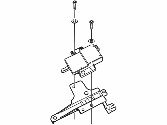
GPS module preparations
- Take the GPS module, bracket, screws and washers from the kit.
- Position the GPS module on the bracket so that the screw holes correspond with the thread inserts in the bracket.
- Fit the screws and washers and tighten manually.
- The GPS power cable and the GPS antenna cable are secured under the AUD. The GPS antenna cable is located in a hole on the flange under the AUD and the GPS power cable is secured with paper tape at the wiring harness up to the AUD. These cables must be released from the tape and clips before use.
Illustration B
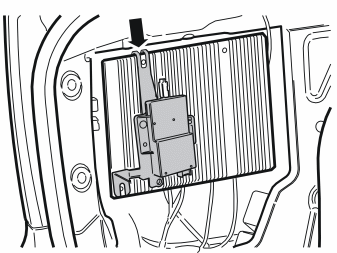
- Remove the cover for the connector to the fibre optic cable in the global positioning system module (GPS).
- Hook in and snap the control module into place at the top edge and opposite the rear mounting hole in the amplifier.
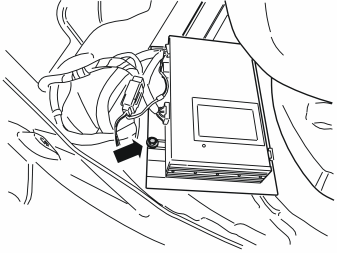
- Turn the amplifier. Tighten the lower mounting from the control module using a screw from the kit.
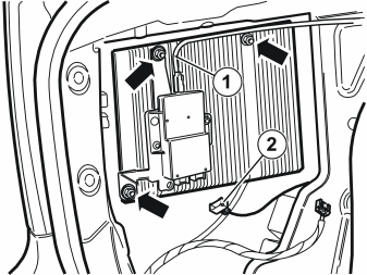
- Reinstall the amplifier on the studs.
- Install and tighten the three nuts. Tighten to 10 Nm (7.5 lbf. ft.).
- Connect the pre-routed antenna cable (1) to the control module.
- Connect the pre-routed 5-pin connector (2) for the power supply to the control module.
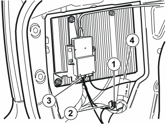
- Connect the T-fibre optic cable from the kit between the global positioning system module (GPS) and amplifier. Connect as follows:
Примечание: Do not damage the fibre optic cables. The fibre optic cables must have a radius of at least 25 mm (1 ”).
Applies to the V50, European market only.
Installing the traffic message channel module (TMC)
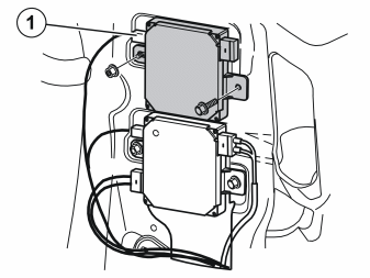
- Remove the TMC cable fitted with paper tape from the cable running to the tank lock motor.
- Remove the cover for the connector to the fibre optic cable in the traffic message channel module (TMC).
- Take the traffic message channel module (TMC), the screw and the nut from the kit. Tighten the existing stud and welded nut at the rear edge of the right rear wheel well.
- Connect the pre-routed 1-pin connector (1) to the traffic message channel module (TMC).
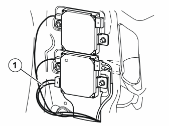
- Disconnect the fibre optic cable (1) from the AM/FM tuner module (AFM).
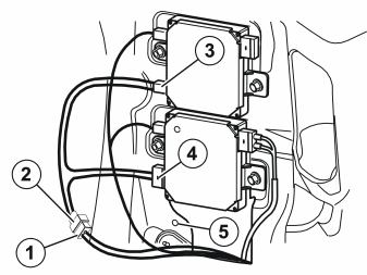
- Connect the T-fibre optic cable from the kit to the control modules as follows:
- Press connectors (1) and (2) into place in the hole (5), and the clips on the female contact of the T-fibre optic cable.
Примечание: Do not damage the fibre optic cables. The fibre optic cables must have a radius of at least 25 mm (1 ”).
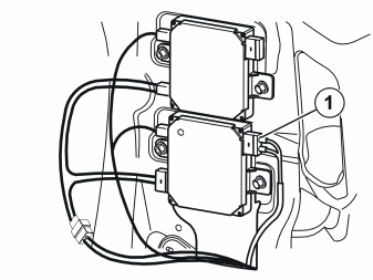
- Disconnect the antenna cable (1) from the AM/FM tuner module (AFM).
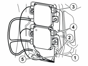
- Connect the T-fibre optic cable from the kit between the control modules as follows:
- Press connectors (1) and (2) into place in the hole (5), and the clips on the female contact of the T-antenna cable.
- Reinstall the insulation panels on the right and left-hand sides.
- Reinstall the side panels. If the car has a 12 V socket, connect the connector to this.
- Tighten the screws for the load securing eyelets. Tighten to 24 Nm (18 lbf. ft.).
- Reinstall the panel at the front/top of the side panel. Press downwards so that the catches engage. Tighten using the screw.
- Reinstall the C-post panels.
- Reinstall the side cushions.
- Reinstall the rubber strips in the door openings.
- Fold the backrests and the seat cushions back into place.
- Reinstall the rubber strip in the boot lid opening.
- Reinstall the sill trim panel in the boot opening.
- Reinstall the cargo compartment carpet.
- Reconnect the battery negative lead.
- Program the software according to the service information in VIDA.
Applies to the S40 (04-)
- Reinstall the side panel.
- Reinstall the rubber strip in the boot lid opening.
- Reinstall the sill trim panel in the boot opening.
- Reinstall the upper floor supports if applicable.
- Reinstall the cargo compartment carpet.
- Reconnect the battery negative lead.
- Program the software according to the service information in VIDA.
Обсуждение и оценка
0Пока нет комментариев. Будьте первым.