Примечание: This accessory requires software unique to the car.
Примечание: TMC unit, P/N 6849907, is available as a separate purchase in Europe.
Preparations
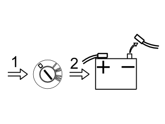
- Position the driver's seat in the rearmost position
- Turn the ignition key to position 0
- Disconnect the battery negative lead.
Примечание: Wait at least five minutes before disassembling the connectors or removing other electrical equipment.
Illustration A
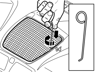
Remove the loudspeaker grille as follows:
- Take a piece of 1.5 mm (1/16”) diameter welding rod. Bend one end to 90° (L=5 mm (13/64”)). The other end is bent to form a handle
- Insert the first bent end down into the joint between the loudspeaker grille and the dashboard as illustrated, until it engages
- Twist the welding rod 90° so that the bent section engages with the underneath of the loudspeaker grille. It may be necessary to move the welding rod along the joint to twist the rod around.
Illustration B
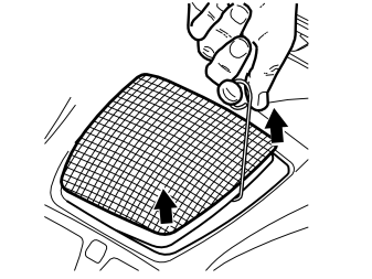
- Pull upwards until the loudspeaker grille detaches. The loudspeaker grille is securely fastened by four clips.
Примечание: Do not damage the dashboard.
- Place the loudspeaker grille to one side.
Illustration C
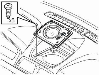
Applies to cars without a centrally mounted loudspeaker
- Remove the bracket for the loudspeaker grille by removing the five screws and pulling it up out of the dashboard.
Illustration D
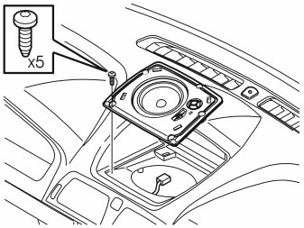
Applies to cars with a centrally mounted loudspeaker
- Remove the five screws in the loudspeaker. Pull up the loudspeaker slightly from the dashboard. Disconnect the connector.
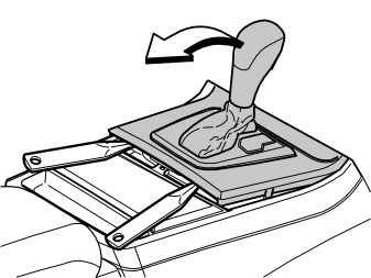
Applies to cars with automatic gearboxes
- Turn the ignition key to position II.
Applies to all models
- Move the gear selector lever to its rearmost position
- Carefully pry off the gear selector lever panel at the lower edge using a weatherstrip tool. Pull the panel backwards to access the screws for the dashboard environment panel.
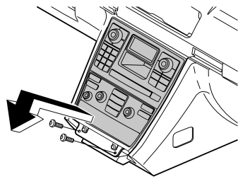
- Remove the screws holding the bracket for the dashboard environment panel and the control module
- Pull out the bracket at the lower edge. Pull downwards from the top edge of the centre console
- Disconnect the connectors from the dashboard environment panel, control module. If applicable disconnect the CD player and/or Mini disc player connectors.
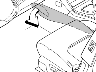
- Remove the left-hand side panel from the transmission tunnel. Pull off the panel starting at the front edge. Then pull backwards until all the clips release.
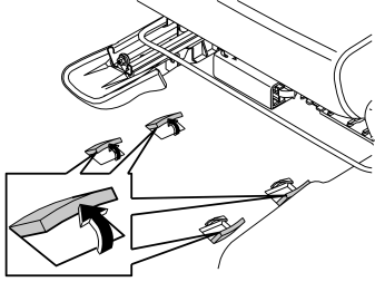
- Fold up the four perforated carpet tabs under the left-hand front seat.
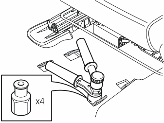
- Install the four rivet nuts from the kit in the pre-punched holes under the carpet tabs
- Use rivet tool (Volvo P/N 9512782) to tighten the rivet nuts. If necessary: Remove the mounting bracket for the seat front-rear adjustment (applies to cars with manual seats).
Installing the cable harnesses
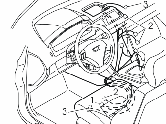
- Take the two cable harnesses (the fibre optic harness (1) with the cable harness for power supply (2), and the cable harness for the display (3)) from the kit. Pull them up along the air duct on the left-hand side of the centre console.
Примечание: Do not damage the fibre optic cables. They must not be bent in a radius less than 30 mm (1 11/64”) or they may be damaged and disrupt the function of the DVD reader.
- The fibre optic harness (1) with the cable harness for power supply (2) is positioned inside the centre console. The blue connector in the cable harness (2) and (3) must be routed up to the outlet in the dashboard
- Route the cable harnesses backwards inside the carpet on the left-hand side of the transmission tunnel, under the right-hand seat rail for the left seat, and out of the carpet join under the seat.
Installing and connecting the display screen
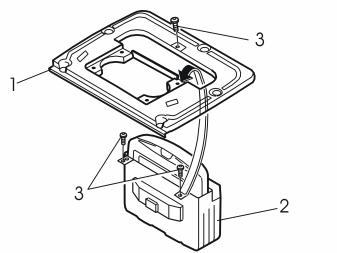
Applies to cars without a centrally mounted loudspeaker
- Install the bracket (1) on the display (2). Use the screws (3) (from the kit).
Applies to cars with a centrally mounted loudspeaker
- Install the bracket (1) on the display screen (2). Use the front screw (3).
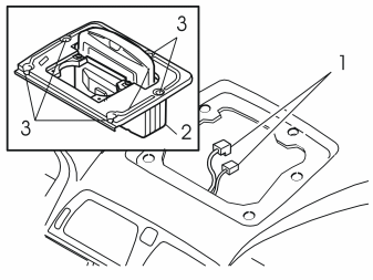
Applies to cars without a centrally mounted loudspeaker
- Connect the wiring for the DVD reader (1) to the display (2)
- Install the display screen and the bracket in the dashboard. Use the existing screws (3)
- Press the new loudspeaker grille (from the kit) into place on the dashboard.
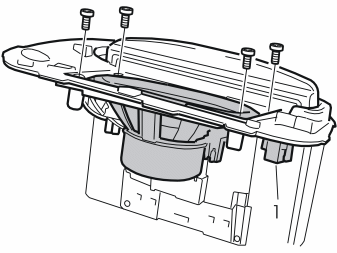
Applies to cars with a centrally mounted loudspeaker
- Install the centrally mounted loudspeaker in the cut out in the bracket for the display screen
- Tighten the loudspeaker into place. Use the four screws
- Press the connector (1) for the centre loudspeaker into the bracket on the left-hand under side of the display screen bracket.
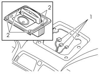
Applies to cars with a centrally mounted loudspeaker
- Connect the three cables (1) to the display screen and the centrally mounted loudspeaker
- Press the display screen and bracket into the dashboard. Tighten using the five existing screws (2)
- Press the new loudspeaker grille (from the kit) into place on the dashboard.
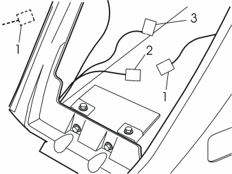
Applies to cars without a MiniDisc player or CD player/changer
- Locate the pre-routed 4-pin grey connector for power supply (1). It is either taped to the thick cable harness under the steering rack (first detach the soundproofing above the pedals, it is secured with two screws and two clips), or it is taped to the thick cable harness in the centre console
- Connect the grey connector (2) from the cable harness for power supply to the pre-routed connector
- Clamp the excess connector (3) in position.
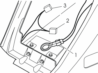
Applies to cars without a MiniDisc player or CD player/changer
- Find the park connector (1) for the fibre optic cables which is secured on the inside of the centre console
- Remove the park connector and connect the connector (2) on the fibre optic cables that were routed earlier
- Connect the park connector to the excess connector (3) on the routed fibre optic cables.
Connecting to the MiniDisc player or CD player/changer
Примечание: Illustrations en-GB0900c8af800dd915#KC01343157 - en-GB0900c8af800dd915#KC01343165 show a car with both a MiniDisc player and a CD player/changer, and show the cable routing and connection to the MiniDisc player. If the car only has a CD player/changer, the cable routing and connection is carried out a in the same way.
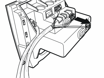
Applies to cars with a MiniDisc player or CD player/changer
- Press in the catches on top and remove the connector from the MiniDisc player/CD player/changer.
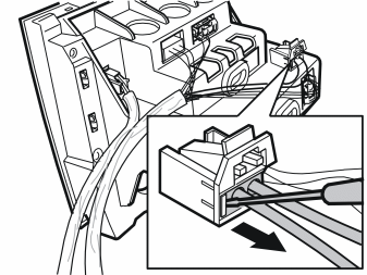
Applies to cars with a MiniDisc player or CD player/changer
- Press in the catch on the side of the connector removed from the MiniDisc player/CD player/changer. Pull off the small connector and the fibre optic cables.
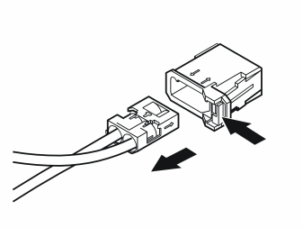
Applies to cars with a MiniDisc player or CD player/changer
- Press in the catch on the side of the male connector on the routed fibre optic cable harness. Pull off the small connector and the two fibre optic cables from the connector sleeve
- Locate the loose connector sleeve.
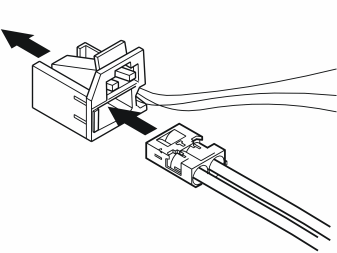
Applies to cars with a MiniDisc player or CD player/changer
- Take the small connector with the two fibre optic cables removed from the routed fibre optic cable harness. Connect it to the large connector for the MiniDisc player/CD player/changer
- Reinstall the connector in the MiniDisc player/CD player/changer.
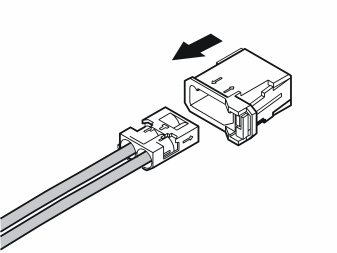
Applies to cars with a MiniDisc player or CD player/changer
- Take the remaining fibre optic with the small connector and press it into the previously unused connector sleeve.
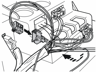
Applies to cars with a MiniDisc player or CD player/changer
- Route the cables from the two remaining connectors under the existing cable harness. Connect both the connectors to each other.
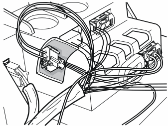
Applies to cars with a MiniDisc player or CD player/changer
- Take a piece of foam tape from the connector and wind it around the connector for the fibre optic cables to prevent rattle.
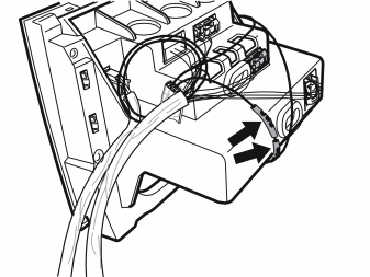
Applies to cars with a MiniDisc player or CD player/changer
- Take the kink protector out of the kit and press it on to the fibre optic cables as illustrated. The kink protector ensures that the fibre optic isn't bent too much and protects it to ensure that function is not disrupted.
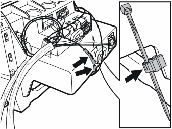
- Take the tie strap and the clip from the kit. Press the clip into place on the left edge of the bracket as shown in the small illustration. Position it so that it is turned in towards the centre of the bracket
- Clamp both the loose fibre optic cables into place.
The wiring must be positioned in this way on the reverse of the bracket when the bracket and MiniDisc player and/or CD player/changer are reinstalled in the centre console.
- Reinstall the bracket with the MiniDisc player or CD player/changer in the centre console. At the same time check that all cables are correctly routed.
Connecting and installing the DVD reader
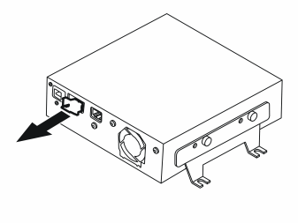
- Take the DVD reader from the kit. Remove the protective plugs from the connector for the fibre optic cable connection.
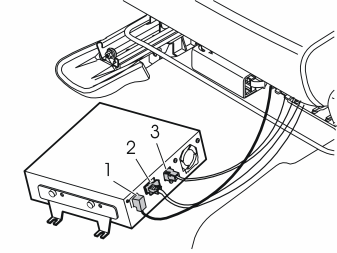
Connect the routed cables to the DVD reader:
- the cable (1) for the display screen
- the cable (2) to the fibre optic wiring system in the car
- the power supply cable (3).
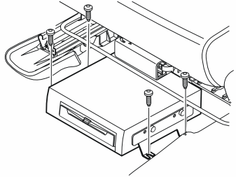
- Take four screws from the kit. Position the mounting brackets for the DVD reader over the rivet nuts and tighten the unit
- Hide the wiring under the carpet on the reverse of the DVD reader
- Fold the carpet tabs back over the screws.
Примечание: Do not damage the fibre optic cables. They must not be bent in a radius less than 30 mm (1 11/64”) or they may be damaged and disrupt the function of the DVD reader.
- Reinstall the left-hand side panel on the centre console
- Connect the connectors to the dashboard environment panel. If applicable connect the CD player and/or Mini disc player connectors
- Position the bracket. Tighten the bracket using the two screws. Reinstall the gear selector lever panel.
Installing the GPS aerial and TMC unit (Europe)
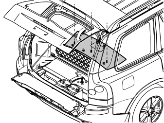
- Remove the cover and the screws for the rear headlining
- Carefully pry off the panel at the rear edge using a weatherstrip tool
- Pull the rear edge of the panel downwards until all clips in the inside have released
- Disconnect the connector for the rear roof lighting. Pull the panel backwards.
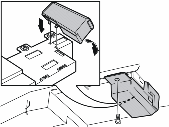
- Take the GPS aerial and screw from the kit. Insert the two locating pins down one length of the GPS aerial into the corresponding holes in the aerial module
- Fold the GPS aerial down towards the aerial module (ATM) so that the clip and connector on the bottom of the GPS aerial engage in the corresponding hole and connector in the aerial module (ATM)
- Tighten the GPS aerial using the screw.
TMC unit, P/N 6849907, is available as a separate purchase in Europe.
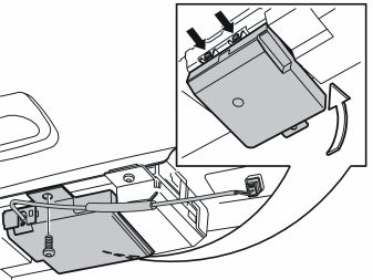
Applies to European users
- Take the TMC unit and the screw from the kit. Insert the two locating pins down one side of the TMC unit into the corresponding holes in the aerial module (ATM)
- Fold the TMC unit down towards the aerial module (ATM) so that the clip and connector on the bottom of the TMC unit engage in the corresponding hole and connector in the aerial module (ATM)
- Tighten the TMC unit using the screw.
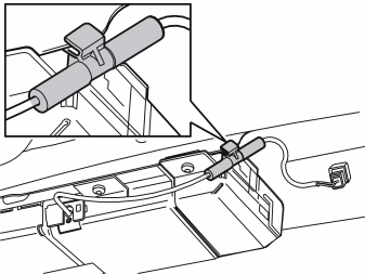
Applies to European users
- Secure the clip on the cable for the TMC unit using tape from the kit
- Press the cable for the TMC unit into place on the edge of the panel using clips as illustrated
- Reinstall the rear headlining.
Installing the keypad in the steering wheel
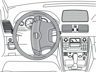
- Turn the steering wheel 90º to the position illustrated, so that the two holes on the reverse of the steering wheel are accessible.
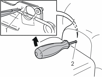
- Insert a screwdriver in the hole on the reverse of the steering wheel, at right angles to the rear surface of the steering wheel
- Insert a screwdriver as far as possible to determine the position of the end of the spring clip (1)
- Position the end of the screwdriver on top of the spring clip
- Pry the screwdriver upwards towards the upper edge of the hole (2) until the spring releases and one side of the steering wheel module springs out and releases from the mounting
- Turn the steering wheel 180º. Carry out the procedure on the other side
- Turn the steering wheel to the neutral position.
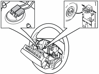
- Fold the steering wheel module out
- Remove the two connectors (1) for the sender wiring on the airbag.
Примечание: The connectors are tightly secured. However, tools must not be used when removing.
- Place the steering wheel module to one side.
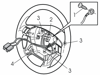
Remove:
- the screw (1). Remove the ground lead
- the connector (2) for the horn and the keypads
- the three screws (3). Lift out the horn (4).
Illustration A
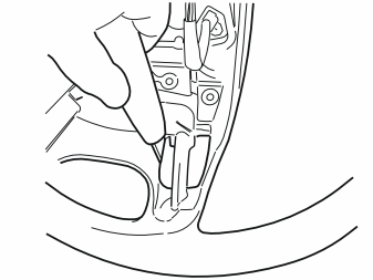
- Place the steering wheel in a suitable position and cut using a small knife following the existing markings.
Примечание: Ensure that the knife is held so that cutting is carried out at right angles to the reverse of the steering wheel. This is to reduce the risk of cutting a large hole as the edge around the keypad is only a few millimetres wider than the keypad itself.
Illustration B
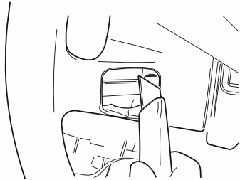
- Also cut off a section of material on the reverse of the steering wheel spoke
- Cut until the keypad is positioned properly.
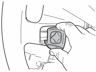
- Take the keypad, two screws and the cover from the kit
- Ensure that the cable is positioned underneath the steering wheel spoke
- Insert the keypad in the hole in the steering wheel with the text on the buttons facing upwards. Press inwards until the keypad lies flush with the steering wheel cover.
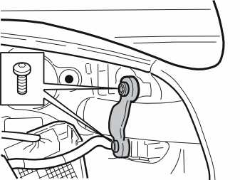
- Tighten the keypad and cover around the spoke. Use the screws.
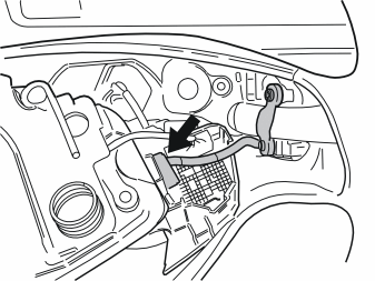
- Position the horn as illustrated
- Connect the installed keypad connector to the reverse of the keypad on the right-hand side of the horn. The cable from the installed keypad is extremely short and the connector is difficult to connect.
- Reinstall the horn. Ensure that the three springs are correctly positioned. Check that the ground lead is not trapped
- Tighten the screws diagonally. Tighten to 6.5 Nm (5 lbf. ft)
- Reinstall the ground lead. Tighten the ground lead
- Connect the connector for the horn and the keypads
- Check the function of the horn. Press the horn all the way around its circumference.
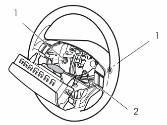
- Check that the two springs (1) are in position
- Press the two connectors for the sender cables for the airbag into the steering wheel module.
Примечание: The wiring must be routed through the existing holder (2).
- Insert the two pins on the reverse of the steering wheel module in the two springs. Ensure that the sender cables are unimpeded
- Press the steering wheel module into the mountings. Two clicks should be heard.
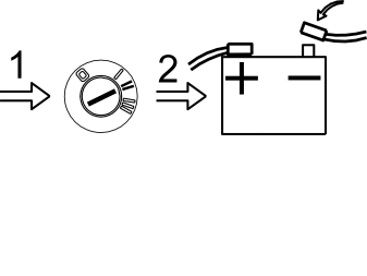
- Turn the ignition key to position II
- Connect the battery negative lead
- Program the software. See the service information in VIDA
- Run “Read and erasing diagnostic trouble codes (DTCs) aerial module (ATM)” according to VIDA vehicle communication after the software has been downloaded.
Обсуждение и оценка
0Пока нет комментариев. Будьте первым.