Применимость
| Модель | Двигатель | Год |
|---|---|---|
| S40 (04-) | — | 2004–2012 |
| V50 | — | 2004–2012 |
Внимание: Take care when working with tensioned springs. Follow the instructions carefully to avoid personal injury.
Installing the front lowering kit
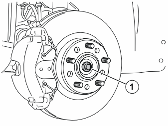
- Raise the car
- Remove the front wheel
- Remove the screw (1)
- Press the drive shaft in a little.
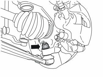
- Remove the nut for the ball joint on the stub axle.
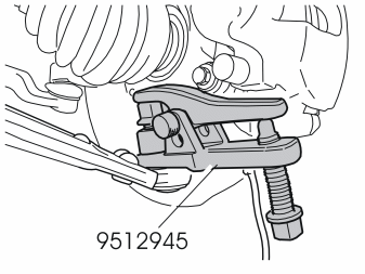
- Remove the ball joint from the control arm. Use tool (P/N 9512945).
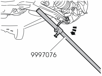
- Pull the ball joint out of the stub axle. Use tool (P/N 9997076).
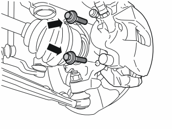
- Remove the brake hose from the bracket on the spring strut
- Remove the two screws for the brake calliper. Hang the calliper up so that the brake hose cannot be damaged.
- Pull out the drive shaft from the hub. Hang up the drive shaft
- Hang the stub axle up on the ball joint. Loosely install the nut. Use tool (P/N 9997076).
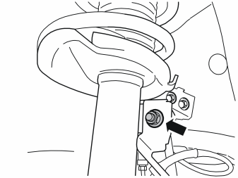
Remove:
- the nut for the anti-roll bar link
- the bracket for the ABS sensor
- the anti-roll bar link.
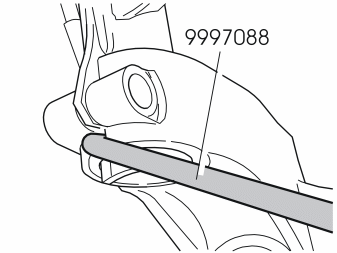
- Remove the screw from the stub axle
- Widen the groove in the stub axle. Use tool (P/N 9997088). Insert the tool with the flat sides lengthways in the groove. Turn the tool 45°.
- Carefully tap the stub axle down using a copper mallet. Bend down the control arm using tool (P/N 9997076) until the spindle releases from the spring strut.
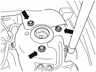
Remove:
- the three screws
- the spring strut.
Illustration A
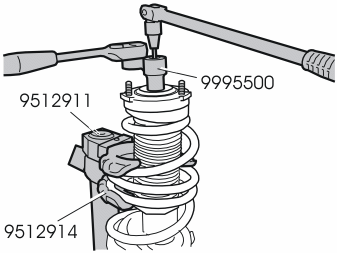
- Relieve the load on the spring seat. Use hydraulic tool (P/N 9992911) together with claws (P/N 9992914).
Remove:
- the nut on the shock absorber. Use socket (P/N 9995500) and a Torx socket as a counterhold
- the spring seat
- the rubber bump stop together with the boot
- the spring.
Примечание: Note the position of the spring to facilitate the installation of the new spring.
Illustration B
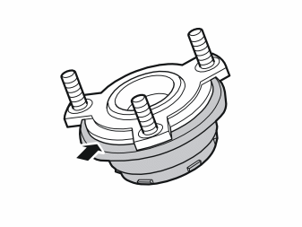
Примечание: Ensure that the spring seat and the shock absorber bearing do not separate. The bearing comprises loose balls in a frame which will fall out in the event of separation.
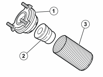
- Check the shock absorber bearing/spring seat (1), the rubber cushion (2) and the boot (3) for damage. Replace if necessary.
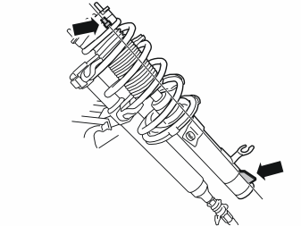
- Press the new spring together. Use hydraulic tool (P/N 9992911) together with claws (P/N 9992914).
Install:
- the spring
- the rubber bump stop together with the boot
- the spring seat
- the nut (M12). Use socket (P/N 999 5500) and a Torx socket as a counterhold. Tighten to 50 Nm (37 lbf. ft.).
Примечание: Ensure that the spring seat marking is opposite the spring strut guide when installing the spring.
- Reinstall the spring strut in the bodywork using new screws. Tighten to 30 Nm (22 lbf. ft.)
- Reinstall the stub axle on the spring strut
- Remove tool (P/N 9997088). See point 8
- Install a new screw in the stub axle. Tighten to 90 Nm (66 lbf. ft.)
- Remove the nut from the ball joint. Press down the control arm using tool (P/N 9997076). See step 4.
Reinstall:
- the drive shaft using a new screw. Tighten to 35 Nm (26 lbf. ft.) + angle tighten 90°
- the ball joint in the stub axle. Use tool (P/N 9997076)
- the new nuts for the ball joint. Tighten to 70 Nm (52 lbf. ft.)
- the brake calliper using two new screws. Tighten to 120 Nm (89 lbf. ft.)
- the anti-roll bar link
- the bracket for the ABS sensor
- the new nut (M10) for the anti-roll bar link. Tighten to 50 Nm (37 lbf. ft.)
- the brake hose in its bracket
- the front wheel. Tighten to 90 Nm (66 lbf. ft.)
- Repeat the above points on the other side.
Примечание: Wheel alignment must be carried out after finished work. Information about wheel alignment can be found in VIDA, group 6, path: Specifications ⇒ Mechanical specifications ⇒ General ⇒ General ⇒ Mechanical specifications.
Installing the rear lowering kit
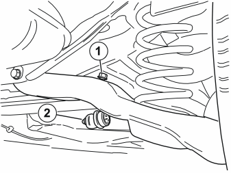
- Raise the car
- Remove the nut (1) from the ball joint for the anti-roll bar link on both the right and left-hand sides. Counterhold using a torx driver to prevent damage to the rubber boot
- Slacken off the nut (2) for the ball joint mount in the anti-roll bar on both the right and left-hand sides. Counterhold using a torx driver to prevent damage to the rubber boot
- Disconnect the link from the control arm. Twist the link downwards so that it is out of the way when the control arm is to be lowered.
Illustration A
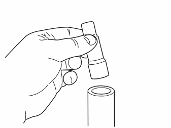
- Position sleeve (P/N 9995501) in the hole in the top of the garage lift, in order to secure it to the underside of the control arm.
Illustration B
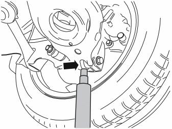
- Pump up the garage lift. Guide the top of the sleeve into the gap by the control arm bushing.
Illustration C
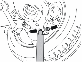
- Relieve the load on the screw joint. Remove the screw. Carefully lower the control arm until it is hanging freely
- Place the screw to one side. A new one is in the kit.
Внимание: Take care when working with tensioned springs. Follow the instructions carefully to avoid personal injury.
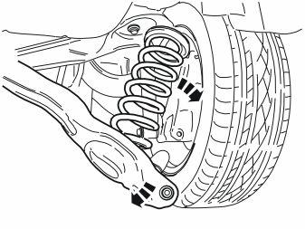
- Pull down the control arm. Then disconnect the old spring from the mountings in the bodywork / control arm. Remove the spring
- Remove the rubber liner from the old spring. The rubber liner will be used again
- Place the spring to one side. A new one is in the kit.
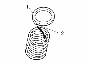
- Install the old rubber liner (1) on the new spring. Ensure that the end of the spring is correctly seated (2) in the rubber liner.
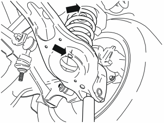
- Install the new spring in position
- Install the garage lift under the control arm again. Press the control arm carefully upwards. Check that the spring is correctly positioned in the seat in the control arm and in the bodywork
- Press the control arm to the correct position. Install a new screw from the kit.
Примечание: Do not tighten the screw securely yet. The car must be in the normal position when the screw is tightened.
- Repeat points 16-19 for the other spring.
- Reconnect the anti-roll bar links to the control arms
- Take new nuts from the kit (all the nuts removed will be replaced)
- Tighten the nuts in the anti-roll bar links to the control arms (1). Tighten to 50 Nm (37 lbf. ft.). Use a counterhold so that the rubber boots are not damaged
- Tighten the nuts in the anti-roll bar links to the anti-roll bar (2). Tighten to 70 Nm (52 lbf. ft.). Use a counterhold so that the rubber boots are not damaged
- Lower the car completely
- Tighten the new screws in the control arms. Tighten to 115 Nm (85 lbf. ft.).
Обсуждение и оценка
0Пока нет комментариев. Будьте первым.