Применимость
| Модель | Двигатель | Год |
|---|---|---|
| S60 (-09) | — | 2001–2009 |
Примечание: Cars without the accessories RTI, Sirius satellite radio or TV do not have the long Melbus cable, P/N 30664142, between the radio and the rear of the car. This is ordered separately.
If RTI is installed, then order Melbus cable P/N 8633596.
If Sirius satellite radio or TV is installed, then order Melbus cable P/N 8673298.
One some cars, the long Melbus cable may be pre-routed even though none of the aforementioned accessories is installed, sat. prep code 682. The cable end of this cable is then found near the rear fuse holder. To check whether the Melbus cable is installed, remove the left-hand folding side panel in the cargo compartment as described in step 30.
Примечание: - Model year -2004 = S60 CH - 424999
- Model year 2005- = S60 CH 425000-
Preparations, passenger compartment
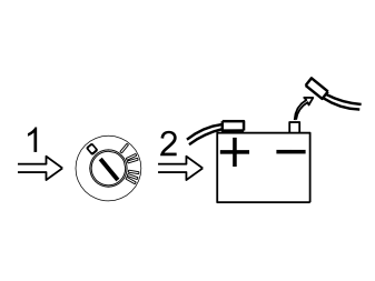
- Move the left front seat to its rearmost position
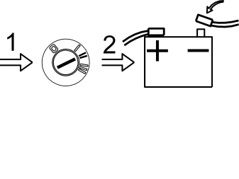
- Turn the ignition key to position 0.
- Disconnect the battery negative lead.
Примечание: Wait at least five minutes before disconnecting the connectors or removing other electrical equipment.
Steps 2 – 7 apply to cars up to and including model year –2004
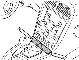
- Remove the panel in front of the gear selector lever. Pry off the panel using a plastic weatherstrip tool.
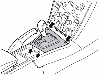
- Remove the panel around the gear selector. Press in the catches at the front edge and lift upwards. First lift at the front edge and then at the rear edge.
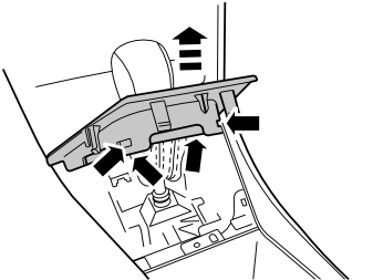
- Remove the panel around the gear selector. It is held in place with four catches.
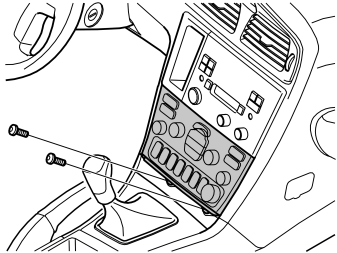
Only for cars without pre-routed Melbus cable
- Remove the two screws from the dashboard environment panel.
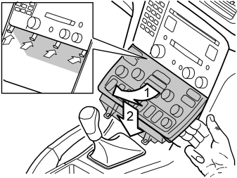
Only for cars without pre-routed Melbus cable
- Angle the dashboard environment panel outwards so that it is possible to insert a couple of fingers between the tunnel console and the reverse of the panel.
- Detach the dashboard environment panel by pulling it downwards while maintaining the same angle. Some force is required because the panel is tightly installed.
- Disconnect the connectors on the reverse of the dashboard environment panel. Place the dashboard environment panel to one side.
Примечание: If any of the outer hooks break off, these must be repaired. The method for this can be found in the Workshop Manual in the section about the dashboard.
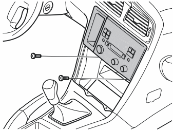
Only for cars without pre-routed Melbus cable
- Remove the screws from the radio bracket.
- Pull out the bracket with the radio. Pull the lower corner while pressing downwards.
- Detach the connectors from the radio and from the keypad to the telephone if fitted. Place the console with the radio to one side.
Steps 8–11 apply to cars from model year 2005–
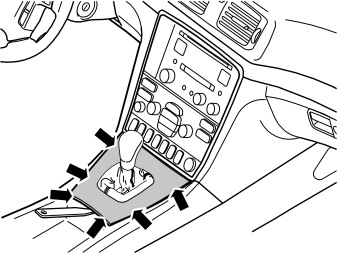
- Detach the rear edge of the gear selector lever cover together with the boot until the two clips release. Use a plastic weatherstrip tool. Remove the gear selector lever cover and the boot. Pull the panel up until the four clips at the sides release.
- Remove the panel around the gear selector. It is held in place with four catches.
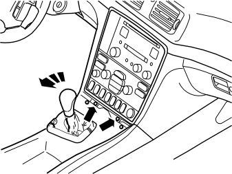
Only for cars without pre-routed Melbus cable
- Engage the handbrake and move the gear selector lever towards the rear.
- Remove the two screws holding the bracket with the radio and dashboard environment panel in the centre console.
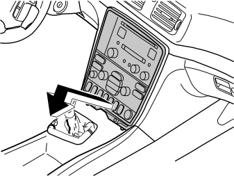
Only for cars without pre-routed Melbus cable
- Remove the bracket with dashboard environment panel and the radio from the centre console: Pull the lower edge out and downwards until it releases from the mounting at the upper edge. Then fold backwards.
Примечание: Do not damage the removed components or the surrounding panels.
- Disconnect the connectors from the radio and dashboard environment panel. Also disconnect the connector from the phone keypad if applicable. Place the unit to one side.
Applies to all models
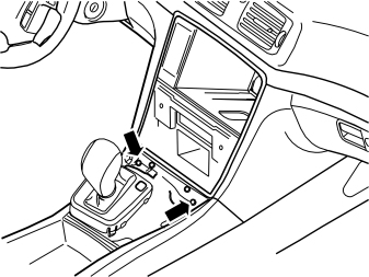
- Remove the two screws holding the front edge of the tunnel console in the centre console.
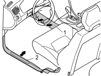
- Remove the side panel on both sides (1) of the tunnel console. First twist the clip at the rear edge of the panel a 1/4 turn. Pull the rear edge of the panel outwards and rearwards.
- Only for cars without pre-routed Melbus cable: Remove the sill trim panel (2).
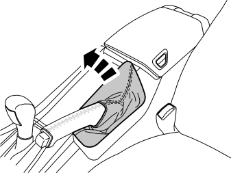
- Use a weatherstrip tool to carefully prise up the panel of the handbrake lever boot and remove it.
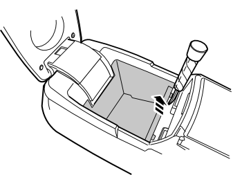
Applies to cars up to and including model year 2004
- Remove the bottom of the storage compartment by prying up the front edge and removing it.
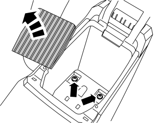
For cars from model year 2005-
- Remove the rubber mat at the bottom of the rear storage compartment and remove the two screws.
For cars with integrated telephone
- Remove the two rubber mats on each side of the privacy handset console.
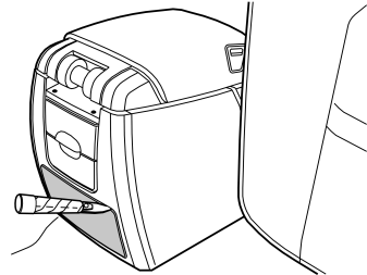
- Remove the panel in the rear edge of the tunnel console. Carefully pry off the panel using a plastic weatherstrip tool.
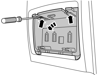
- Remove the holder in the panel (ashtray, if applicable) from the panel. First bend the catches on both sides at the upper edge downwards. Use a small screwdriver. Pull out the holder by the upper edge.
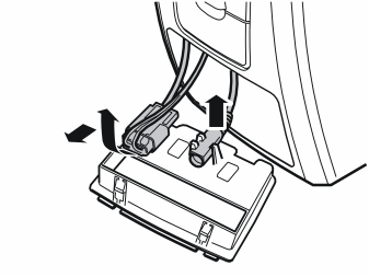
- Disconnect the connectors from the reverse of the holder (ashtray, if applicable). Place to one side.
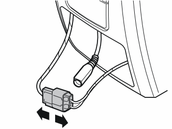
- Unplug the connector of the 12V socket.Unplug the connector of the integrated telephone (if installed).
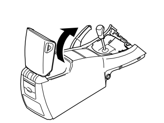
- Lift out the tunnel console. Be careful not to damage the trim on the handle of the handbrake lever.
Подсказка: Wrap the handle with tape for protection.
For cars from model year 2005- with integrated telephone
- Remove the handset with holder.
- Detach the cable with rubber grommet from the bottom of the storage compartment.
Preparations, tunnel console
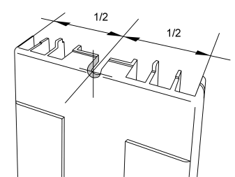
Applies to cars up to and including model year 2004
- File out a groove for the grommet of the iPod adapter cable using a round file.
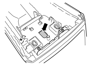
For cars from model year 2005-
- Cut along the existing marking in the bottom of the storage compartment for the cable from the iPod adapter. Even out the hole edges and remove any filings.
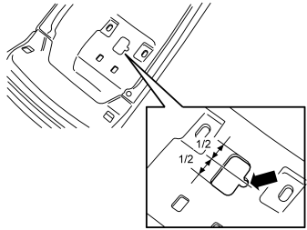
For cars from model year 2005- with integrated telephone
- File out a groove on the left side of the recess in the bottom of the storage compartment for the iPod adapter cable. File so that there is enough room for the cable to run freely when the rubber grommet is in place. Make sure that the cable does not chafe against the edges.
Preparations, passenger compartment, continued
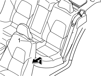
- Remove the rear seat cushion (1) by pulling it up at the front edge, pulling it forward and then lifting it away.
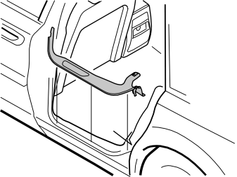
- Remove the sill trim panel at the left rear door.
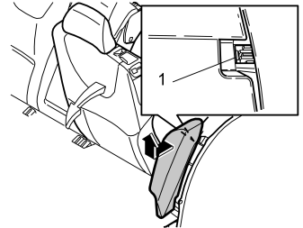
- Fold the left-hand rear seat backrest forward.
- Remove the left-hand side bolster. First press in the catch (1) at the top of the reverse of the side bolster, and pull it out slightly.
- Grasp the cushion using both hands. Twist anti-clockwise until the catches on the inside release.
- Remove the side bolster. First pull out the top of the side bolster. Then pull upwards.
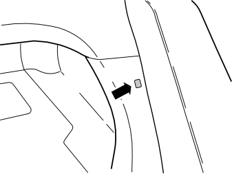
- Remove the clip at the side of the left-hand side bolster.
Cargo compartment, preparations
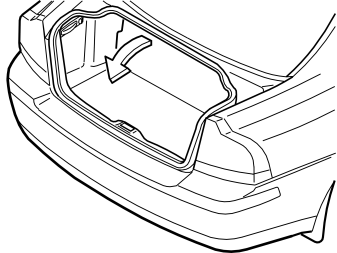
- Remove the cargo compartment carpet.
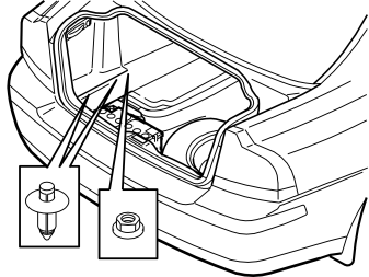
- Press in the centre of the clips on the lower edge of the folding side panel on the left-hand side until a click is heard.
- Remove the two clips.
- Remove the plastic nut at the front/lower edge of the side panel.
- Lower the panel and remove it.
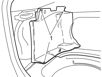
Remove:
- the clips (1) in the left-hand front side panel in the cargo compartment.
- the front side panel and place it to one side.
Installing the iPod adapter
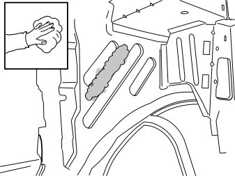
- Clean the marked surface of the plate over the left rear wheel housing using isopropanol, P/N 1161721-4, and wipe dry.
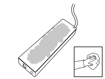
- Clean the marked surface on the iPod adapter using isopropanol, P/N 1161721-4, and wipe dry.
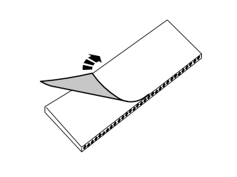
- Remove the protective backing tape from one of the velcro fastenings from the kit.
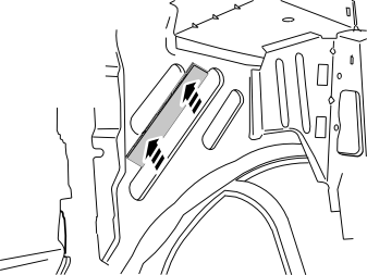
- Press the velcro fastening into place on the cleaned surface above the left wheel housing as illustrated.
- Remove the protective backing tape from the other velcro fastening from the kit.
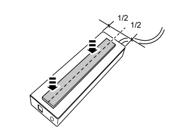
- Attach the Velcro fastener in the centre of the iPod adapter.
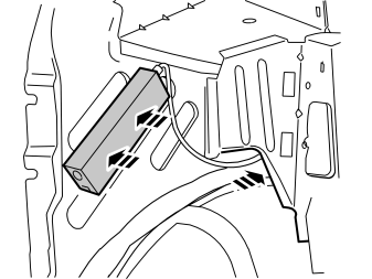
- Press the iPod adapter onto the velcro fastener in the body in the position illustrated.
- Insert the cable at the foam rubber insulation in the top edge of the wheel housing and route it to the front edge of the wheel housing. Route the cable inside of the lower part of the insulating panel and the rear part of the cable duct (Illustration B).
Примечание: Make sure that the adapter does not come into contact with the chassis ground.
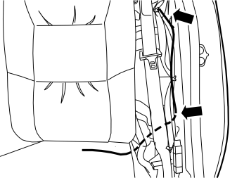
Cable routing
Applies to all models
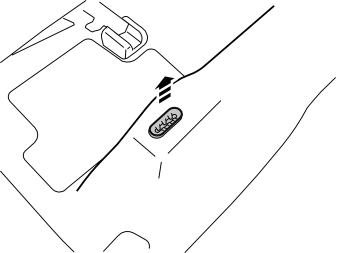
- Remove the holder on the left side of the rear seat.
Illustration A
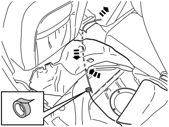
- Move aside the mat behind the left front seat.
- Insert a wire spiral under the mat between the front seats and up to the hatch below the seat cushion to the iPod adapter cable.
- Tape the routed cable to the wire spiral.
Illustration B
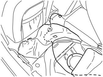
- Pull the cable up out of the mat between the front seats.
Примечание: Be sure not to damage the cable of the 12V socket located there or the mat.
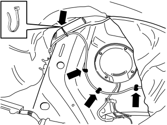
- Secure the cable with three pieces of butyl tape at the hatch under the seat cushion. Secure it at the cable duct using the tie strap from the kit.
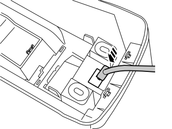
Applies to cars up to and including model year 2004
- Insert the iPod adapter cable in the bottom of the storage compartment and position the tunnel console. Make sure that the cable is positioned between the two spring nuts of the tunnel console's mounting.
- Adjust the length of the cable from the connector to the bottom of the storage compartment to 460 mm (18 1/8 "). Hide the excess cable length inside the mat.
- Fasten the tunnel console in using the existing screws.
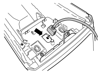
For cars from model year 2005- without integrated telephone
- Insert the iPod adapter cable in the bottom of the tunnel console's storage compartment.
- Reposition the tunnel console. Make sure that the cable is positioned between the two spring nuts of the tunnel console's mountings.
- Adjust the length of the cable from the connector to the bottom of the storage compartment to 460 mm (18 1/8 "). Hide the excess cable length inside the mat.
- Fasten the tunnel console in using the existing screws.
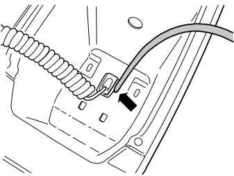
For cars from model year 2005- with integrated telephone
- Position the tunnel console with the rear high enough that the handset screw on the bottom can be tightened later.
- Insert the iPod adapter cable in the bottom of the storage compartment and position the cable in its recess.
- Insert the telephone handset cable through the handset holder and then into the hole in the bottom of the storage compartment. Press the rubber grommet into place.
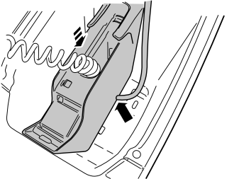
For cars from model year 2005- with integrated telephone
- Lower the handset into the storage compartment and put it in the correct position.
- Mark the left side of the handset where the iPod adapter cable shall go out.
- Remove the handset and fill a recess for the cable so that it runs freely. Make sure that the cable does not chafe against the edges.
- Adjust the length of the cable from the connector to the bottom of the storage compartment to 460 mm (18 1/8 "). Hide the excess cable length inside the mat.
- Reinstall the handset and tighten.
- If necessary, make a recess for the cable in the left rubber mat.
- Position the tunnel console and tighten the existing screws.
Applies to all models
- Remove the masking tape from the handbrake handle.
- Plug in the connectors of the 12V socket. If the car has an integrated telephone, plug in its connectors.
- Reinstall the connectors in the holder/ashtray.
- Reinstall the holder/ashtray and cover panel.
- Position the cable in the bottom of the storage compartment.
For cars from model year 2005-
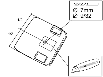
- Drill a Ø7 mm (9/32 ") hole in the rubber mat of the storage compartment in the position indicated for the iPod adapter cable.
- Cut the mat from the hole edge out to the edge using a carpet knife.
- Clean the hole so that the cable has room.
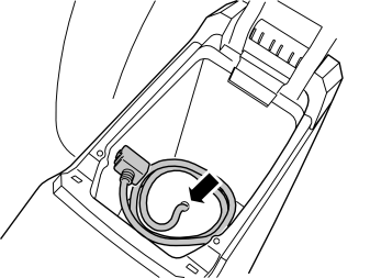
For cars from model year 2005-
- Reinstall the rubber mat/rubber mats (if the car has an integrated telephone) in the bottom of the storage compartment.
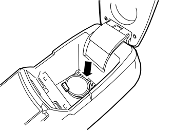
Applies to cars up to and including model year 2004
- Reposition the bottom of the storage compartment and press into place. Place the cable in its groove.
Only for cars without pre-routed Melbus cable
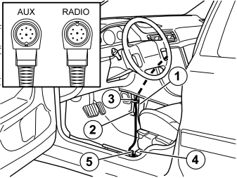
- Take the Melbus cablem P/N 30664142, lift up the floor mat and route it underneath, up between the front air duct (1) and the strut (2) for the centre console.
Примечание: Make sure that it is the connector with a guide pin which points upward (see illustration), which is routed to the radio socket.
- Route the cable through the compartment for the radio.
- Clamp the cable in the strut, using the clamp (3) from the kit.
- Route the cable on above and alongside the front air duct to the member (4) for the seat mounting.
- Clamp the cable at the existing cable harness (5).
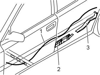
- Route the cable (1) under the carpet, along the left-hand side of the car to the rear door.
- Route the cable further above and along the front cable duct (2). Continue along the right-hand side of the rear cable duct (3).
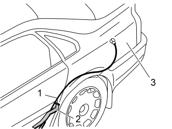
- Route the Melbus cable (1) on the right side of the cable duct (2), underneath the cables of such, and the up along the wheel housing following the same route as the iPod adapter cable and up to the adapter cable. Hide excess length of cable under the floor mat on the passenger side.
For cars with pre-routed Melbus cable
- Some cars are fitted with a long Melbus cable. Find the cable end, which is in the area (3) of the rear fuse holder.
- Pull back the cabe from the position at the fuse holder and up to the iPod adapter.
Routing of cable to power supply
For cars up to model year -2004 without RTI
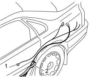
- Take the iPod adapter power supply cable, P/N 30660440, from the kit.
- Connect the ground cable to the front grounding point (1) in the rear seat and tighten to 10 Nm (7 lbf.ft.).
-
Route the power supply cable on the right side of the cable duct (2), underneath the cables of such. Then route up along the wheel housing following the same route as the iPod adapter cable and up to the adapter cable.Hide excess length of cable under the floor mat on the passenger side.
-
The cable end with the two loose red/white (R/W) wires is routed along existing cables to the rear fuse holder.Position the cable end with the blue connector at the iPod adapter. Make sure that the cable does not chafe against sharp edges.
- Clamp in the cable at the existing cable harnesses using three tie straps from the kit.
For cars from model year 2005- without RTI
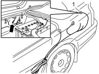
- Take the iPod adapter power supply cable, P/N 30660440, from the kit.
- Route the ground cable along existing cable harnesses towards the stern, along the cable harness there and up to the grounding point behind the battery.
- Connect the ground cable (1) to the existing grounding point and tighten to 10 Nm (7 lbf.ft.).
- Position the red/white (R/W) wires at the rear fuse holder.Position the cable end with the blue connector at the iPod adapter. Make sure that the cable does not chafe against sharp edges.
- Clamp in the cable at the existing cable harnesses using three tie straps from the kit.
For cars up to model year -2004 with RTI
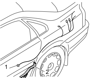
- Take the iPod adapter power supply cable, P/N 30660444, from the kit.
- Connect the ground cable to the front grounding point (1) in the rear seat and tighten to 10 Nm (7 lbf.ft.).
- Route the power supply cable on the right side of the cable duct (2), underneath the cables of such. Then route up along the wheel housing following the same route as the iPod adapter cable and up to the adapter cable. Hide excess length of cable under the floor mat on the passenger side.
- The cable end with the two loose red/white (R/W) wires and the two green connectors is routed along existing cables to the rear fuse holder.Position the cable end with the blue connector at the iPod adapter. Make sure that the cable does not chafe against sharp edges.
- Clamp in the cable at the existing cable harnesses using three tie straps from the kit.
For cars from model year 2005- with RTI
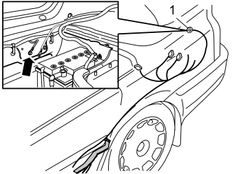
- Take the iPod adapter power supply cable, P/N 30660444, from the kit.
- Route the ground cable along existing cable harnesses towards the stern, along the cable harness there and up to the grounding point behind the battery.
- Connect the ground cable (1) to the existing grounding point behind the battery and tighten to 10 Nm (7 lbf.ft.).
- Position the red/white (R/W) wires and the green connectors at the rear fuse holder. Position the cable end with the blue connector at the iPod adapter. Make sure that the cable does not chafe against sharp edges.
- Clamp in the cable at the existing cable harnesses using three tie straps from the kit.
Applies to all models
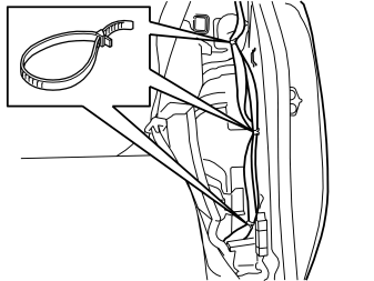
- Clamp all cables to each other along the wheel housing using tie straps from the kit.
Connection to the rear fuse holder, for cars without RTI
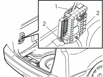
Applies to cars up to and including model year 2004
- Remove the fuse holder. Open the lock (1) on the top of the fuse holder. Fold the fuse box holder forward. Lift it out of the mountings (2).
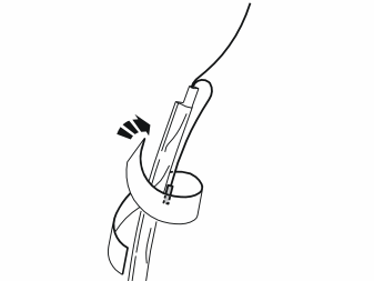
Applies to cars up to and including model year 2004
- Position the red/white (R/W) wire with the small cable terminal back along the cable. Insulate it and fasten it at the cable with foam tape from the kit (it must not come into contact with the chassis).
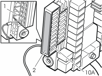
Applies to cars up to and including model year 2004
- Connect the routed red/white cable to the outer position (1) on the reverse side of fuse socket 10 on the fuse holder. Remove the decal (2). Carefully prize up the red secondary catch on the end face of the end closest to position 10 at the same time as the cable is pressed into place.
Подсказка: If there is a problem in routing the cable there then the fuses on the outer side must be removed so that the red secondary cable can be opened further.
- Reinstall the decal.
- Install a 10A fuse in fuse socket 10 on the fuse holder.
- Reinstall the fuse holder. Make sure that the cable does not chafe against sharp edges.
- Clamp in the cable at the existing cable harnesses using three tie straps from the kit.
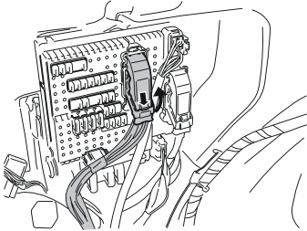
For cars from model year 2005-
- Press in the catch on the rear brown connector in the cargo compartment fuse holder. Turn up the lock arm as far as possible and pull out the connector.
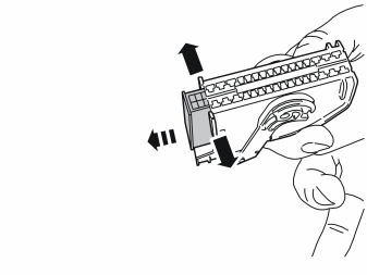
For cars from model year 2005-
- Carefully prise apart the sides of the connector holder in the ends so that the connector can pass by the retaining hooks.
- Pull out the connector.
For cars from model year 2005-
- Position the red/white (R/W) wire with the large cable terminal back along the cable. Insulate it and fasten it at the cable with foam tape from the kit (it must not come into contact with the chassis).
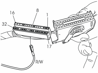
For cars from model year 2005-
- Connect the red/white (R/W) cable with the small cable terminal to position 8 in the connector.
- Reposition the connetor in the holder and reinstall the entire unit in the fuse holder. Make sure that the cable does not chafe against sharp edges.
- Clamp in the cable at the existing cable harnesses using three tie straps from the kit.
Connection to the iPod adapter
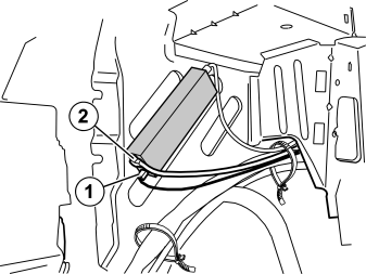
For cars without RTI, Sirius satellite radio or TV
- Plug in the blue connector (1) for the iPod adapter's power supply.
- Connect the routed Melbus cable (2) to the iPod adapter.
- Clamp in all cables at existing cable harnesses using tie straps from the kit. Use the hole in the plastic edge at the rear edge of the wheel housing to fasten the tie straps. Make sure that the cables do not chafe against sharp edges.
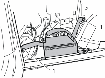
Applies to cars with RTI (road traffic information)
- Remove the two screws (1) in the DVD drive bracket and remove the bracket with DVD drive.
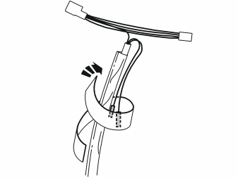
Applies to cars with RTI (road traffic information)
- Position the two red/white (R/W) wires back along the cable. Insulate and fasten them at the cable using foam tape from the kit. They must not come into contact with the chassis. The two green connectors should be loose.
Applies to cars with RTI (road traffic information)
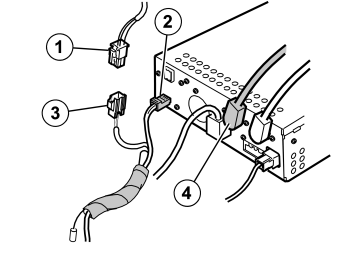
Connection to the DVD unit
- Unplug the DVD power supply connector (1).
- Plug in the connector of the iPod adapter power supply into the DVD unit (2).
- Plug in the connector unplugged from the DVD unit into the other connector of the iPod adapter (3).
- Connect the Melbus cable (4), P/N 8633596, to the DVD unit.
- Reposition the bracket with DVD drive and fasten it with the three screws.
- Clamp in the cable at existing cable harnesses using tie straps from the kit. Make sure that the cable does not chafe against sharp edges.
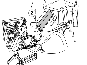
Applies to cars with RTI (road traffic information)
- Plug in the blue connector (1) for the iPod adapter's power supply.
- Connect the Melbus cable (2), P/N 8633596, from the DVD unit.
- Clamp all cable harnesses and excess Melbus cable together with existing cable harnesses using tie straps from the kit. Use the hole in the edge of the plate at the rear edge of the wheel housing to secure the tie strap. Make sure that the cables do not chafe against sharp edges.
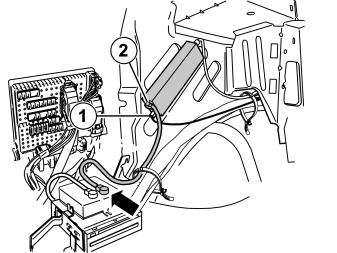
For cars with Sirius satellite radio or TV
- Plug in the blue connector (1) for the iPod adapter's power supply.
- Connect the Melbus cable (2) P/N 8673298 between the iPod adapter and the Sirius/TV unit.
- Clamp all cable harnesses together with existing cable harnesses using tie straps from the kit. Use the hole in the edge of the plate at the rear edge of the wheel housing to secure the tie strap. Make sure that the cables do not chafe against sharp edges.
Applies to all models
- Reinstall the side panel and folding panel in the cargo compartment.
- Reposition the insulating and floor mats.
- Reinstall the sill panels.
- Reinstall the seat cushion.
- Reinstall the side bolster.
- Restore the backrest to its original position.
- Reinstall the side panels of the tunnel console.
- Connect the Melbus cable and other disconnected cables of the radio/dashboard environment panel and reinstall the units.
- Reinstall the panel/panels at the gear selector lever.
- Turn the ignition key to position II.
- Connect the negative battery lead.
- Reinstall the cargo compartment carpet.
Functionality check
- Connect an iPod unit with stored music.
- Check that the adapter controls the iPod unit: "Volvo for life" and "OK to disconnect" appear on the iPod unit display. The scroll wheel and menu buttons of the iPod adapter are locked.
- Select "CD changer" using the SOURCE button on the radio.
- Check that the iPod unit plays. If it does not have any defined playlists, only CD 10 (playlist 10) will be played.
Обсуждение и оценка
0Пока нет комментариев. Будьте первым.