Применимость
| Модель | Двигатель | Год |
|---|---|---|
| XC90 | — | 2003, 2004 |
Примечание: This accessory is connected to the electrical system of the car. It requires software unique to the car.
Preparations
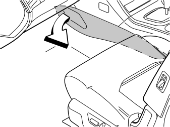
- Remove the left and right-hand side panels from the centre console. Pull the panels free at the front edge and continue backwards until all the clips have released.
Applies to cars with power front seats
- Position the right-hand front seat so that:
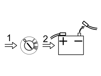
- Turn the ignition key to position 0
- Disconnect the battery negative lead.
Примечание: Wait at least five minutes before disconnecting the connectors or removing other electrical equipment.
Illustration A
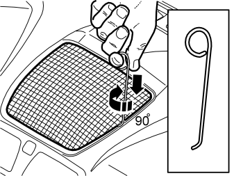
- Take a length of 1.5 mm (1/16”) diameter welding rod. Bend one end to 90°, L=5 mm (13/64”)
- Bend the other end to form a handle
- Insert the first bent end into the joint between the loudspeaker grille and the dashboard as illustrated, until it engages
- Twist the welding rod 90° so that the bent section engages with the underneath of the loudspeaker grille. It may be necessary to move the welding rod along the joint so that it can be twisted around.
Illustration B
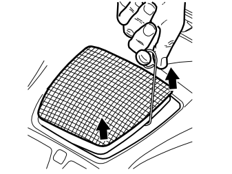
- Pull up until the loudspeaker grille detaches. The grille is well secured using four clips.
Примечание: Do not damage the dashboard.
- Place the loudspeaker grille to one side.
Removing the loudspeaker grille:
Illustration A applies to cars without a centrally-mounted loudspeaker
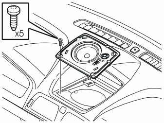
- Remove the bracket for the loudspeaker grille. Remove the five screws and pulling the bracket up out of the dashboard.
Illustration B applies to cars with a centrally-mounted loudspeaker
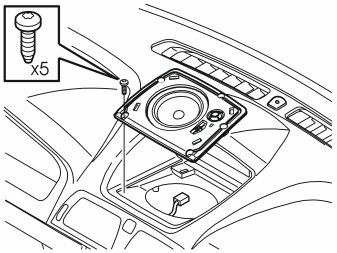
- Remove the five screws from the loudspeaker. Pull the loudspeaker slightly out of the dashboard. Disconnect the connector.
Illustration C applies to cars with RTI (road traffic information)
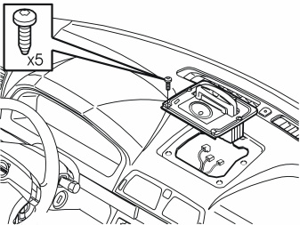
- Remove the five screws in the display for RTI (road traffic information). Pull up the display slightly from the dashboard. Disconnect the connectors
- Disconnect the loudspeaker for the centrally-mounted if installed.
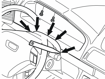
- Lower the steering wheel to the lowest position. Pull the steering wheel to the rearmost position
- Remove the two screws at the top edge of the combined instrument panel surround
- Carefully pry off the rubber seal from the upper steering column cover. Use a weatherstrip tool. It is secured with five clips
- Remove the surround by carefully pulling it backwards, first at the lower edge and then at the top edge until all the clips have released.
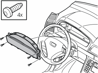
- Remove the four screws for the combined instrument panel
- Pull out the combined instrument panel. Disconnect the connector on the reverse of the combined instrument panel.
Applies to cars with automatic gearboxes
- Turn the ignition key to position II.
Applies to all models
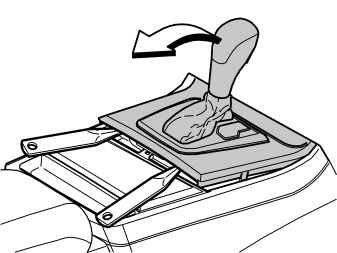
- Move the gear selector lever to its rearmost position
- Carefully pry off the gear selector lever panel at the rear edge using a weatherstrip tool. Pull the panel backwards to access the screws for the dashboard environment panel.
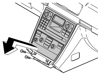
- Remove the two screws holding the bracket for the dashboard environment panel and the control module
- Pull out the bracket at the lower edge. Pull downwards from the top edge of the centre console
- Disconnect the connectors from the dashboard environment panel and control module
- Disconnect the connectors for the CD-player and/or Mini disc player if applicable.
Preparations, carphone holder
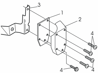
- Take the carphone holder bracket, the reinforcement plate, the cover and screws from the kit
- Install the reinforcement plate (1) and the cover (2) in the bracket (3) using the screws (4).
Illustration A
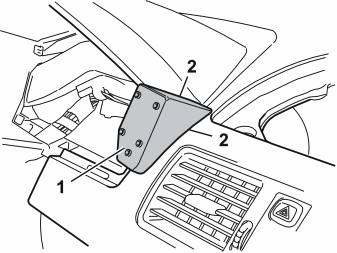
- Position the entire unit (1) in the dashboard to mark out the holes for the bracket. Adjust to achieve the optimum position. Do not press the unit hard against the dashboard. However, ensure that there are no gaps at the sides between the panel and the dashboard (2).
Illustration B
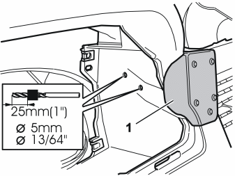
- Hold the unit in place and mark out the holes through the bracket
- Drill out the two holes using a 5 mm (13/64”) diameter drill bit. Use a 25 mm (1”) drill stop
- Remove any swarf
- Remove the cover and the reinforcement plate from the bracket.
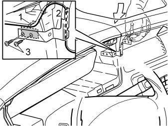
- Take the reinforcement plate (1) and the two screws from the kit
- Position the carphone holder wiring, which is routed on the reverse of the bracket, as illustrated
- Insert the reinforcement plate through the hole for the centre loudspeaker
- Install the bracket (2). Use the two screws (3). Tighten the bracket to the dashboard.
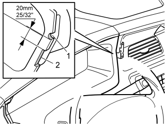
- Press the surround for the combined instrument panel into place
- Mark out the surround, as illustrated, where the cut-outs will be made for the wiring and the bracket for the handset holder
- Remove the surround. File out the groove (1) for the wiring for the handset. File the hole so that it is large enough for any excess wiring to be routed through the hole and hidden on the inside of the dashboard
- File out a groove (2) for the bracket for the handset holder
- Smooth off the edges of the groove.
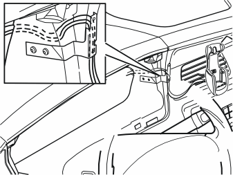
- Route the wiring for the carphone holder from the hole for combined instrument panel. Position the wiring at the left air duct in the centre console. Do not route more wiring than is required to secure the carphone holder.
Installing the microphone
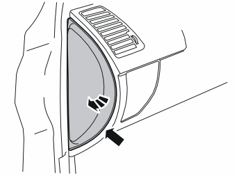
- Pry off the rear edge of the panel on the left-hand end of the dashboard. Twist out the panel. Remove the panel.
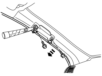
- Pry up the covers on the grab handle at the arrows. Remove the screws underneath
- Pull off the rubber strip from the door opening.
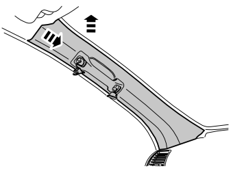
- Pull off the top edge of the A-post panel. Pull the panel straight up to remove it.
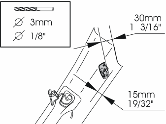
- Take the mounting plate from the kit. Position the mounting plate on the top end of the A-post panel. See the illustration. If the microphone is already installed in the mounting plate, remove it. It is secured by two hooks on the long sides
- Mark out and drill the holes for the mounting plate. Use a 3 mm (1/8”) diameter drill bit
- Remove any swarf.
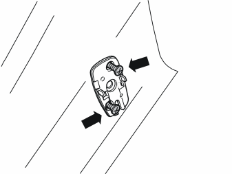
- Install the mounting plate on the A-post panel using two screws from the kit.
Осторожно: The inflatable curtain (IC) is located inside the A-post panel. It is important to file off the screws securing the mounting plate if necessary, so that they just fit through the panel.
- Check how much of the screws protrudes on the reverse. Unscrew the screws. File off the screws to the correct length
- Reinstall the screws.
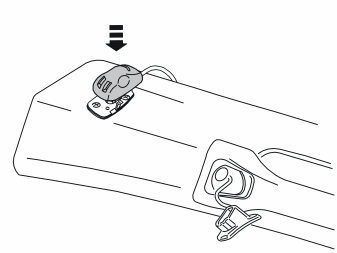
- Press the microphone from the kit into place on the mounting plate.
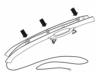
- Route the microphone cable on the inside of the A-post panel. Secure the cable using pieces of butyl tape.
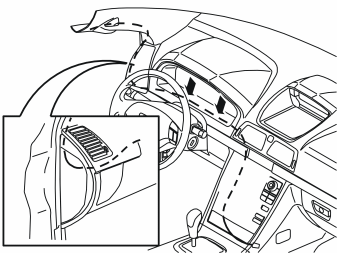
- Press the A-post panel into place. Install the screws. Tighten to 10 Nm (7 lbf. ft.)
- Press the covers into place over the screws
- Route the microphone cable in through the left-hand end of the dashboard, into the space for the combined instrument panel and into the centre console
- Secure the cable where it runs under the combined instrument panel using pieces of butyl tape
- Connect the combined instrument panel. Reinstall the combined instrument panel
- Reinstall the surround for the combined instrument panel. Tighten
- Reinstall the left-hand end panel on the dashboard.
Installing the carphone holder
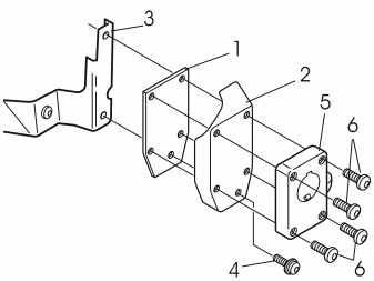
- Install the reinforcement plate (1) and the cover (2) in the bracket (3). Use the screw (4) from the kit. Do not tighten fully yet
- Remove the mounting plate (5) for the carphone holder from the carphone holder. Tighten the mounting plate using the screws (6) from the kit
- Tighten the screw (4)
- Install the carphone holder on the mounting plate
- Route unnecessary excess wiring into the hole for the combined instrument panel.
- Route the cable for the carphone holder to the centre console and out to the right-hand side of the centre console
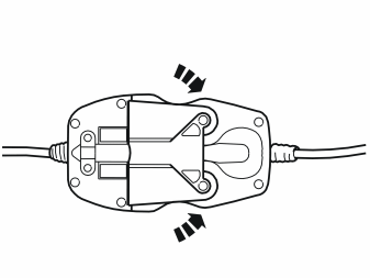
- Connect the cable for the carphone holder to the cable for the hands free box.
Примечание: Ensure that the connector is correctly aligned. The two mounting lugs on the reverse must be in their grooves.
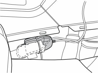
- Clamp the connector on the right-hand side of the centre console, where there is no risk of it being damaged.
Connection to the amplifier
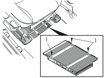
- Slacken off the 3 screws (1) for the amplifier under the right-hand front seat.
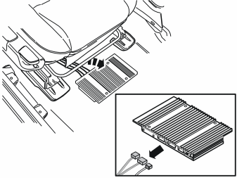
- Lift out the amplifier. Use a weatherstrip tool to lift it up from its sunken position
- Disconnect the connectors in the amplifier
- Take the wiring from the kit.
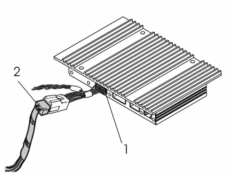
- Connect one of the green connectors (1) on the hands free cable to the amplifier and the other to the green connector that was connected to the amplifier (2)
- Reach under the floor carpet and push the insulation material to one side
- Take the end of the hands free cable with grey connectors in the other hand. Insert the connectors under the floor carpet through the hole where the amplifier was positioned
- Lift up the floor carpet and make room for your hands to meet under it
- Take the cable and carefully route it into the centre console.
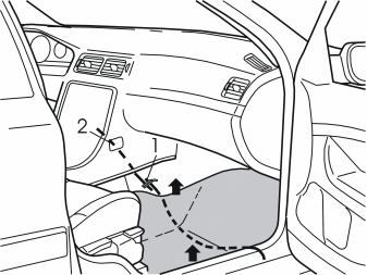
- Pull up the left and right-hand sides of the carpet a little
- Insert a wire (1) under the carpet at the front edge of the air ducts on the right-hand side of the centre console, and route it out at the right-hand door sill
- Take the single cable going to the Accessory Electronic Module (AEM). Tape the cable to the wire
- Route the cable forward from the carpet at the right-hand door sill.
Installing the hands free box
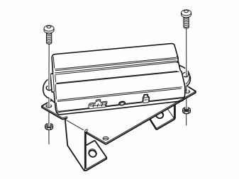
- Take two screws and nuts from the kit. Tighten the hands free box to the bracket.
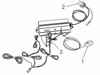
- Connect the wiring for the hands free box as illustrated
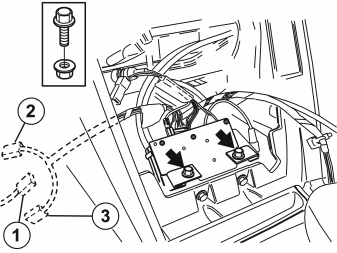
- Turn down the bracket and the hands free box
- Install the hands free box in the hole for the dashboard environment panel
- Take two screws and nuts from the kit. Install the bracket with the hands free box on the existing bracket at the lower edge of the centre console.
Примечание: Ensure that the none of the wiring is trapped.
- Locate the grey (GR) pre-routed connector (1) for power supply. This comes from the heavy duty cable harness, either under the dashboard on the right-hand side of the steering wheel, immediately above the accelerator pedal (AP), or if the car has a Mini disc player and/or CD-player, the connector may be on the junction cable for these components.
Cars which do not have a pre-routed connector in the cut-out for the radio
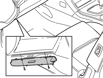
- Remove the soundproofing panel on the left-hand side. First remove the two screws, then pry off the soundproofing panel at the top edge (see illustration B).
Applies to all models
- Take the cable harness with the two grey (GR) connectors which was previously connected to the hands free box. Route it out through the left-hand side of the centre console to the existing connector
- Connect the pre-routed connector to the corresponding connector (2) on the routed cable harness
- Secure the excess connector (3)
- Clamp the cable harness so that it is not in contact with any sharp edges and is not at risk of any other damage.
Cable routing to the accessory electronic module (AEM)
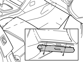
- Detach the soundproofing panel on the right-hand side of the centre console. First remove the two screws. Then pry off the panel at the top edge.
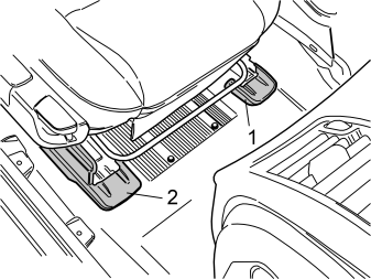
Points 35-36 refer to the right-hand front seat
- Remove the cover (1) on the left-hand front mounting by prying it off at the front edge
- Pry off the front edge of the right-hand panel (2). Remove the panel.
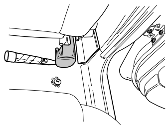
- Remove the panel on the right-hand rear mounting. Pry it up slightly at the rear edge and then pull it back / upwards.
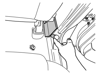
- Remove the panel over the joint between the door sills on the right-hand side. Carefully pry off the panel at the lower edge using a weatherstrip tool.
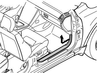
- Remove the sill trim panel for the right-hand front door. Pull off the front edge of the sill trim panel so that the clip releases. Continue backwards until the remaining clips have released
- Unhook the sill trim panel from the B-post panel.
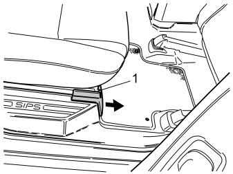
Points 39-40 refer to the right-hand seat in the second row
- Remove the panel in the right-hand front seat mounting. Push up the catch (1) on the top. Pull the panel forward.
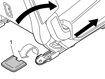
- Fold the backrest forward and slide the front seat forward as far as possible. (On cars with two rows of seats, the second row is fixed.)
- Remove the cover (1) for the right rear seat mounting by prying it off at the rear edge.
Illustration A
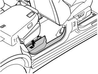
- Remove the sill trim panel for the right-hand rear door. Pull off the rear edge so that the clips releases. Continue forwards until the remaining clips have released.
Applies to cars with two rows of seats
- On cars with two rows of seats the seat cannot be slid forwards. To remove the sill trim panel; Start by folding the backrest forward when pulling the rear edge of sill trim panel loose. Then re-position the backrest to raise the seat cushion and provide more room for removing the sill trim panel. It is securely positioned. Do not damage the panel and surrounding components during removal.
Illustration B
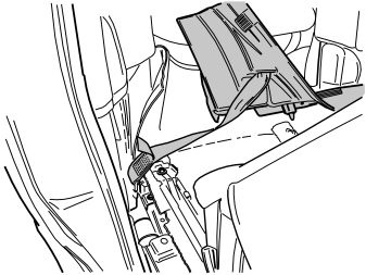
- Unhook the sill trim panel from the B-post panel. Position the panel in the second/third row of seats.
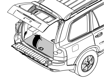
Applies to cars with three rows of seats and integrated carrier bag holder on the underside of the centre floor hatch
- Fold the rear centre floor hatch up
- Detach the two straps from the panel below. Lift up the rear edge of the panel. Fold the floor hatch back towards the panel and lift out the floor hatch and the panel.
Applies to cars with three rows of seats without an integrated carrier bag holder
- Lift up the centre rear floor hatch at the rear edge and lift it out.
Applies to cars with two rows of seats
- Remove the two centre floor hatches. First lift them up slightly and then pull them loose from the mountings at the front edge
- If the rear centre floor hatch has a carrier bag holder on the lower side, the floor hatch is secured by a strap on each of the shorter sides of the storage box. Undo these straps
- Remove the two storage boxes below.
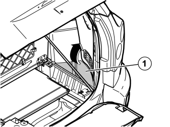
- Remove the right-hand side floor hatch (1).
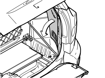
- Remove the folding side panel from the right-hand side in the cargo compartment.
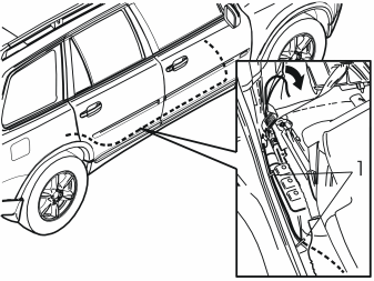
- Insert the cable harness between the carpet and the door sill towards the floor as far as it will go. Route it along the right-hand side of the car up to the rear edge of the door opening for the right-hand rear door
- Pull the cable harness up to the right-hand front seat mounting on the right-hand seat in the second row of seats
- Pull away the carpet from the front edge of the right-hand side panel in the cargo compartment
- Route the cable harness along the right-hand side of the right-hand seat in the second row of seats towards the front edge of the rear wheel arch. Route it onwards on the left-hand side of the lower mounting for the seat belt, between the support bracket for the right-hand seat and wheel arch, and out at the left-hand side of the wheel arch
- Clamp the cable harness in the hole in the front member for the seat mounting and in the rear hole in the horizontal plate at the right-hand side of the seat. Use the tie straps (1) (from the kit).
Applies to cars with three rows of seatsIllustration A
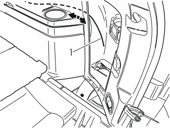
- Insert a wire (1) at the rear edge of the right-hand side panel and along the inside of the panel, above the mountings for the load securing eyelets. Route the wire to the front edge of the side panel.
Illustration B
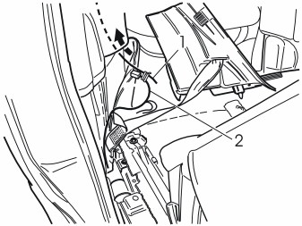
- Tape the cable harness (2) to the wire and pull it out of the rear edge of the side panel.
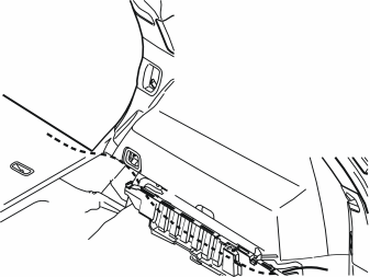
Applies to cars with two rows of seats
- Route the cable on the left-hand side of the seat belt mounting at the front edge of the wheel arch, inside the carpet at the front edge of the side panel, between the side panel and the rear of the cargo floor support, to the accessory electronic module (AEM).
Connecting to the accessory electronic module (AEM)
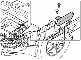
- Remove the two screws from the bracket for the accessory electronic module (AEM) and lift up the entire unit. Cut off the tie straps if necessary.
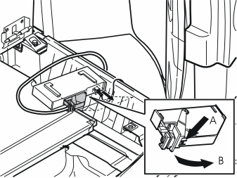
- Disconnect the large connector from the accessory electronic module (AEM). First press in the catch (A). Pull the black locking handle (B) in the direction of the arrow until a click is heard. Disconnect the connector
- Disconnect the connector from the accessory electronic module.
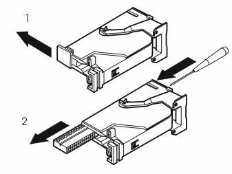
- Remove the black catch holding the black switch in place in the connector by pulling in the direction of the arrow
- Remove the black switch. Insert a pointed object in the hole on the other end of the connector. Press the switch out.
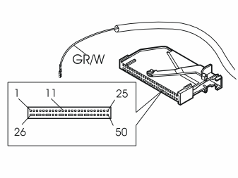
- Connect the Grey/White (GR/W) cable from the routed cable harness to terminal 11 (tele-mute) in the black connector for the accessory electronic module (AEM).
Примечание: The numerical markings are on the top and bottom of the black switch. However, the markings are extremely small so be careful when installing the two cables.
- Reinstall the black switch in the connector. Lock into place using the catch
- Press the connector into the accessory electronic module (AEM). Secure using the black locking handle
- Reinstall the accessory electronic module (AEM) with the bracket and clamp the wiring using the tie strap from the kit.
Примечание: If the car is to be equipped with the accessory windscreen aerial, it should be installed at this stage before the components on the right-hand side of the car are reinstalled.
- Reinstall the folding panel on the right-hand side in the cargo compartment
- Reinstall the right-hand side floor hatch
- Reinstall the carpet at the front edge of the right-hand side panel
- Reinstall the sill trim panel in the right-hand rear door
- Reinstall the cover(s) over the seat mountings on the second row of seats.
Installing the integral antenna
Подсказка: The Volvo windscreen antenna can also be used.
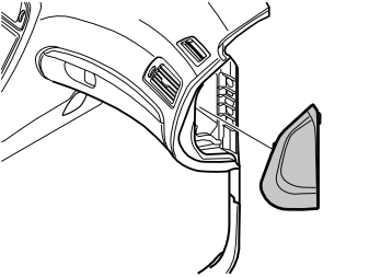
- Remove the panel on the right-hand end of the dashboard.
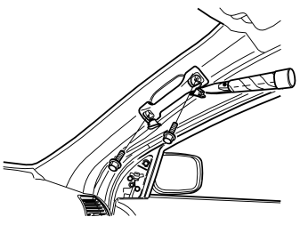
- Pry off the cover on the grab handle in the right-hand front door. Remove the screws below.
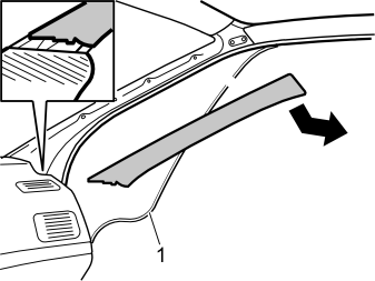
- Remove the rubber strip (1) at the front edge of the right-hand front door
- Remove the right-hand A-post panel by carefully pulling the top edge of the panel outwards until the clip on the inside releases. Pull it up out of the mounting in the dashboard.
Примечание: Do not damage the headlining.
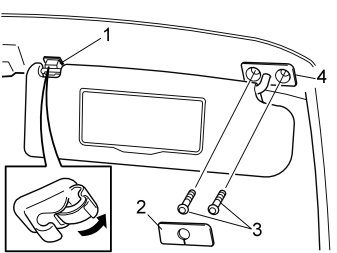
- Remove the sun visor from the inner mounting (1) on the right-hand side
- Carefully pry the cover (2) off. Remove the two screws (3) for the sun visor mounting
- Remove the inner mounting (1) by first prying up the catch as illustrated. Then insert a small screwdriver in the rear edge of the exposed hole and press the sprung catch forward to release it from the hole in the roof. A the same time pull the rear edge of the mounting downward/backwards so that the catch at the front edge and both catches at the sides release.
Примечание: Do not damage the headlining.
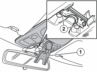
- Fold down the cover (1) by carefully pulling down the front edge of the cover
- Squeeze the catches (2). Pull the front edge of the panel downwards. Then pull the rear edge off.
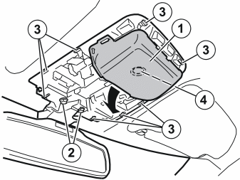
- Remove the rear view mirror and the front interior lighting (1). First remove the two screws (2) and then press in the eight catches (3) around the interior lighting
- Carefully pull the components downwards and allow them to hang by their wiring. (The interior lighting is secured to the roof using the clip (4).).
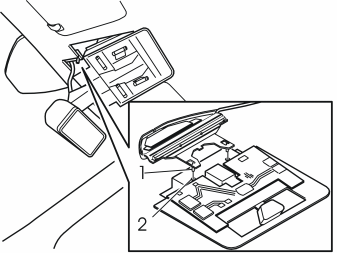
- Install the new antenna. Carefully bend the headlining downward and slide the antenna backward and inwards. Align the antenna lugs (1) with the grooves in the bracket (2)
- Insert the cable at the inside of the front edge of the headlining. Route the cable out towards the right-hand A-post
- Secure the cable using butyl tape
- Reinstall the bracket and rear view mirror. Tighten the screws. Tighten to 10 Nm (7.5 lbf. ft.)
- Reinstall the panel. Securely lock the panel using the cover.
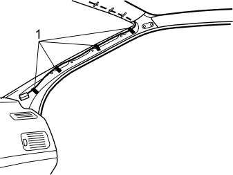
- Route the cable down from the headlining along the right-hand A-post
- Tape the cable onto the existing cable harness as illustrated (1).
Внимание: Ensure that the cable is not routed over the inflatable curtain. This could compromise the function of the inflatable curtain in the event of an accident.
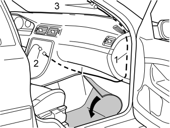
- Push the carpet to one side by the right-hand front seat
- Take the extension cable (1) from the kit. Route the cable between the A-post and the right-hand side of the dashboard, continue along the right-hand end to the front edge of the floor
- Route the cable to the left along the front edge of the floor and up to the inside of the centre console
- Connect the cable (1) to the corresponding cable (2) from the hands free box
- Connect both connectors (3) at the right A-post to each other
- Wrap foam tape around the connectors to prevent rattling.
- Reinstall the A-post panel. Tighten the grab handle. Tighten to 10 Nm (7.5 lbf. ft.). Reinstall the cover
- Reinstall the rubber strip in the right-hand front door
- Reinstall the panel on the end of the dashboard
- Reinstall the sun visor. Tighten the screws. Tighten to 10 Nm (7.5 lbf. ft.). Also reinstall the cover and the inner mounting
- Fold the carpet on the right-hand side back into place
- Reinstall the panel on the door trim for the right-hand front door. Press the lower panel into place on the B-post
- Reinstall the soundproofing panel on the right and left-hand sides
- Reinstall the cover and panel on the right-hand front seat
- Connect the connectors to the dashboard environment panel and control module. Also connect the connectors for the CD-player and/or Mini disc player if applicable
- Position the bracket. Tighten the bracket using the two screws. Reinstall the gear selector lever panel
- Reinstall (depending on the equipment in the car):
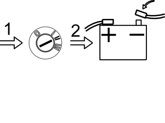
- Connect the connectors to the amplifier
- Reinstall the amplifier in its folded down position. Tighten the screws
- Turn the ignition key to position II
- Reconnect the battery negative lead
- Reinstall the storage boxes and floor hatch(es)
- Reinstall both the side panels on the centre console
- Program the software using VCT2000 according to the service information in VIDA.
Обсуждение и оценка
0Пока нет комментариев. Будьте первым.