Примечание: This accessory is connected to the electrical system of the car. It requires software unique to the car.
Подсказка: Points 38-67 apply to cars with an accessory electronic module (AEM).
Preparations
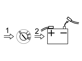
- Slide back the front seats to the rearmost and uppermost positions
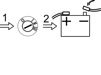
- Turn the ignition key to position 0
- Remove the key from the ignition switch (does not apply to cars with automatic gearboxes)
- Disconnect the battery negative lead.
Примечание: Wait at least five minutes before disconnecting the connectors or removing other electrical equipment.
Dashboard preparations
Illustration A applies to cars equipped with a centre storage locker
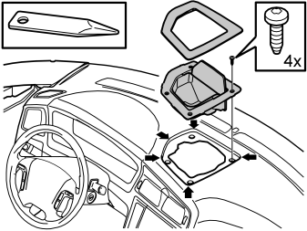
- Carefully remove the storage locker surround. First pry up the surround using a weatherstrip tool
- Remove the four screws around the storage locker. Place the locker to one side.
Illustration B applies to cars equipped with a centrally-mounted loudspeaker
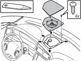
- Carefully pry the loudspeaker grille up using a weatherstrip tool. Remove the loudspeaker grille
- Remove the screws in the loudspeaker
- Lift up the loudspeaker. Disconnect the connector
- Place the loudspeaker to one side.
Illustration C applies to cars equipped with RTI
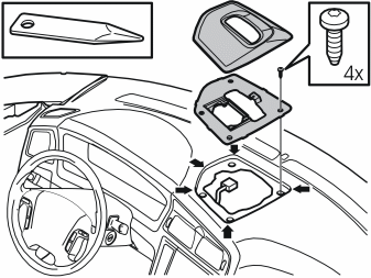
- Carefully remove the panel around the RTI display. Carefully prise around the panel using a weatherstrip tool
- Remove the four screws in the holder for the display
- Lift the entire RTI unit. Disconnect the connector for the display. Where applicable, also disconnect the connector for the centrally mounted loudspeaker
- Place the complete unit to one side.
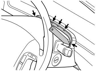
- Lock the steering wheel in the lowest, rearmost position
- Remove the rubber seal from the upper steering column cover by carefully prying the 5 catches loose using a weatherstrip tool.
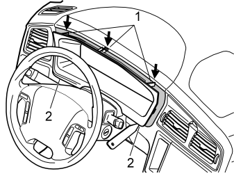
- Pry out the two clips (2) in the bottom edge of the combined instrument panel. Carefully remove the combined instrument panel surround
- Pull the surround back until the three clips (1) at the top edge release.
Примечание: Do not damage the dashboard.
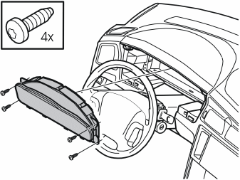
- Remove the four screws for the combined instrument panel
- Pull out the combined instrument panel. Disconnect the connector on the reverse of the combined instrument panel
- Place the combined instrument panel to one side.
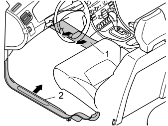
- Remove the side panel (1) on the centre console. First twist the clip at the rear edge of the panel a 1/4 turn. Pull the rear edge of the panel outwards and backwards
- Remove the sill trim panel (2).
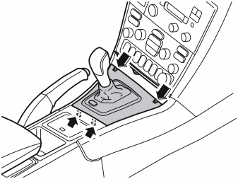
- Remove the panel around the gear selector. Press in the catches at the front edge and lift upwards. First lift at the front edge and then at the rear edge.
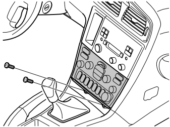
- Remove the two screws from the dashboard environment panel.
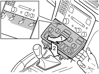
- Angle the dashboard environment panel outwards so that it is possible to insert a couple of fingers between the centre console and the reverse of the panel
- Detach the dashboard environment panel by pulling it downwards while maintaining the same angle. Some force is required because the panel is tightly installed
- Disconnect the connectors on the reverse of the dashboard environment panel. Place the dashboard environment panel to one side.
Примечание: If any of the outer hooks break off, these must be repaired. The method for this can be found in the Workshop Manual in the section about the dashboard.
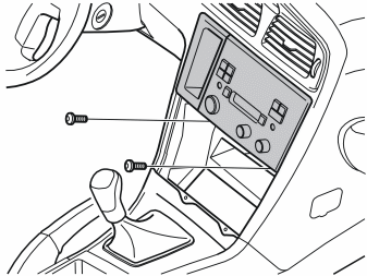
- Remove the screws from the radio bracket
- Pull out the bracket with the radio. Pull the lower corner while pressing downwards
- Disconnect the connectors for the radio. Place the bracket with the radio to one side.
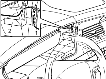
- Remove the screw (1) securing the semi circular section of the dashboard above the combined instrument panel
- Take the handset holder and bracket (2) from the kit
- Position the bracket with the cable routed on the reverse of the bracket as illustrated
- Tighten the bracket using the screw (1) for the semi circular section
- Route the cable down into the hole behind the dashboard.
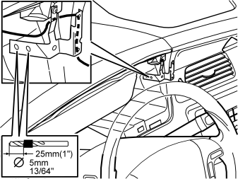
- Press the bracket against the mating surfaces where the three holes are to be drilled
- Hold the bracket firmly in place. First drill the two marked holes through the bracket and the dashboard. Use a 5 mm (13/64") diameter drill bit. Use a 25 mm (1") diameter drill stop.
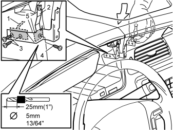
- Insert the bracing plate (1) through the hole in the dashboard
- Secure the bracket (2) using two screws (3) from the kit while pressing the bracket against the mating surfaces
- Tighten the screws so that the bracket is pressed into and is at the same level as the dashboard face
- Drill out the last hole. Use a 5 mm (13/64") diameter drill bit
- Insert the bracing plate (5) through the hole in the dashboard
- Secure the bracket using a screw (4) from the kit.
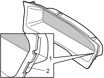
- Mark out the hole for the cable for the handset holder and bracket on the surround for the combined instrument panel
- File out a groove for the cable to the handset holder (1) in the combined instrument panel surround. File the hole so that it is large enough for any excess wiring to be routed through the hole and hidden on the inside of the dashboard
- File out a groove for the installed bracket (2)
- Smooth off the edges of the groove.
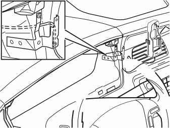
- Route the cable to the handset holder in the hole behind the combined instrument panel so that the handset holder can be positioned.
Routing the wiring for the handset holder
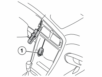
- Route the cable from the handset holder (1) through the hole behind the combined instrument panel into the centre console. Continue down along the left-hand air duct and out into the space where the climate control assembly was located.
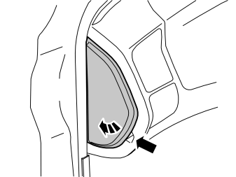
- Pry off the rear edge of the panel on the left-hand end of the dashboard. Twist out the panel. Remove the panel.
Illustration A
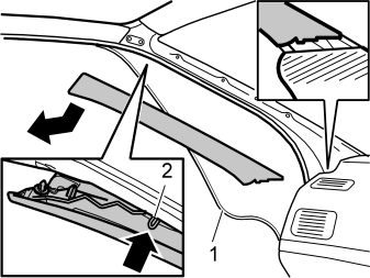
Illustration B
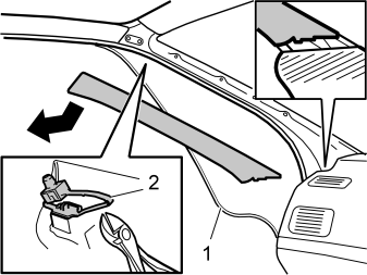
- Detach the door sill moulding (1) at the panel
- Pull the panel straight inwards into the car
- Lift up the panel
- Cut off the safety clip (2) illustration 18A or unhook the safety hook (2) illustration 18B, depending on the version.
Примечание: Ensure that the guide lugs on the panel do not scratch the dashboard.
- Turn the safety clip a quarter turn. Remove the safety clip.
Примечание: There are two types of mounting for the A-post panel nearest the headlining - safety hooks or safety clips.
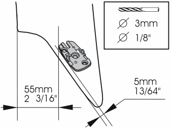
- Take the mounting plate from the kit. Position the mounting plate on the top end of the A-post panel, parallel with the top edge. See the illustration. If the microphone is already installed in the mounting plate, remove it. It is secured by two hooks on the long sides
- Mark out and drill the holes for the mounting plate. Use a 3 mm (1/8”) diameter drill bit
- Remove any swarf.
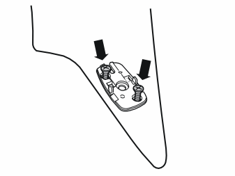
- Install the mounting plate on the A-post panel using two screws from the kit.
Осторожно: The inflatable curtain (IC) is located inside the A-post panel. It is important to file off the screws securing the mounting plate if necessary, so that they just fit through the panel.
- Check how much of the screws protrudes on the reverse. Unscrew the screws. File off the screws to the correct length
- Reinstall the screws.
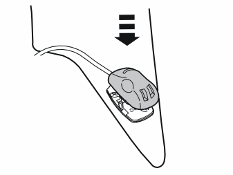
- Press the microphone from the kit into place on the mounting plate.
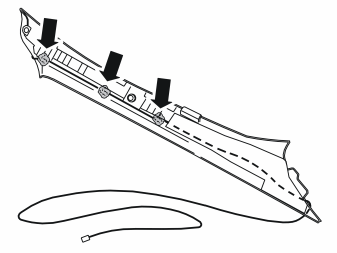
- Route the microphone cable on the inside of the A-post panel. Secure the cable using pieces of butyl tape.
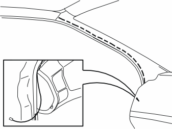
- Install a new safety clip, or hook the safety hook into the panel.
Примечание: It is important to use a new safety clip when installing.
- Press the panel into place
- Reinstall the weatherstrip in the door opening.
Примечание: It is important to install the safety clip/hook and panel correctly so that the IC system is not affected.
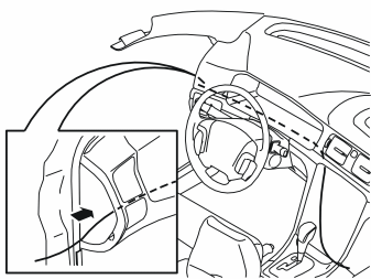
- Insert a wire coil in the end of the dashboard, through the space behind the combined instrument panel and into the centre console.
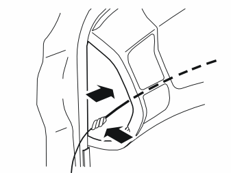
- Tape the microphone cable connector to the wire coil. Route the whole cable to the centre console
- Disconnect the connector from the wire coil. Ensure that the microphone cable is positioned so that there is no risk of it catching or rubbing
- Reinstall the end panel
- Reinstall the combined instrument panel. Ensure that the cable to the handset holder is not trapped
- Reinstall the combined instrument panel surround. Locate the cable and the bracket in the cut outs
- Reinstall the rubber seal in the upper steering column cover.
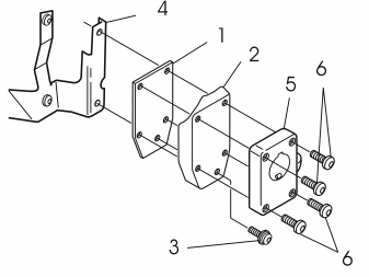
- Install the bracing plate (1) and the cover (2) on the bracket (4). Use the screw (3) from the kit. Do not tighten fully yet
- Secure the handset holder mounting plate (5) using the screws (6) from the kit
- Tighten the screw (3).
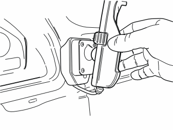
- Press the handset holder into the mounting plate until a click is heard.
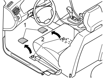
- Remove the cover (1) and the screws (2) for the front mountings in the driver's seat. There are new screws in the kit.
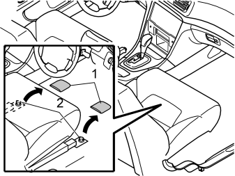
Applies to S60 with an audio amplifier
- Remove the covers (1) from the front mounting screws for the right-hand seat
- Remove the screws (2) from the seat base
- Tip the seat back.
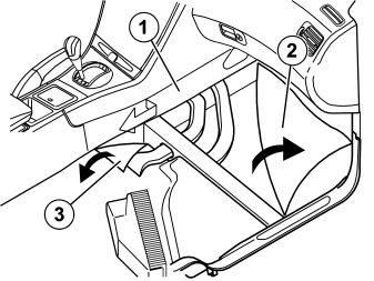
Applies to S60 with an audio amplifier
- Remove the panel (1) on the right-hand side of the centre console. Turn the clip at the rear edge of the panel through 90°. Pull the rear edge of the panel outward and backward
- Detach the carpet (2) by the front left mounting for the right-hand seat. Pull the carpet forward and to the right
- Fold the rear mat (3) backwards at an angle.
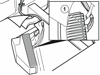
Applies to S60 with an audio amplifier
- Disconnect the grey connector (1) from the amplifier.
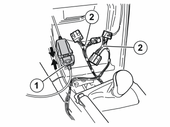
Applies to the S60 and V70 without audio amplifiers
- Take the black joint cable (from the kit) to the handset holder (1). Connect it to the cable from the handset holder that was routed down earlier
- Take the large cable harness from the kit. Position the grey and green connectors (2) in the space where the radio will be located.
Applies to the S60 with an amplifierIllustration A
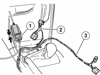
- Take the black joint cable (from the kit) to the handset holder (1). Connect it to the cable from the handset holder that was routed down earlier
- Take the large cable harness from the kit. Position the green connectors (2) in the space where the radio will be located
- Route the cable with the grey connectors (3) on the right-hand side inside of the centre console at the air ducts, alongside the cable harness for the amplifier and down to the amplifier (Illustration B).
Illustration B
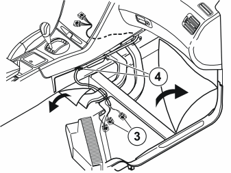
- Clamp the wiring at the positions (4). Use tie straps from the kit.
Applies to S60 with an audio amplifier
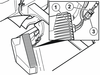
- Connect the grey male terminal (1) in the pre-routed cable harness to the amplifier
- Connect the grey connector (2) that was disconnected from the amplifier to the remaining terminal (3) in the pre-routed cable harness.
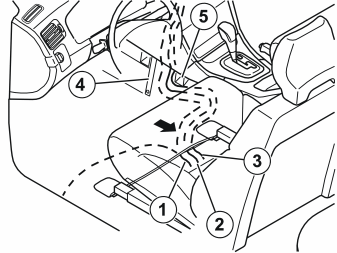
- Route the following three cable harnesses down:
- Route these cable harnesses inside the carpet, between the stay for the centre console (4) and the front air duct (5). Continue backwards, then in front of the front mounting for the driver's seat and out through the carpet joint under the seat.
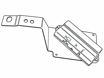
- Take the bracket, screws and hands free box from the kit
- Tighten the hands free box to the bracket as illustrated.
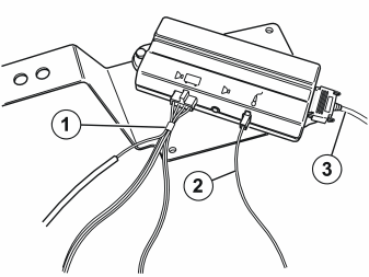
- Connect the routed cable harnesses to the hands free box:
Applies to cars with accessory electronic modules (AEM)
- Route the long cable, secured at the cable harness to the radio, under the carpet on the driver's side and out to the door sill. This will be connected to the accessory electronic module (AEM) later.
Applies to cars without an accessory electronic module (AEM)
- Insulate and hide the long cable that is secured at the cable harness to the radio. It will not be used.
Cable routing and connection to the accessory electronic module (AEM) for the V70
Примечание: Points 38-48 apply to the V70
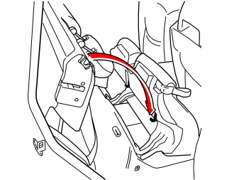
- Fold the rear backrests forward.
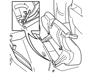
- Fold the rear seat cushions forward.
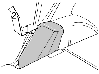
- Remove both the side cushions. First pull the upper edge of the cushions backwards. Then lift the cushions upwards.
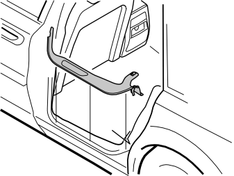
- Remove the sill trim panel at the left rear door.
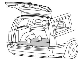
- Remove both the floor hatches. First lift the rear edges of the floor hatches slightly. Then pull the hatches backwards from their mountings.
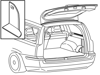
- Remove the foldable panels on the left and right-hand sides of the cargo compartment.
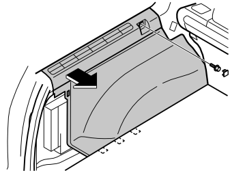
- Remove the left-hand side panel. First remove the cover and the screw at the front edge of the panel
- Pull the top of the panel out until the clips release
- Fold the panel inwards. Lift the panel out
- Repeat the operation on the right-hand side.
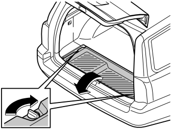
- Remove the storage box from under the rear floor hatch by turning the clip on the left and right-hand sides 90°. Lift out the box.
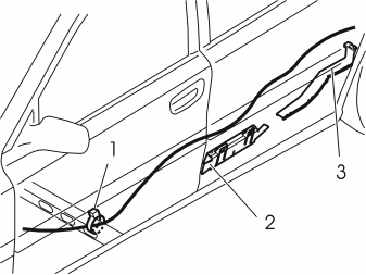
- Take the foam tape from the kit. Install the tape on the section of the long single cable to be routed under the sill trim panel for the tailgate. This is to prevent rattling
- Take the long single cable that was routed with the cable harness from the radio. Route the cable under the carpet to the left-hand side of the car
- Clamp the single cable at the existing cable harness on the left-hand side of the cross member. Use a tie strap (1)
- Route the cable inside the carpet and under the cable ducts (2) and (3) along the left-hand side of the car towards the cargo compartment. Ensure that the cable is securely pressed down between the sills and carpets
- Route the cable under the existing wiring and the connectors by the cable duct (3).
Illustration A
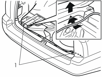
- Route the cable along the left rear wheel arch to the rear end of the left floor support
- Remove the outer screws (1) in the tailgate sill trim panel
- Pull up the tailgate sill trim panel on the left-hand side. Insert the cable between the floor support and the sill trim panel
- Slide the cable as far in towards the rear cross member as possible. Ensure that the cable is not trapped
- Route the cable along the existing cable harness by the rear cross member and over to the right-hand side of the car. Insert the cable between the sill trim panel and the floor support in the same way as on the left-hand side.
Illustration B
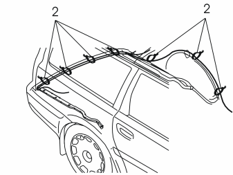
- Clamp the cable using tie straps (2)
- Press the sill trim panel back into place. Reinstall the two screws.
- Finish routing the cable. See points 57-65 (this procedure is the same for both models).
Cable routing and connection to the accessory electronic module (AEM) for the S60
Примечание: Points 49-61 only apply to the S60, while points 62-70 apply to both the S60 and the V70
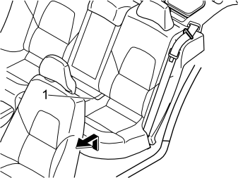
- Remove the left seat cushion (1) from the rear seat. First pull the front edge of the seat cushion up. Pull the cushion forwards. Then lift the seat cushion out.
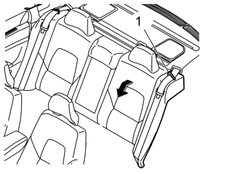
- Fold forward the left-hand rear backrest
- Remove the seat belt from the guide (1).
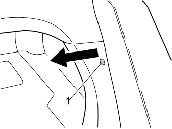
- Remove the clip (1) at the side of the left-hand side cushion
- Pull out the top edge of the left front panel in the cargo compartment to access the upper catch for the side cushion.
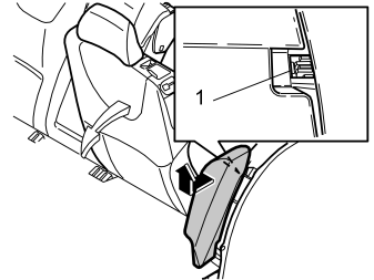
- Remove the left-hand side cushion. First press in the catches (1) at the top of the reverse of the side cushion. Pull the cushion out slightly
- Grasp the cushion using both hands. Twist anti-clockwise until the catches on the inside release
- Remove the side cushion. First pull out the top of the side cushion. Then pull upwards.
- Remove the sill trim panel at the left rear door.
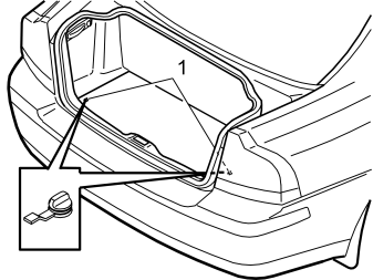
- Remove the cargo compartment carpet at the rear edge. First turn the two knobs (1) 90°.
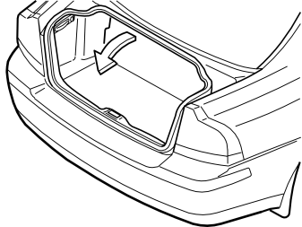
- Pull up the front of the cargo compartment carpet. Fold the front half back over the rear half of the cargo compartment carpet.
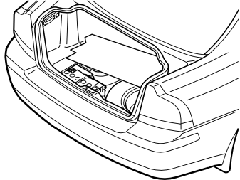
- Slide the entire cargo compartment carpet forward slightly. Twist slightly to remove the carpet through the tailgate opening
- Remove the cargo compartment carpet.
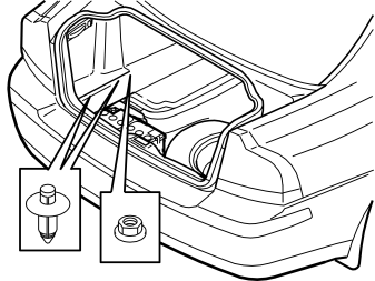
- Press the centres of the clips at the bottom of the folding side panel on the left-hand side. Press the clips until a click is heard
- Remove the two clips
- Remove the plastic nut at the front edge of the side panel
- Repeat the operation on the right-hand side.
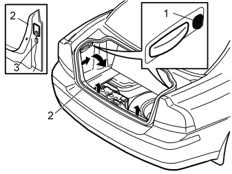
- Turn the handle (1) on the right and left-hand sides. Turn the handle through 90°.
- Fold the side panels down. Lift the panels out
- Pull the tailgate sill trim panel (2) forwards on the right and left-hand sides until the clips on each side release. Carefully pull the panel. Pull with some force as it is tightly secured
- Remove the wiring (3) for the cargo compartment lighting
- Pull the sill trim panel straight up until the four clips on the underneath release. Remove the sill trim panel.
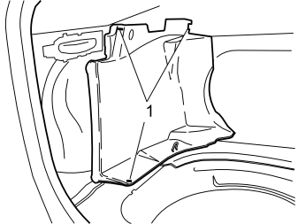
- Remove the clips (1) from the left front side panel in the cargo compartment. Remove the panel.
- Take the long single cable that was routed with the cable harness from the radio. Route the cable under the carpet to the left-hand side of the car
- Clamp the single cable at the existing cable harness on the left-hand side of the cross member. Use a tie strap (1)
- Route the cable inside the carpet and under the cable ducts (2) and (3) along the left-hand side of the car towards the cargo compartment. Ensure that the cable is securely pressed down between the sills and carpets
- Route the cable under the existing wiring and the connectors by the cable duct (3).
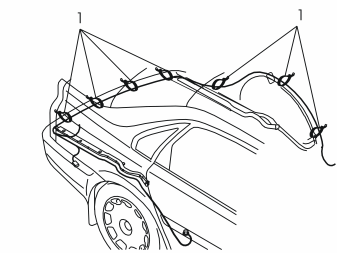
- Route the cable along the left-hand rear wheel arch to the rear cross member
- Continue to route the cable along the rear cross member over to the rear edge of the right-hand rear wheel arch
- Clamp the cable along the existing cable harnesses using tie straps (1).
Applies to the S60 and V70
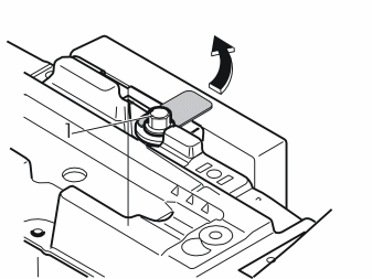
- Slacken off the screw (1) a few turns in the lock facing for the accessory electronic module (AEM) behind the right wheel arch
- Pull the lock facing out to the right. Remove the lock facing.
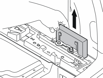
- Lift the accessory electronic module (AEM) out of the bracket.
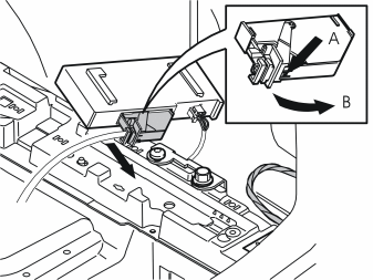
- Disconnect the large connector from the accessory electronic module (AEM). First press in the catch (A). Pull the black locking handle (B) in the direction of the arrow until a click is heard
- Disconnect the connector from the accessory electronic module.
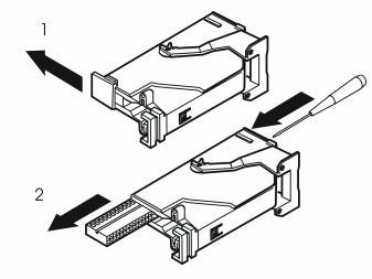
- Remove the black catch holding the black switch in place in the connector by pulling in the direction of the arrow
- Remove the black switch. Insert a pointed object in the hole on the other end of the connector. Press the switch out.
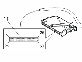
- Connect the pre routed cable to terminal 11 of the accessory electronic module (AEM) connector.
Примечание: The number markings can be found on the top and bottom of the black switch. However, the markings are extremely small so be careful when installing the cable.
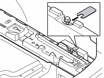
- Reinstall the black switch in the connector. Lock into place using the catch
- Press the connector into the accessory electronic module. Secure the connector using the black lock handle
- Reinstall the accessory electronic module (AEM). Secure any excess wiring
- Reinstall the lock facing above the accessory electronic module (AEM). Tighten the screw. Tighten to 10 Nm (8 lbf.ft.).
Installing the hands free box
Подсказка: Install the aerial according to the separate Installation Instructions.
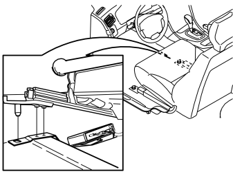
- Tip the driver's seat back slightly
- Position the hands free box and the bracket with the mounting over the screw hole in the right front mounting for the driver's seat
- Fold the seat down towards the mountings. Check that the hands free box bracket is positioned under the seat rail
- Route all excess cable in under the carpet.
Примечание: Ensure that the none of the wiring is trapped.
- Tighten the front edge of the seat using two new screws from the kit. Tighten to 40 Nm (30 lbf. ft.).
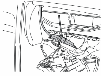
- Take a tie strap from the kit. Clamp the connectors to the handset holder at the larger cable harness to the radio. Ensure that the connectors are properly secured and do not rattle.
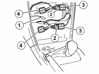
Applies to the S60 and V70 without audio amplifiers
- Connect the switch from the handset holder extension cable (1) to the car aerial. The aerial is installed according to a separate Installation Instruction
- Connect the new, large cable harness connectors (2) to the corresponding connectors removed from the radio (3)
- Connect the connectors (4) to the radio
- Connect any other connectors removed from the radio
- Reinstall the radio.

Applies to S60 with an audio amplifier
- Connect the switch from the handset holder extension cable (1) to the car aerial. The aerial is installed according to a separate Installation Instruction
- Connect the connector (2) for the new large cable harness to the connector (3) that was disconnected from the radio
- Connect the connector (4) to the radio
- Connect any other connectors removed from the radio
- Reinstall the radio.
Finishing work
Reinstall:
- the side panels on the centre console
- the dashboard environmental panel
-
the panel around the gear selector lever.
-
Use two new screws from the kit. Tighten the right hand seat. Tighten to 40 Nm (30 lbf. ft.).
Reinstall:
- the covers for the screws for the front seats
- the bracket for the loudspeaker grille
- the loudspeaker grille.
Applies to cars with a storage compartment
- Install the storage compartment. Tighten using the four screws
- Reinstall the surround for the storage compartment.
Applies to cars with a centrally mounted loudspeaker
- Connect the connector to the loudspeaker
- Reinstall the loudspeaker and bracket. Tighten the loudspeaker and bracket using the four screws
- Reinstall the loudspeaker grille.
Applies to cars with RTI (road traffic information)
- Connect the connector to the RTI display (and to the centrally mounted loudspeaker if applicable)
- Reinstall the RTI unit and holder. Reinstall the centrally mounted loudspeaker where applicable. Tighten using the four screws
- Reinstall the panel.
Applies to the V70
- Reinstall the storage box in the cargo compartment
- Reinstall the floor hatches in the cargo compartment
- Fold the backrest and left-hand seat cushion back into position.
Applies to the S60
- Reinstall the cargo compartment carpet
- Reinstall the rear seat cushion.
Applies to the S60/V70
- Reinstall the panels in the cargo compartment
- Reinstall the side cushion
- Reinstall the sill trim panels on the left-hand side
- Turn the ignition key to position II
- Reconnect the battery negative lead
- Program the software according to the service information in VIDA.
Обсуждение и оценка
0Пока нет комментариев. Будьте первым.