Применимость
| Модель | Двигатель | Год |
|---|---|---|
| S40 (04-) | — | 2004–2008 |
| V50 | — | 2004–2008 |
Примечание: This accessory requires software unique to the car.
Примечание: - Steps 1–50 apply to left-hand drive cars
- Steps 51-96 apply to right-hand drive cars
Preparations for left-hand drive car
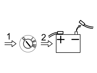
- Turn the ignition key to position 0.
- Disconnect the battery negative lead.
Примечание: Wait at least five minutes before disconnecting the connectors or removing other electrical equipment.
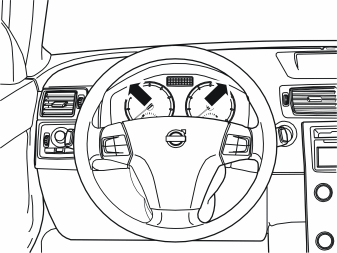
- Position the steering wheel in its lowest and rearmost position.
- Remove the two screws from the surround for the combined instrument panel.
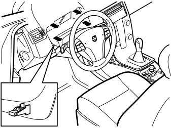
- Pull off the surround starting at the lower edge and then at the upper edge. The surround is secured by a clip at each side of the lower edge. Place the surround to one side.
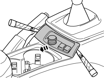
- Carefully pry off the panel at the rear edge of the centre console. Use a weatherstrip tool. The panel is secured by a catch on each of the short sides.
- Move the panel to the side to access the two screws underneath.
- Remove the two screws.
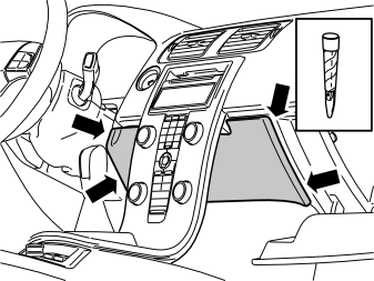
- Open the glove compartment.
- Carefully pry off the panel inside the centre console. Use a plastic weatherstrip tool. The panel is secured by two clips on each of the short sides.
- Pull the panel downwards.
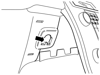
- Carefully press in the air quality sensor so it releases from its holder on the back side of the glove compartment.
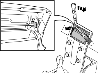
- Detach the surround around the display and the media player: Press in the catch at the edge of the media player cover. Use a small screwdriver. Carefully pry off the surround at the corner. Use a plastic weatherstrip tool.
Примечание: Do not damage the panel and dashboard.
Repeat the operation on the other side.
Подсказка: If the other side does not detach, press the detached side into position again and repeat the procedure, beginning from the other side.
- Fold the surround backwards. Remove by pulling upwards.
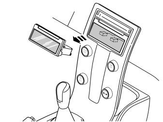
- Press out the display module (1) from the reverse of the centre console. Use both hands and press straight back.
- Disconnect the two connectors. Put the display to one side.
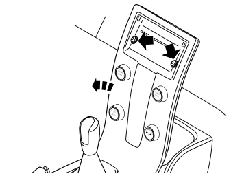
- Remove the two screws holding the centre console to the dashboard.
- Remove the connector on the reverse of the dashboard environment panel.
- Remove the centre console from the dashboard and tunnel console.
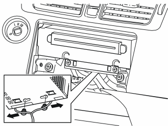
- Remove the two clips securing the cables to the media player by first pressing them to the sides and then pulling them away downwards.
Примечание: Be careful with the optic cables so that they are not bent or stretched.
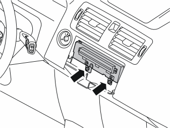
- Remove the two screws from the bottom of the media player.
- Pull out the media player. Disconnect the connector on the reverse side.
Примечание: Note how the wiring is packed on the reverse. The fibre optic cables are easily damaged and must not be bent to a radius less than 25 mm (1“).
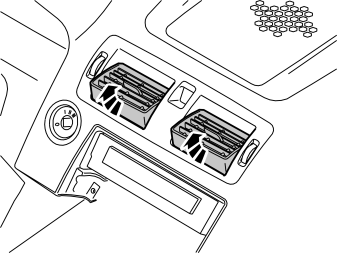
- Angle up both air vents.
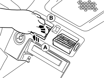
- Grip the air vent, press it out and pull it up.
- Do the equivalent to the other air vent.
Illustration A
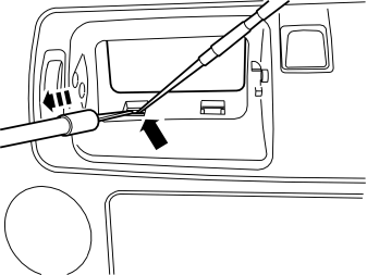
- Insert a scriber and push up one of the catches in the lower edge of the air vents' housing.
- Insert the tool part no. 9995919 in the space which is opened and pull out until the catch releases.
- Repeat this until all catches in the lower edge have released.
Illustration B
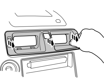
- Grip the ends of the housing and pull out until all catches on both the top and bottom are fully free from the inside of the dashboard. If necessary, use a weatherstrip tool to prize out the ends of the housing.
Примечание: Do not damage the dashboard.
Примечание: Pull alternately on the right and left-hand sides, otherwise the edge of the housing will crack where it enters the air ducts on the inside. The housing is secured firmly so force will be required to release it.
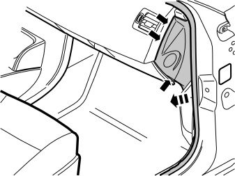
- Remove the panel on the right-hand and left-hand ends of the dashboard. Carefully pry off the panel until the three clips release. Use a weatherstrip tool.
Примечание: Do not damage the dashboard.
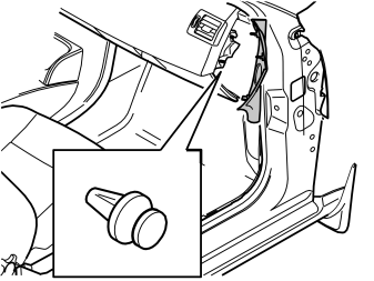
- Remove the clip holding the nozzle for the air duct on the right-hand and left-hand sides.
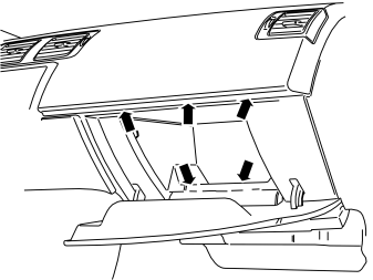
- Remove the five screws in the opening for the glove compartment.
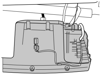
- Remove the front section of the glove compartment by pulling backwards until the two clips at the upper edge release. Disconnect the two connectors from the top.
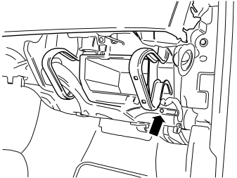
- Remove the screw for the vent on the right-hand side. Pull off the vent to the right. Place to one side.
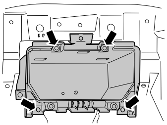
- Remove the three screws to the inner section of the glove compartment and pull it out. Place it to one side.
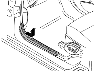
- Remove the sill trim panel from the left-hand and right-hand front doors. First pull off the front edge of the sill trim panel so that the clip there releases. Then continue backwards until the remaining clips on the underneath have released.
- Unhook the sill trim panel from the B-post panel.
Illustration A
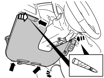
- Remove the three screws in the soundproofing panel on the left-hand side.
- Push the carpet on the left-hand side of the centre console to one side.
- Carefully pry off the soundproofing panel from the top edge of the dashboard. Use a weatherstrip tool. The panel is secured by two clips at the top edge.
Illustration B
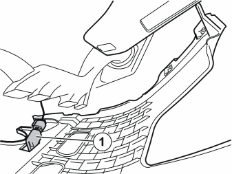
- Remove the soundproofing panel. First disconnect the connectors for the lighting (1).
Installing the telephone holder
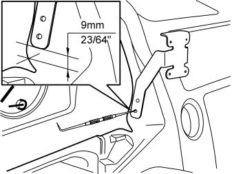
- Fit the support legs of the bracket from the kit into the socket for the surround of the combined instrument panel and in the left-hand air vent.
- Position the left-hand support leg of the bracket as illustrated. The front edge of the support leg must be parallel with the edge in the cut-out in the dashboard and the measurement to the bottom edge of the support leg must be taken from the centre of the radius.
- Mark out the holes to be drilled for the mounting.
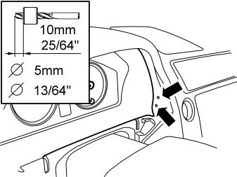
- Drill out the holes using a Ø5 mm (13/64') diameter drill bit. Use a 10 mm (25/64') drill stop to prevent damaging the components on the inside.
- Remove any swarf.
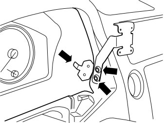
- Secure the left-hand support leg of the bracket to the dashboard using two screws and the mounting plate (located on the inside) from the kit.
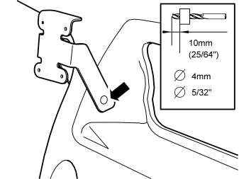
- Drill out the hole for the right-hand support leg with a Ø4 mm (5/32') diameter bit.
- Take a screw from the kit and secure the right-hand support leg.
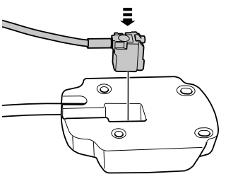
- Take the mounting plate and short antenna cable with blue connector from the kit.
- Press in the antenna cable's blue connector on the rear of the mounting plate.
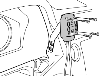
- Take the mounting plate and four screws (l = 16mm) from the kit. Secure the mounting plate in the installed bracket.
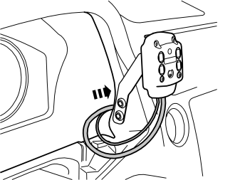
- Insert the two connectors on the top of the ignition switch, on the right-hand side of the combined instrument panel, and then down in the dashboard. There is not much space by the ignition switch, so be careful with the cables there.
Installing the microphone
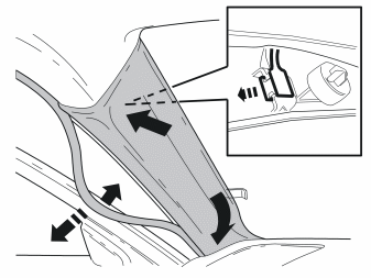
- Remove the weatherstrip for the door at the A-post.
- Pull off the panel from the A-post. The panel is secured by three clips.
- Lift the panel upwards and outwards.
- Unhook the clip nearest the roof.
- Remove the panel.
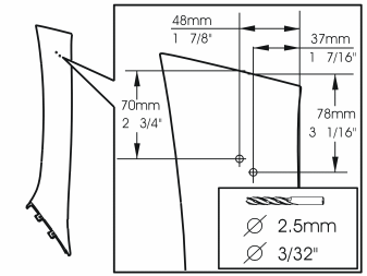
- Mark out and drill the holes for the mounting plate. Use a Ø2.5 mm (3/32') diameter drill bit as illustrated.
- Remove any swarf.
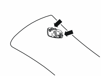
- The microphone is secured to the mounting plate (if applicable). Remove the microphone secured with two mounting hooks by the long sides.
- Install the mounting plate on the A-post panel using two screws from the kit.
Осторожно: The inflatable curtain (IC) is located inside the A-post panel. It is important to file off the screws securing the mounting plate if necessary, so that they just fit through the panel.
- Check how much of the screws protrudes on the reverse. Unscrew the screws. File off the screws to the correct length
- Reinstall the screws.
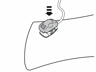
- Press the microphone from the kit into place on the mounting plate.
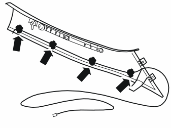
- Route the microphone cable along the inside of the A-post. Secure it with pieces of butyl tape where it folds over the edge of the panel and continue along the front edge as illustrated.
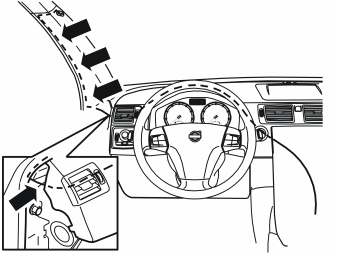
- Reinstall the A post panel.
- Insert the cable for the microphone through the left end of the dashboard.
- Continue to route the cable above the combined instrument panel to the cable for the telephone holder by the ignition key.
- Now route the cable in the same way as the cable for the telephone holder.
- Reinstall the rubber strip in the door opening.
Cable routing
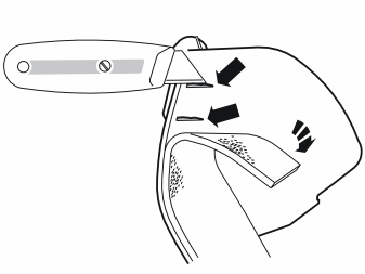
- Push the felt tape on the right-hand side of the surround to one side.
- Cut off the two tabs.
- Re-apply the tape.
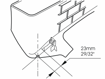
- File a groove in the combined instrument panel surround for the cable for the telephone holder, as illustrated.
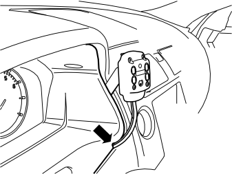
- Reinstall the combined instrument panel surround. Ensure that the telephone holder cable is positioned in the cut-out.
- Adjust the cable length between the telephone holder and surround.
- Reinstall the housing and air vents.
Примечание: When the air vents' housing is reinstalled, make sure that the protruding parts on the right-hand end of the housing do not damage the dashboard.
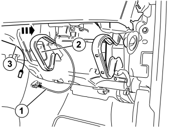
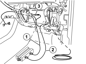
- Route the long cable (1) in the secured mounting plate, inside the panel, over the air duct (2) and forward. Route the cable out where the inner part of the glove compartment was fitted.
- Allow the cable (3) to the antenna to remain in the centre of the dashboard.
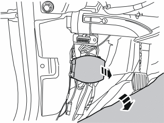
- Push the carpet on the left-hand side, at the front edge of the left-hand front door sill, to one side.
- Remove the cover for the inside connector bridge.
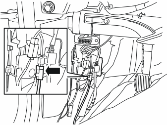
- Take the short telephone antenna cable from the kit. Connect the cable to the corresponding connector in the connector bridge.
- Reinstall the cover for the connector bridge. Fold the carpet back into position.
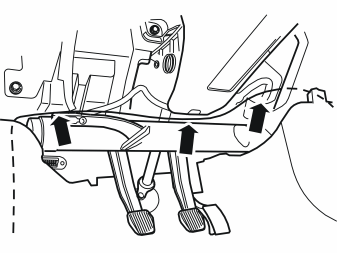
- Pull the antenna cable up inside the carpet in front of the collision member, by the left mounting in the bodywork. Then route the cable to the right along the air duct and into the centre console to the connector from the telephone holder.
- Secure the antenna cable at the air duct to prevent damage. Use three tie straps from the kit.
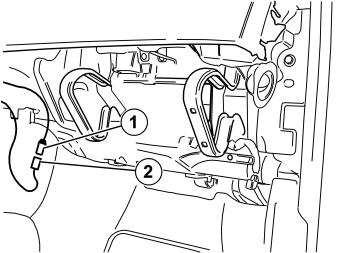
- Connect the short antenna cable (1) from the mounting plate to the newly routed antenna cable (2).
- Wrap the newly attached connectors with foam tape from the kit to prevent rattling. Conceal the excess cable in the dashboard and inside the carpet.
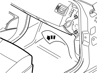
Applies to cars without a passenger compartment connector socket
- Push the floor carpet to one side in order to route the cable harnesses toward the rear of the car.
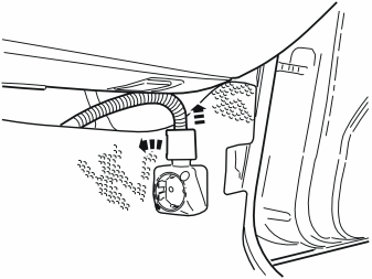
Applies to cars with a passenger compartment connector socket
- Remove the locking sleeve over the cable splice in the passenger compartment connector socket.
- Disconnect the cable from the passenger compartment connector socket.
- Remove the passenger compartment connector socket from its bracket.
- Push the floor carpet to one side in order to route the cable harnesses toward the rear of the car.
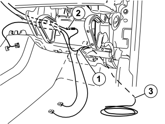
- Take the large cable harness (1) from the kit. Route the long solid core wire with the black and the white connector the same route as the cable from the mounting plate. The two large grey connectors must remain in the centre of the dashboard.
- Route the cable (2) for the microphone in the same way.
- Route the long solid core wire (3) in the cable harness in the front edge of the fuse holder, down and inside the floor carpet, and out at the right-hand front door sill.
Installing the Phone Module (PHM)
- Take the control module from the kit and connect the cables in accordance with the following:
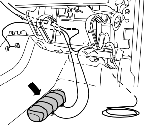
- Wrap the control module with foam tape from the kit to prevent rattling.
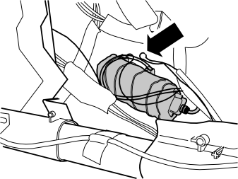
- Fit the newly connected control module furthest in on the left-hand side against the cowl. Fit it so that it cannot detach and so that there is no risk of it being trapped by the inner part of the glove compartment when this is reinstalled.
- Collect all excess cable and place it on the left-hand side as well.
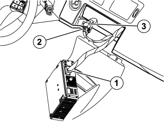
- Connect the grey connector (1) in the routed cable harness to the corresponding socket in the media player.
- Connect the grey connector (2) in the routed cable harness to the grey connector (3) which was detached from the media player.
- Plug the remaining connectors which where detached into the media player.
- Reinstall the media player and secure it.
Preparations for right-hand drive car
- Turn the ignition key to position 0.
- Disconnect the battery negative lead.
Примечание: Wait at least five minutes before disconnecting the connectors or removing other electrical equipment.
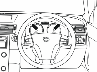
- Position the steering wheel in its lowest and rearmost position.
- Remove the two screws from the surround for the combined instrument panel.
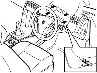
- Pull off the surround starting at the lower edge and then at the upper edge. The surround is secured by a clip at each side of the lower edge. Place the surround to one side.
- Carefully pry off the panel at the rear edge of the centre console. Use a weatherstrip tool. The panel is secured by a catch on each of the short sides.
- Move the panel to the side to access the two screws underneath.
- Remove the two screws.
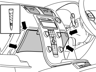
- Open the glove compartment.
- Carefully pry off the panel inside the centre console. Use a plastic weatherstrip tool. The panel is secured by two clips on each of the short sides.
- Pull the panel downwards.
- Detach the surround around the display and the media player: Press in the catch at the edge of the media player cover. Use a small screwdriver. Carefully pry off the surround at the corner. Use a plastic weatherstrip tool.
Примечание: Do not damage the panel and dashboard.
Repeat the operation on the other side.
Подсказка: If the other side does not detach, press the detached side into position again and repeat the procedure, beginning from the other side.
- Fold the surround backwards. Remove by pulling upwards.
- Press out the display module (1) from the reverse of the centre console. Use both hands and press straight back.
- Disconnect the two connectors. Put the display to one side.
- Remove the two screws holding the centre console to the dashboard.
- Remove the connector on the reverse of the dashboard environment panel.
- Remove the centre console from the dashboard and tunnel console.
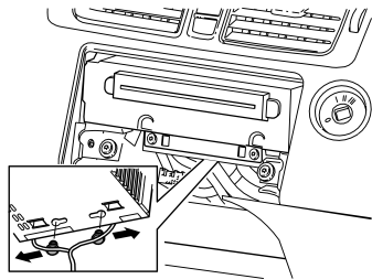
- Remove the two clips securing the cables to the media player by first pressing them to the sides and then pulling them away downwards.
Примечание: Be careful with the optic cables so that they are not bent or stretched.
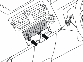
- Remove the two screws from the bottom of the media player.
- Pull out the media player. Disconnect the connector on the reverse side.
Примечание: Note how the wiring is packed on the reverse. The fibre optic cables are easily damaged and must not be bent to a radius less than 25 mm (1“).
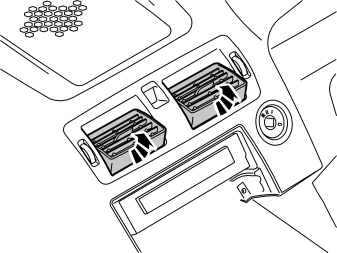
- Angle up both air vents.
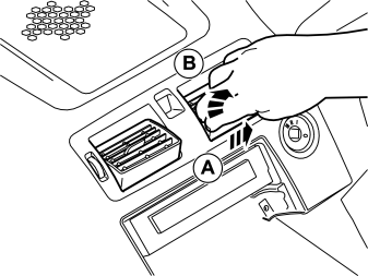
- Grip the air vent, press it out and pull it up.
- Do the equivalent to the other air vent.
Illustration A
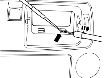
- Insert a scriber and push up one of the catches in the lower edge of the air vents' housing.
- Insert the tool part no. 9995919 in the space which is opened and pull out until the catch releases.
- Repeat this until all catches in the lower edge have released.
Illustration B
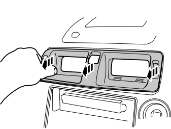
- Grip the ends of the housing and pull out until all catches on both the top and bottom are fully free from the inside of the dashboard. If necessary, use a weatherstrip tool to prize out the ends of the housing.
Примечание: Do not damage the dashboard.
Примечание: Pull alternately on the right and left-hand sides, otherwise the edge of the housing will crack where it enters the air ducts on the inside. The housing is secured firmly so force will be required to release it.
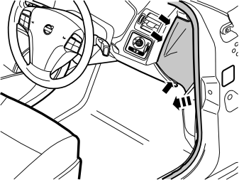
- Remove the panel on the right-hand end of the dashboard. Carefully pry off the panel until the three clips release. Use a weatherstrip tool.
Примечание: Do not damage the dashboard.
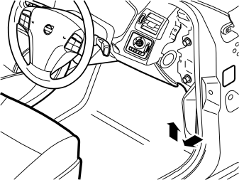
- Remove the sill trim panel from the right-hand front door. First pull off the front edge of the sill trim panel so that the clip releases. Then continue backwards until the remaining clips on the underside have released.
- Unhook the sill trim panel from the B-post panel.
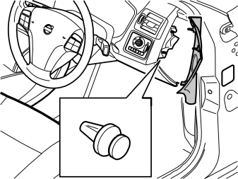
- Remove the clip holding the nozzle for the air duct on the right-hand side.
Illustration A
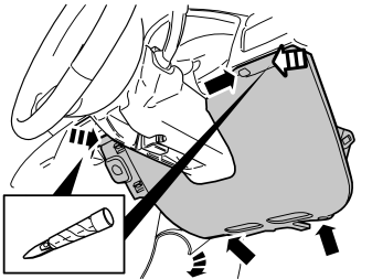
- Remove the three screws in the soundproofing panel on the right-hand side.
- Push the carpet on the right-hand side of the centre console to one side.
- Carefully pry off the soundproofing panel from the top edge of the dashboard. Use a weatherstrip tool. The panel is secured by two clips at the top edge.
Illustration B
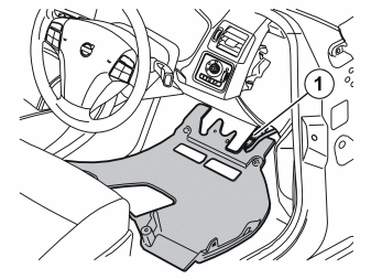
- Remove the soundproofing panel. First disconnect the connector for the lighting (1).
Installing the telephone holder
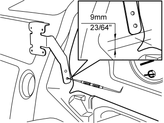
- Fit the support legs of the bracket from the kit in the socket for the surround of the combined instrument panel and in the right-hand air vent.
- Position the right-hand support leg of the bracket as illustrated. The front edge of the support leg must be parallel with the edge in the cut-out in the dashboard and the measurement to the bottom edge of the support leg must be taken from the centre of the radius.
- Mark out the holes to be drilled for the mounting.
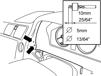
- Drill out the holes using a Ø5 mm (13/64') diameter drill bit. Use a 10 mm (25/64') drill stop to prevent damaging the components on the inside.
- Remove any swarf.
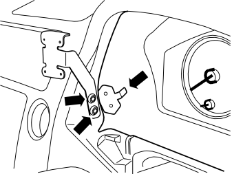
- Secure the right-hand support leg of the bracket to the dashboard using two screws and the mounting plate (located on the inside) from the kit.
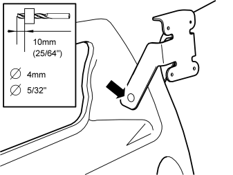
- Drill out the hole for the left-hand support leg with a Ø4 mm (5/32') diameter bit.
- Take a screw from the kit and secure the left-hand support leg.
- Take the mounting plate and short antenna cable with blue connector from the kit.
- Press in the antenna cable's blue connector on the rear of the mounting plate.
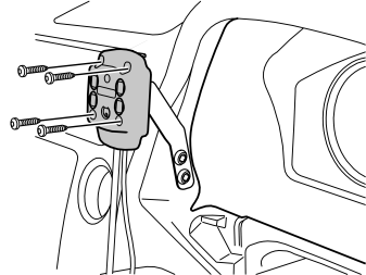
- Take the mounting plate and four screws (l = 16mm) from the kit. Secure the mounting plate in the installed bracket.
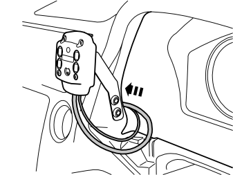
- Insert the two connectors on the underside of the ignition switch, on the left-hand side of the combined instrument panel, and then down in the dashboard.
Installing the microphone
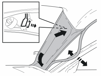
- Remove the weatherstrip for the door at the A-post.
- Pull off the panel from the A-post. The panel is secured by three clips.
- Lift the panel upwards and outwards.
- Unhook the clip nearest the roof.
- Remove the panel.
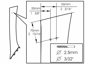
- Mark out and drill the holes for the mounting plate. Use a Ø2.5 mm (3/32') diameter drill bit as illustrated.
- Remove any swarf.
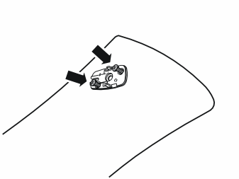
- The microphone is secured to the mounting plate (if applicable). Remove the microphone secured with two mounting hooks by the long sides.
- Install the mounting plate on the A-post panel using two screws from the kit.
Осторожно: The inflatable curtain (IC) is located inside the A-post panel. It is important to file off the screws securing the mounting plate if necessary, so that they just fit through the panel.
- Check how much of the screws protrudes on the reverse. Unscrew the screws. File off the screws to the correct length
- Reinstall the screws.
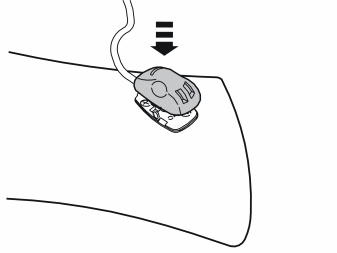
- Press the microphone from the kit into place on the mounting plate.
- Route the microphone cable along the inside of the A-post. Secure it with pieces of butyl tape where it folds over the edge of the panel and continue along the front edge as illustrated.
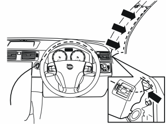
- Reinstall the A post panel.
- Insert the cable for the microphone through the right-hand end of the dashboard.
- Continue to route the cable above the combined instrument panel to the cable for the telephone holder by the ignition key.
- Now route the cable in the same way as the cable for the telephone holder.
- Reinstall the rubber strip in the door opening.
Cable routing
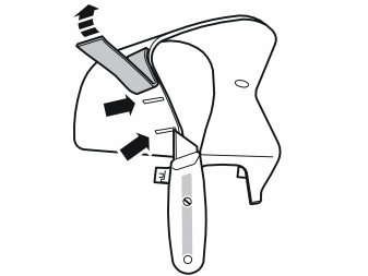
- Push the felt tape on the left-hand side of the surround to one side.
- Cut off the two tabs.
- Re-apply the tape.
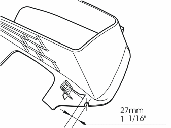
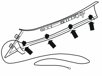
- File a groove in the combined instrument panel surround on the left-hand side for the cable to the telephone holder as illustrated.
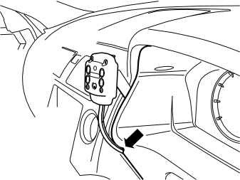
- Reinstall the combined instrument panel surround. Ensure that the telephone holder cables are positioned in the cut-out.
- Adjust the cable length between the telephone holder and surround.
- Reinstall the housing and air vents.
Примечание: When the air vents' housing is reinstalled, make sure that the protruding parts on the left-hand end of the housing do not damage the dashboard.
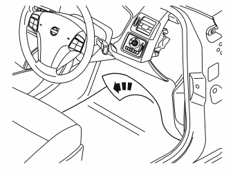
Applies to cars without a passenger compartment connector socket
- Push the floor carpet to one side in order to route the cable harness toward the rear of the car.
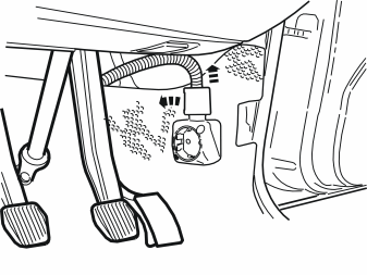
Applies to cars with a passenger compartment connector socket
- Remove the locking sleeve over the cable splice in the passenger compartment connector socket.
- Disconnect the cable from the passenger compartment connector socket.
- Remove the passenger compartment connector socket from its bracket.
- Push the floor carpet to one side in order to route the cable harnesses toward the rear of the car.
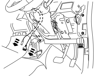
- Route the two cables from the secured mounting plate.
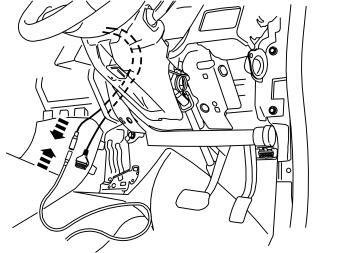
- Take the extension cable for the antenna from the kit and connect it to the short routed cable from the dashboard.
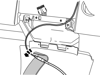
- Wrap the connectors with foam tape from the kit to prevent rattling.
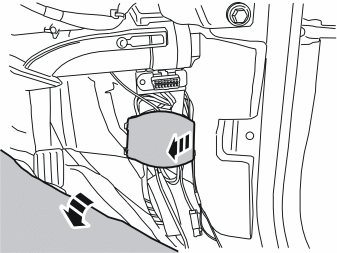
- Push aside the carpet on the right-hand side along the front edge of the opening for the front door.
- Pry off the cover to the connector bridge.
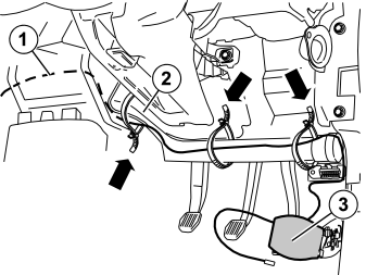
- Route the previously connected cable (1) to the antenna, from the mounting plate in the dashboard, to the right through the hole for the right-hand air duct (2). Continue this along to the impact member's right-hand mounting.
- Route it inside the mounting and down to the connector bridge (3).
- Secure it at the air duct with three tie straps from the kit.
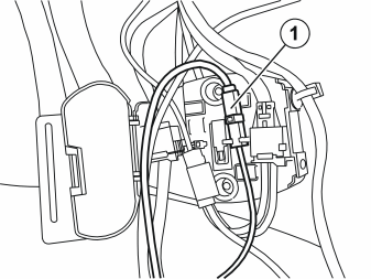
- Connect the routed antenna cable (1) to the corresponding cable in the connector bridge.
- Secure the cover over the contact bridge.
- Conceal the excess cable under the carpet.
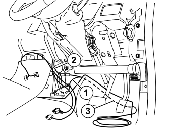
- Take the large cable harness (1) from the kit. Route the long solid core wire with the black and the white connector on the right-hand side of the centre console and down to the floor. The two large grey connectors must remain in the centre of the dashboard.
- Route the cable (2) for the microphone in the same way.
- Route the long solid core wire (3) in the cable harness down and inside the floor carpet, and out at the right-hand front door sill.
Installing the Phone Module (PHM)
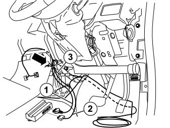
- Take the control module from the kit and connect the cables in accordance with the following:
- Clamp the cables at the existing cable harness on the right-hand side of the centre console using tie straps from the kit.
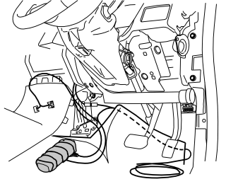
- Wrap the control module with foam tape from the kit to prevent rattling.
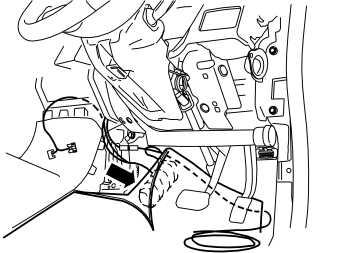
- Fit the newly connected control module furthest in on the right-hand side of the centre console, against the cowl under the carpet.
- Collect all excess cable and place it on the right-hand side as well.
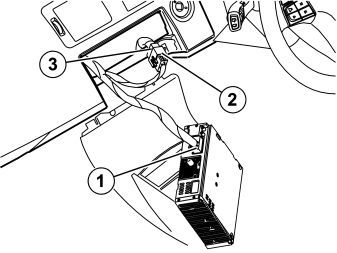
- Connect the grey connector (1) in the routed cable harness to the corresponding socket in the media player.
- Connect the grey connector (2) in the routed cable harness to the grey connector (3) which was detached from the media player.
- Plug the remaining connectors which where detached into the media player.
- Reinstall the media player and secure it.
Applies to the V50. Removing components in the cargo compartment
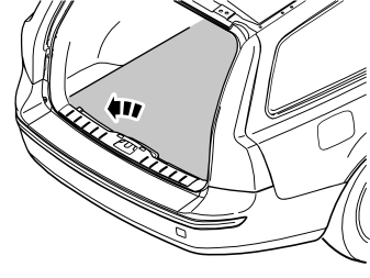
- Remove the cargo compartment carpet.
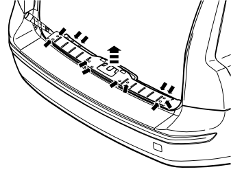
- Pry off the four external clips at the front edge/bottom edge of the sill trim panel on the tailgate.
- Pry up one of the corners of the sill trim panel so that the two clips at that end release. Use a weatherstrip tool.
- Pull up the sill trim panel so the remaining six clips release. Remove the panel.
- Detach the rubber strip where it covers the right-hand side panel in the boot opening.
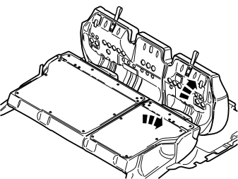
- Fold the seat cushion and backrest on the right-hand side of the rear seat forward.
- Grasp the upper edge of the right-hand side cushion. Pull the side cushion forward so that the clip on the reverse releases.
- Slide the side cushion up. Remove the side cushion.
- Remove the screw at the rear edge of the panel at the front/top of the right-hand side panel.
- Pull the panel upwards so that the four clips on the inside release. Remove the panel.
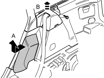
- Pull off the rubber strip at the rear of the opening for the right-hand rear door.
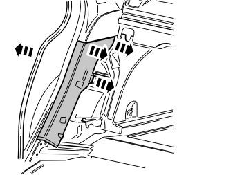
- Carefully pry off the lower panel on the C-post on the right-hand side. Carefully pry at the top edge. Use a plastic weatherstrip tool.
- Pull the panel on the C-post so that the two upper clips release. Then continue down until the last two clips release. Remove the panel on the C-post.
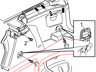
- Fold out the load securing eyelets on the right-hand side panel.
- Insert a scriber with an angled tip into the holes in the top of the covers (1). Turn the scriber so that the tip engages the reverse of the cover. Pull the cover off.
- Remove the screws in the load securing eyelets.
- Remove the screw (2) at the front/top edge of the side panel.
- Pull off the side panel at the top so that the two clips at the rear/bottom of the side window and the clip at the bottom of the D-post release.
- Disconnect the connector for the 12V socket, if present.
- Lift out the side panel.
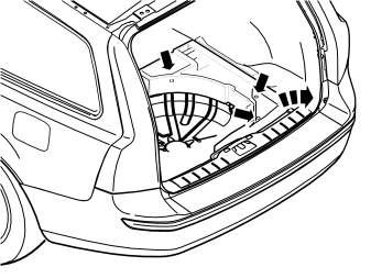
- Remove the right-hand floor support. First remove the three clips at the bottom of the compartment, then lift it up.
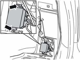
Applies to cars with reversing warning systems
- Remove the parking assistance system (PAS) behind the right-hand rear wheel arch. This is to access the lower clip for the insulation panel, and to later facilitate access to the accessory electronic module (AEM).
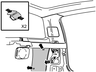
- Remove the insulation panel on the right-hand side. It is secured with two clips.
Applies to the S40. Removing components in the cargo compartment
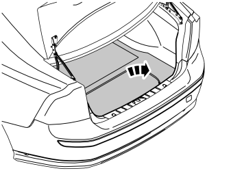
- Remove the cargo compartment carpet.
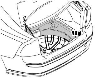
- Remove the upper floor support on the right-hand side, if applicable.
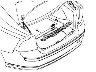
- Unscrew the two external clips at the front edge/bottom edge of the sill trim panel on the tailgate.
- Pry up one of the corners of the sill trim panel using a weatherstrip tool so that the two clips at that end release.
- Pull up the sill trim panel at the other end so that the remaining two clips release. Remove the sill trim panel.
- Detach the rubber strip where it covers the right-hand side panel in the boot opening.
- Fold the seat cushion and backrest on the right-hand side of the rear seat forward.
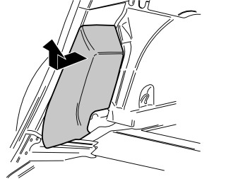
- Grasp the upper edge of the right-hand side cushion. Pull the side cushion forward so that the clip on the reverse releases.
- Slide the side cushion up. Remove the side cushion.
- Pull off the rubber strip at the rear of the opening for the right-hand rear door.
- Carefully pry off the lower panel on the C-post on the right-hand side. Carefully pry at the top edge. Use a plastic weatherstrip tool.
- Pull the panel on the C-post so that the two upper clips release. Then continue down until the last two clips release. Remove the panel on the C-post.
Illustration A
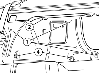
Illustration B
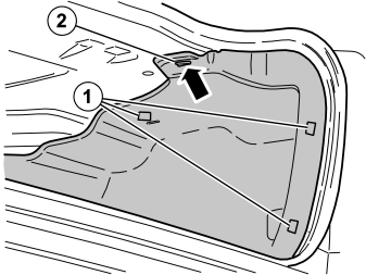
- Remove the five clips (1), in illustrations A and B holding the right-hand side panel in the bodywork.
- Unhook the front edge of the parcel shelf panel at the mounting (2), in illustration A. Pull the side panel away from the parcel shelf panel and the panel on the C-post.
- Unhook the side panel from the mounting (3),in illustration B, on the underneath of the parcel shelf.
- Disconnect the connector for the 12V socket, if present.
- Unhook the side panel from the load securing eyelets (4),in illustration A. Remove the side panel.
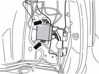
Applies to cars with reversing warning systems
- Remove the parking assistance system (PAS) behind the right-hand rear wheel arch in order to access the accessory electronic module (AEM). If necessary, also disconnect the wiring around this.
Applies to the S40 and V50
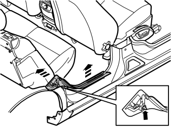
- Pull the top edge of the sill trim panel in the right-hand rear door inwards until the clips on the inside release. Then continue down and pull the panel upwards until the remaining two clips on the underside release.
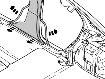
- Pull off the rubber mouldings at the rear edge of the right-hand front door and at the front edge of the right-hand rear door. This releases the lower panel on the B-post.
- Pull the bottom edge of the lower panel on the B-post until the two bottom clips release.
Connecting to the accessory electronic module (AEM)
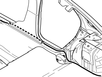
- Route the cable for the accessory electronic module (AEM), and the cable harness with the two green connectors, from the control module to the space in the glove compartment.
- Route the wiring under the floor carpets, inside the lower panel on the B-post and the insulation panels, back to the accessory electronic module (AEM) inside the panel in the rear edge of the right-hand rear wheel arch. Route the wiring along the existing cable harnesses in the cargo compartment.
Примечание: Ensure that the cable is positioned so that there is no risk of it catching or rubbing.
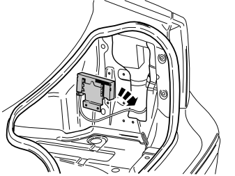
- Pull the accessory electronic module (AEM) away from its bracket in the rear edge of the right-hand rear wheel arch.
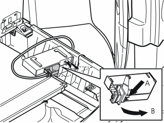
- Disconnect the large connector on the accessory electronic module (AEM). Press in the catch (A). Pull the black handle (B) in the direction of the arrows until a click is heard.
- Disconnect the connector from the accessory electronic module.
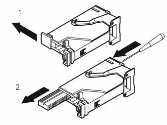
- Remove the black catch holding the black switch in place in the connector by pulling in the direction of the arrow.
- Remove the black switch by inserting a pointed object in the hole on the other shorter side. Press the switch out.
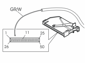
- Connect the green/white (GN/W) cable from the routed cable harness to terminal 11 in the black connector for the accessory electronic module (AEM).
Примечание: The numerical markings on the top and bottom of the black terminal pin are extremely small, so be careful when installing the cable.
- Reinstall the black switch in the connector. Lock into place using the catch.
- Press the connector into the Accessory Electronic module. Secure using the black locking handle.
- Reinstall the accessory electronic module (AEM) in its bracket.
Supplementary work
Cargo compartment
- Reinstall the insulation panel on the right-hand side (applies to V50).
- Reinstall the floor support (applies to V50).
- Reinstall the parking assistance system (PAS) control module if removed.
- Reinstall the side panel.
- Tighten the screws in the load securing eyelets. Tighten to 24 Nm (18 lbf.ft.) (applies to the V50).
- Reinstall the tailgate sill trim panel.
- Reinstall the upper floor support if applicable (applies to the S40)
- Reinstall the rubber strips in the boot lid opening
- Reinstall the cargo compartment carpet.
Passenger compartment
- Reinstall the B and C-post panels on the right-hand side.
- Fold the floor carpet back at the right-hand front seat.
- Reinstall the passenger compartment connector socket if fitted.
- Reinstall the sill trim panels on the right-hand side.
- Reinstall the rubber strips in the door openings on the right-hand side.
- Reinstall the side cushion.
- Position the backrest and seat cushions back into place.
Dashboard
- Reinstall the inner section of the glove compartment.
- Reinstall the lower vent.
- Connect the connectors for the lighting to the front section of the glove compartment. Tighten the glove compartment.
- Plug in the connectors and reinstall the soundproofing panel.
- Reinstall the clips in the vents on the ends of the dashboard.
- Reinstall the panels on the ends of the dashboard.
- Connect and reinstall the media player.
- Reinstall the centre console and connect the dashboard environment panel.
- Connect and reinstall the display unit.
- Press the surround for the display into place.
- Reinstall the panel inside the centre console.
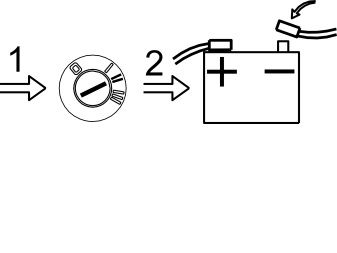
- Reconnect the battery negative lead.
- Programme the software in accordance with the service information in VIDA.
Обсуждение и оценка
0Пока нет комментариев. Будьте первым.