Примечание: Before beginning work, check the fuel level using the fuel gauge in the combined instrument panel.
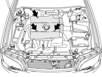
- Remove the engine splash guard secured by three screws.
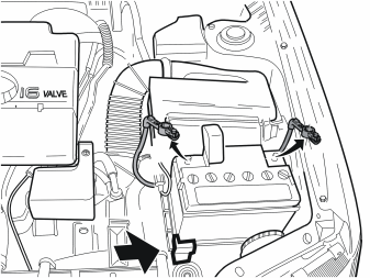
- Note the anti-theft radio code (if applicable)
- Turn the ignition key to position 0
- Disconnect the battery positive and negative leads
- Remove the battery clamp
- Remove the battery.
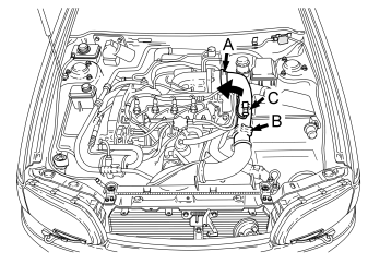
- Disconnect the hose clamp (A) from the intake manifold on the engine. Pull off the hose
- Remove the clamp (B) on the intake manifold. Twist the pipe away from the hoses underneath
- If necessary remove the existing connector (C).
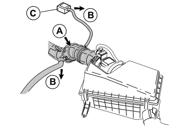
- Remove the intake hose (A) between the turbocharger (TC) and the air cleaner
- Remove the connected vacuum hoses (B) from the clamps and valve (C) to access the intake hose
- Remove the air cleaner (ACL).
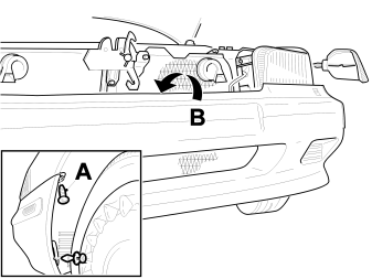
- Remove the indicator lamps on the right and left-hand sides
- Remove the screw (A). Remove the mounting screws or clips for the splash guards on the left and right-hand sides
- Remove the cable clip (B) for the cable harness from the front bumper.
Where applicable:
- Disconnect the connectors from the outside temperature sensor and the headlamp wipers
- Disconnect the washer hose for the headlamp wipers from the T-piece.
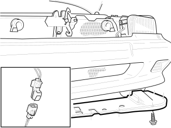
- Remove the front splash guard under the engine. Disconnect the connectors for the sidemarker lamps.
Where applicable:
- Disconnect the connectors for the front fog lamps.
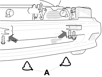
- Remove the plugs (A) from the front bumper
- Remove the four mounting screws for the bumper
- Where applicable: Fold the wiper arms for the headlamps forwards
- Remove the front bumper assembly.
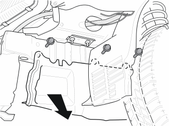
- Remove the three screws
- Remove the cover (it will not be used again).
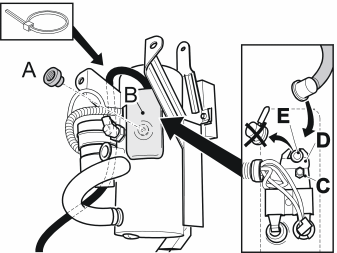
- Remove the nut (A), cover (B), nut (C), bracket (D) and seal plug (E)
- Apply petroleum jelly to the O-ring for the fuel driven heater. Install the fuel line with the bracket (D) and nut (C). Tighten to 4 Nm
- Install the cover (B) and nut (A)
- Secure the fuel line. Use a tie strap.
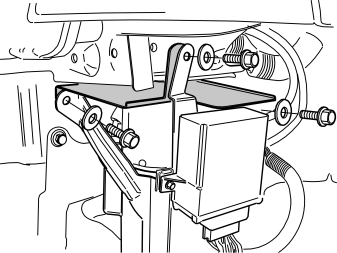
- Install the fuel driven heater together with the protective plate, using the three screws as illustrated. The protective plate must be positioned in the two front screws for the heater and the mounting brackets must be positioned nearest the body.
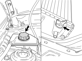
- Unscrew the expansion tank cap
- Open the drain nipple on the radiator. Collect the coolant in a container
- Close the drain nipple.
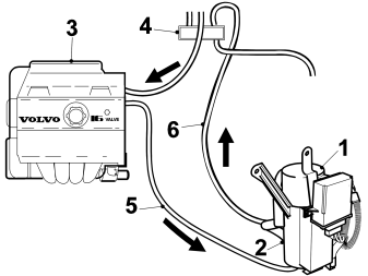
Connecting the hoses:
- Fuel driven heater
- Water pump
- Engine
- Connection
- Between the engine and water pump
- Between the upper connection on the fuel driven heater and the cowl connection.
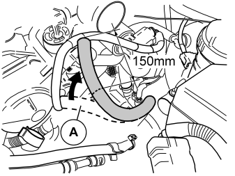
- Remove the outlet hose (A) on the cylinder head. Between the cylinder head and the connection in front of the cowl
- Cut off the hose 150 mm from the engine. The excess hose piece will not be reused.
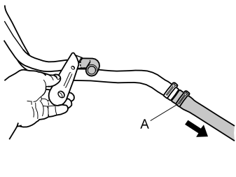
- Take the hose unit from the kit and cut off the hose bend as illustrated
- Remove the clamp (A). Pull off the joining hose from the hose unit. The hose will be reused.
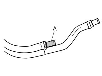
- Install the butt connector (A) and clamp from the kit, on the cut hose in the hose unit
- Tighten the clamp.
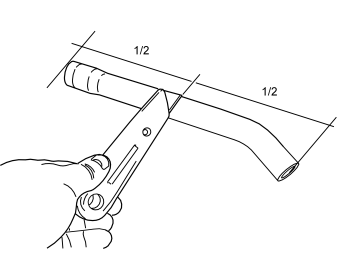
- Cut the hose previously removed from the hose unit, in the centre. The straight section will be reused.
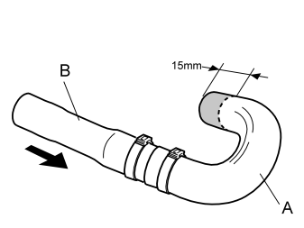
- Take one butt connector, hose bend (A) and two clamps from the kit. Press the butt connector into the white marked end on the bent hose
- Take the previously cut straight hose section (B). Press this onto the butt connector
- Install and tighten the clamps
- Cut 15 mm off the other end of the bent hose.
Illustration A
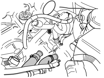
- Take the prepared large hose unit and position in the engine compartment on top of and at the side of the lower charge air pipe, on the right-hand side of the fuse box. The hose unit must also be positioned under the miscellaneous smaller hoses.
Примечание: The hose unit must not be positioned in the large plastic clamp holding both the charge air pipes to each other.
Illustration B
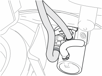
- Position the hose unit in the outlet in the battery shelf. Route the hose to the terminals on the parking heater water pump
- Connect the hoses to the outlet on the water pump.
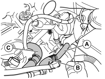
- Position a hose clamp (from the kit) on the cut hose (A) that ran to the cylinder head
- Connect the butt connector on the hose (B) in the installed hose unit to the cut hose (A)
- Tighten the hose clamp
- Install the two hose clamps (from the kit) on the bent hose (C) prepared earlier, one at each end
- Connect the longer straight section of the bent hose to the butt connector on the shorter hose in the hose unit and the other end to the cylinder head
- Position the hose clamps and tighten
- Secure the hose using a tie strap in the lowest turbo pipe away from the gear selector.
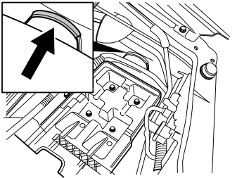
- Take the guard from the kit. Press the guard on the plate edge in the body, on the left-hand side of the battery holder.
Illustration A
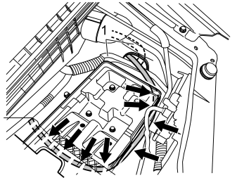
- Route the fuel line in the rear section of the hole in the body above the heater, at the rear edge of the cable lead-in (1)
- Route forward over the existing cable harness along the front edge of the battery holder. Then route backwards under the right-hand end of the battery holder, back to the junction box at the front member under the fusebox
- Route the fuel line further along the junction box and clamp using two tie straps from the kit.
Illustration B
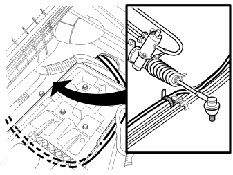
- Route the fuel line to the rear section of the engine compartment. Route to the fuel lines secured at the cowl. Clamp the line using a tie strap from the kit.
Осторожно: Ensure that the fuel line is not bent at odd angles or damaged in such a way that holes may be caused.
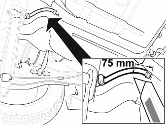
- Slacken off the fuel tank filler cap to release the overpressure in the fuel tank. Then tighten the fuel tank filler cap again.
Осторожно: Check that the fuel level is below the level at which the fuel return hose will be cut.
- Cut the return hose as illustrated.
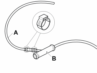
- Connect and tighten the suction hose (A) to the suction pipe (B).
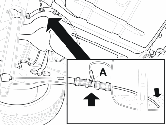
- Install the suction pipe in the fuel tank. Ensure that the end of the suction pipe is positioned as low as possible. (The connection nipple (A) points to the left)
- Clamp using tie straps from the kit.
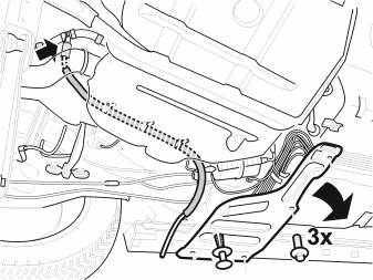
- Remove the splash guard at the left-hand front corner of the fuel tank
- Thread the protective sleeve over the suction hose
- Route the suction hose as illustrated. Secure the suction hose using a tie strap.
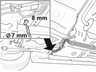
- Position the clip in the opening. Slide the clip as far in the opening as possible
- Mark the position for holes
- Remove the clip
- Drill a 7 mm diameter hole. Treat the edges of the holes using a rust-proofing agent.
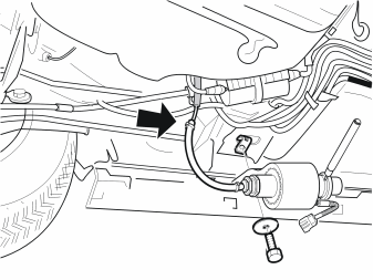
- Thread the rubber mounting over the fuel pump (FP)
- Position the fuel pump (FP). Tighten
- Cut the suction hose to the correct length
- Route the suction hose between the body side and the handbrake cable
- Connect the suction hose.
Примечание: Ensure that the fuel pump (FP) is not in direct contact with the chassis.
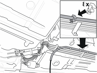
- Install the retaining clip for the fuel line
- Route the fuel line along the existing line towards the rear of the car
- Press the fuel line into the clips.
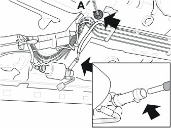
- Cut the fuel line to the correct length
- Connect the fuel hose. Secure the fuel hose using a tie strap
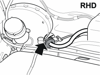
- Open tie strap and remove the rubber grommet (A) from the floor.
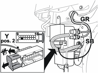
- Route any extra cable harness from the engine compartment to the fuel driven heater
- Route down to the front edge of the oval hole to where fuel line was routed
- Apply grease to the connectors
- Connect the grey (GR) and black (SB) connector
- Open and disconnect the 16-pin connector
- Remove the blind cover plug. Connect the yellow (Y) cable to terminal 2 in the connector
- Reconnect and lock the 16-pin connector
- Secure the cable harnesses using tie straps.
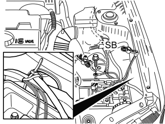
- Route the cable harness through the engine compartment as illustrated
- Connect the black (SB) cable to ground as illustrated. Tighten to 20 Nm
- Secure the cable harness and fuel line at the existing cable harness using tie straps from the kit. Ensure that the fuel line and cable harness are not close to the plate edge.
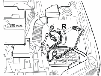
- Connect the red (R) cable to the battery positive lead as illustrated
- Carefully secure the fusebox and cable harness to the existing cable harness using tie straps.
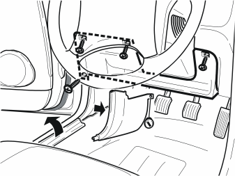
- Remove the sill trim panel
- Remove the panel under the dashboard. Remove the A-post panel on the driver's side
- Disconnect the courtesy lighting cables.
For right-hand drive cars reverse the working method.
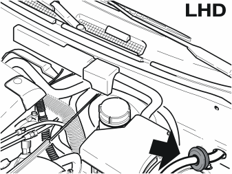
- Remove the rubber grommet for the accessory grommet
- Route the cable harness through the accessory lead-in
- Install the rubber grommet. Ensure that the rubber grommet is sealed.
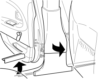
- Remove the rear door sill trim panel and B-post panel on the driver's side.
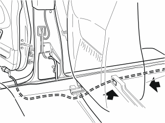
- Route the cable harness for the fuel pump (FP) along the existing cable harness via the channel under the driver's seat to the back seat
- Secure the cable harnesses using tie straps.
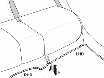
- Carefully pull up the floor carpet
- Route the cable harness through the existing hole The connector must be removed to insert the cable harness.
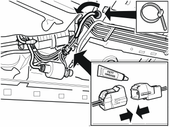
- Route the cable harness through the hole
- Apply grease to the connector
- Connect the connector and secure using a tie strap
- Reinstall the rubber grommet. Secure using a tie strap
- Check that the fuel pump (FP) is free of the chassis and existing pipes
- Reinstall the splash guard at the fuel tank.
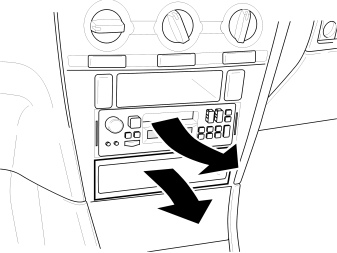
Where applicable:
- Remove the radio
- Remove the storage compartment from the centre console.
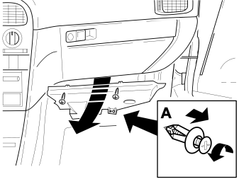
- Remove the screws and clips (A)
- Remove the panel under the dashboard on the driver's side.
Circle those points that apply for each variant D, E or F. D = From chassis number 361 762 to 600 000:Cars with manual climate control (MCC): points 42, 45-54 and 58-70.E = From chassis number 361 762 to 600 000; Cars with electronic climate control (ECC): points 43, 45-48, 55-56, 58-62 and 65-70. F = From chassis number 600 000 inclusive; All cars: points 44-48, 55, 57-62, 65-70.
Applies to version D
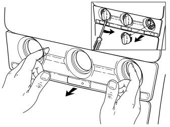
- Remove the heater controls
- Remove the front panel. (Some force is required).
Applies to variant E
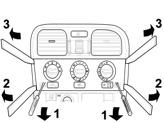
- Press the hooks behind the panel upwards by inserting your fingers in the control holes on the electronic climate control panel
- At the same time pull the lower edge of the panel towards you. (Use the special tool (P/N 9814071))
- Press the entire panel upwards slightly. Carefully pull the top edge of the panel towards you (the panel is tightly secured). (The controls remain on the heater control panel).
Applies to version F
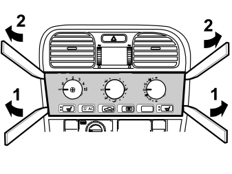
- Carefully insert special tool (P/N 9814071) between the dashboard and the lower edge of the short side of the heater panel. Pull the lower edge of the panel towards you
- Press the entire panel upwards slightly. Carefully pull the top edge of the panel towards you (the panel is tightly secured). Remove the panel.
Applies to variants D/E/F
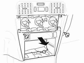
- Remove the three screws
- Where applicable: Disconnect the connectors
- Remove the dashboard.
Applies to variants D/E/F
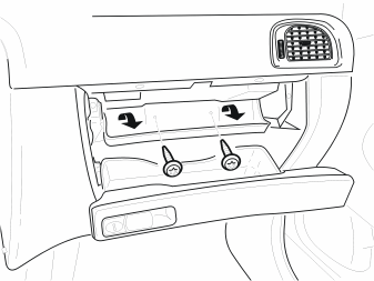
- Open the glove compartment
- Remove the two screws. Unhook the compartment.
Applies to variants D/E/F
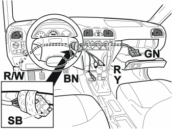
- Route the cable harness behind the dashboard as illustrated.
For right-hand drive cars reverse the working method.
If the timer is a type 4 model:
- Tape the black (SB) 4-pin connector to the cable harness. (It will not be used).
If there is a mini-timer:
- Tape the green (GN) 10-pin connector to the cable harness. (It will not be used).
Applies to variants D/E/F
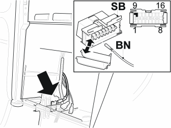
- Disconnect the black (SB) data link connector (DLC) from the bracket in the dashboard
- Open the connector. Connect the brown (BN) cable to terminal 9 in the connector
- Close the connector. Reconnect the connector.
Applies to version D
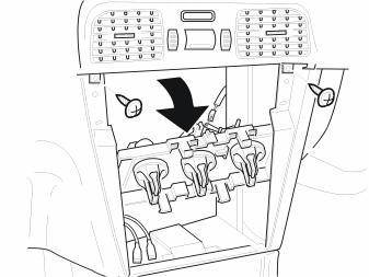
- Remove the two screws. Angle the control unit downwards.
Applies to version D
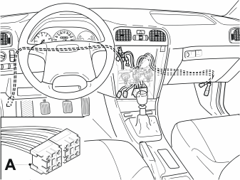
- Use the cable harness for the heater with two relay bases (A)
- Route the cable harness for the heater behind the dashboard as illustrated.
Applies to version D
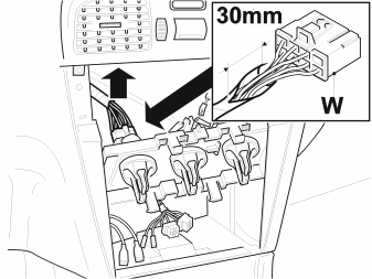
- Disconnect the white (W) connector
- Remove 30 mm of the masking tape.
Applies to version D
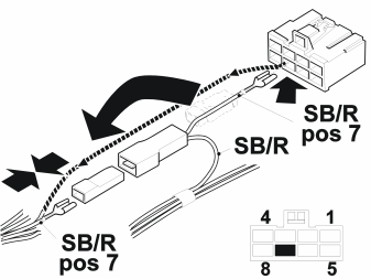
- Release the black/red (SB/R) cable from terminal 7. Install a connecting socket
- Connect the black/red (SB/R) cable to the black/red (SB/R) cable from the cable harness for the heater
- Connect the black/red (SB/R) cable from the cable harness for the heater to terminal 7 in the connector.
Applies to version D
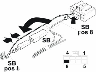
- Disconnect the black (SB) cable with a 3 mm2 area from terminal 8. Install a connecting socket
- Connect the black (SB) cable to the black (SB) cable from the cable harness for the heater
- Connect the black (SB) cable from the cable harness for the heater to terminal 8 in the connector
- Reconnect the connector to the heater control unit.
Applies to version D
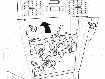
- Reinstall the heater control unit.
Примечание: Check that the control unit mechanism functions correctly.
- Continue with point en-GB0900c8af81e3de6d#KC08715885.
Applies to variants E/F
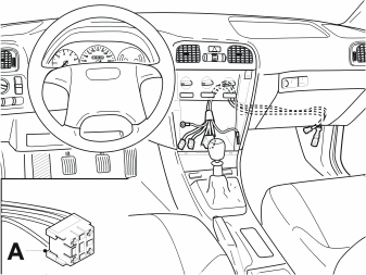
- Use the cable harness for the heater with one relay base (A)
- Route the cable harness for the heater behind the dashboard as illustrated.
Applies to variant E
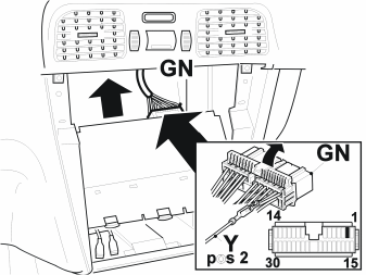
- Remove the two screws. Angle the control unit downwards
- Disconnect the green (GN) connector
- Open the connector. Connect the yellow (Y) cable to terminal 2 in the connector
- Close the connector. Reconnect the connector
- Reinstall the heater control unit.
Applies to version F
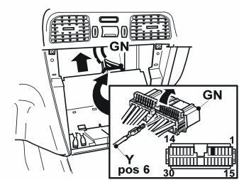
- Remove the two screws. Angle the control unit downwards
- Disconnect the green (GN) 30-pin connector
- Open the connector. Connect the yellow (Y) cable to terminal 6 in the connector
- Close the connector. Reconnect the connector
- Reinstall the heater control unit using the two screws.
Applies to variants D/E/F
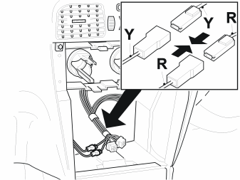
- Connect the yellow (Y) cable from the cable harness for the heater to the yellow (Y) cable
- Connect the red (R) cable from the cable harness for the heater to the red (R) cable.
Applies to variants D/E/F
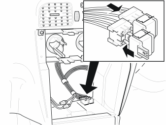
- Applies to version D: Slide the relay bases together
- Install the relay using relay clips
- Install the relay in the centre console.
Applies to variants D/E/F
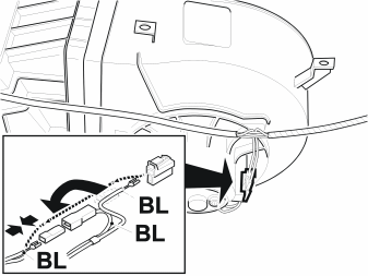
- Disconnect the 2-pin connector from the motor for the blower fan. (Look behind the dashboard on the passenger side)
- Connect the blue (BL) cable to the blue (BL) cable from the cable harness for the heater
- Connect the blue (BL) cable from the cable harness for the heater to the connector
- Reconnect the connector.
Applies to variants D/E from chassis number 361762 and variant F
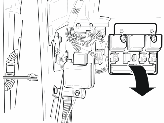
- Remove two nuts from the relay box
- Turn the relay box so that the reverse is accessible.
Applies to variants D/E from chassis number 361762 and variant F
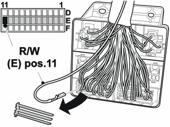
- Remove the lock
- Connect the red/white (R/W) cable to terminal 11 in the terminal block (E)
- Reinstall the lock
- Reinstall the relay box.
Applies to version D
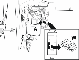
- Remove the nut (A)
- Turn the fusebox so that the lower white (W) 22-pin connector on the reverse can be disconnected.
For right-hand drive cars reverse the working method.
Applies to version D
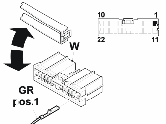
- Open the connector
- Connect the grey (GR) cable to the terminal 1 (this is a +15/2 terminal)
- Close the connector. Reconnect the connector.
If there is a mini-timer:
- First see the separate instructions and then continue to point 67.
If the timer is a type 4 model:
- Carry out the work method below point 65 and 66
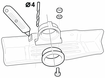
- Install the spacer ring in the bracket for the timer
- Install the bracket for the timer in the storage compartment
- Mark the position for making holes. Drill two 4 mm diameter holes
- Install and tighten the bracket for the timer
- Cut out an opening for the cable harness for the timer in the storage compartment.
Applies to variants D/E/F
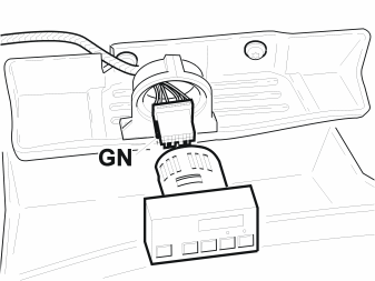
- Reinstall the centre console locker in the glove compartment
- Connect the green (GN) connector
- Press the timer into the bracket.
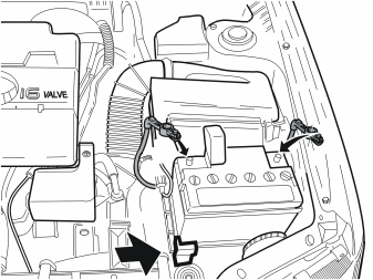
Reinstall:
- the air cleaner (ACL)
- the intake hose between the turbocharger (TC) and the air cleaner (ACL)
- the vacuum hoses removed from the clamp and valve
- the upper intake pipe for the charge air cooler. Connect the removed connector
- the battery and secure to the battery clamp.
Внимание: Ensure that nobody is in the car when the battery is being reconnected.
- Turn the ignition key to position II
- Reconnect the battery negative and positive terminals. Check that the fuses are secured correctly
- Enter the anti-theft radio code
- Set the car clock and the timer to the correct time.
Осторожно: Ensure that the radiator hoses and wiring are not rubbing.
Applies to variants D/E/F
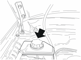
- Fill the cooling system with the coolant that was drained
- Run the engine until the thermostat opens and top up if necessary
- Check that there is no leakage.
Applies to variants D/E/F
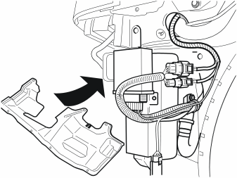
- Install the new splash guard from the kit using 3 screws
- Activate the fuel driven heater. Check the function. (See the instruction manual).
Примечание: It may be necessary to start the heater repeatedly due to air in the fuel line.
- Check for any fuel and coolant leakage. Check the coolant level and top-up if necessary.
Applies to variants D/E/F
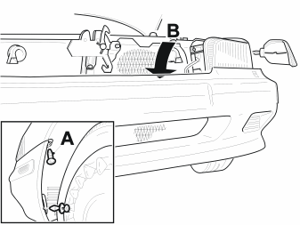
- Reinstall the front bumper
- Install the mounting screws or clips for the splash guards on the left and right-hand sides
- Connect the connectors. Connect the indicator lamps.
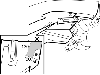
- Mark for making holes for the exhaust outlet for the fuel driven heater in the front splash guard under the engine
- Saw out the hole. (Use a compass saw)
- Reinstall and secure the front splash guard under the engine
- Reinstall the remaining components.
Обсуждение и оценка
0Пока нет комментариев. Будьте первым.