Применимость
| Модель | Двигатель | Год |
|---|---|---|
| XC90 | B5254T2 | 2004–2007 |
Примечание: This accessory requires software unique to the car.
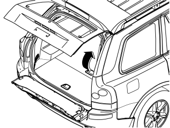
Applies to cars with two rows of seats
- Remove the front floor hatch by first lifting it up a bit and then pulling it out of the mountings in the front edge.
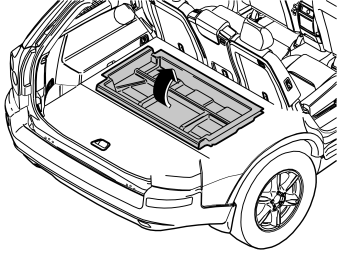
Applies to cars with two rows of seats
- Lift out the front storage box.
Примечание: Removal of the right seat in the second row (steps 3-8) applies to all cars. For cars with three rows of seats, the left seat and centre seat of the second row must also be removed. See step 9.
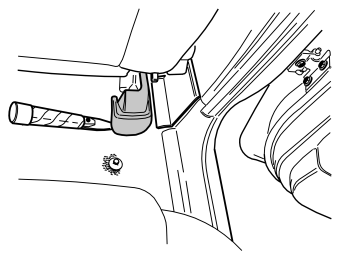
- Remove the panel on the right rear mounting on the right-hand front seat. Prise up the rear edge of the panel slightly and then pull rearwards and upwards.
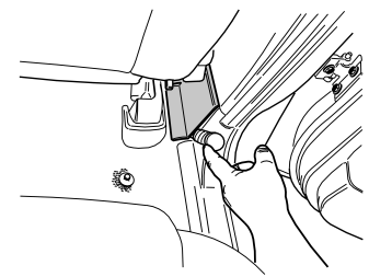
- Slide the seats of the first row as far forward as possible.
- Carefully prise loose and remove the panel over the joint between the door sills on the right side.
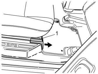
- Remove the panel for the right front seat mounting of the second row's right-hand seat by pressing down the catch (1) on top and pulling the panel forward. Remove the screw underneath.
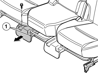
- Remove the panel for the front seat mountings of the second row's right-hand seat/centre seat by pressing down the catches (1) on top and pulling the panel forward. Remove the screw for the right-hand seat.
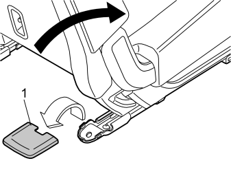
- Lower the backrest of the right-hand seat in the second row.
- Remove the cover (1) of the rear seat mountings of the right-hand seat by prising the rear edge loose. Remove the screws.
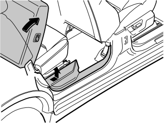
- Undo the sill panel of the right rear door. Pull the rear edge until the clips release. Continue forward until the remaining clips release.
- Unhook the sill trim panel from the B-post panel. Place the sill trim panel in the cargo compartment.
- Remove the seat.
Осторожно: Exercise care when lifting the seats out of the passenger compartment so the mountings do not damage the door panels.
Applies to cars with three rows of seats
- Remove the corresponding panels and screws on the left-hand side and for the left-hand and centre seat of the second row following steps 3-8.
- Remove the left-hand and centre seat.
Осторожно: Exercise care when lifting the seats out of the passenger compartment so the mountings do not damage the door panels.
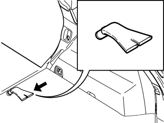
Applies to cars with three rows of seats
- Remove the air nozzles on the right and left-hand side.
Illustration A applies to cars with two rows of seats
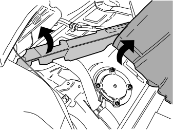
- Bend aside the floor mat and secure it with the seat belt on the left-hand side.
- Carefully bend aside the styrofoam insulation to provide access to the cover of the tank fixture.
Осторожно: Take care. The styrofoam insulation comes off easily.
Illustration B applies to cars with three rows of seats
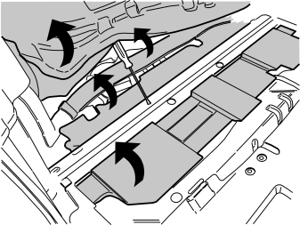
- Bend aside the floor mat and the insulating mat.
- Use a screwdriver or the like to hold the mat in place.
- Remove the air duct.
- Remove both panels of styrofoam insulation.
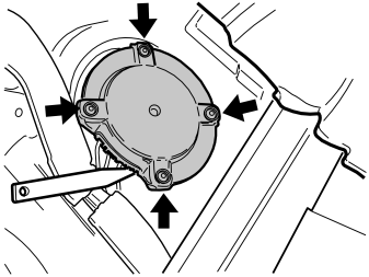
- Remove the four screws in the tank fitting cover.
- Carefully prise loose the cover using a weatherstrip tool.
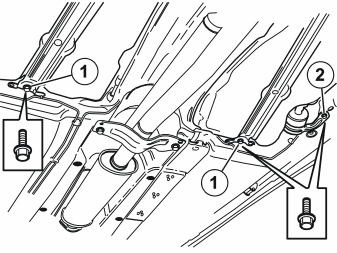
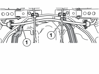
- Remove the four screws (1) from the front and rear mountings of the fuel tank so that the tank is lowered a bit in order to fit a suction line to the fuel tank. If necessary, loosen and unscrew the fuel filter screw (2) to lower the fuel tank even more.
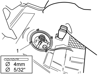
- Drill the connection (1) in the tank fitting with a Ø4 mm (5/32”) drill bit.
Примечание: Use a compressed air drill with a greased bit.
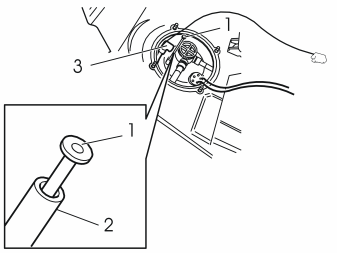
- Insert the pipe (1) from the kit down into the connection (2). Press the pipe down until it is flush with the connection.
- Take the fuel line with electrical line from the kit. Affix protective tape on the end of the fuel line that is to be inserted through the hole in the floor (the one with the short, unconnected line end).
- Insert the whole line assembly (3) between the floor and the fuel tank out to the right.
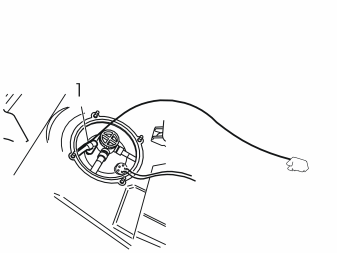
- Press the quick-release connector (1) onto the connection until a click is heard. Check that the quick-release connector is secure.
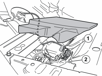
Applies to cars with two rows of seats
-
Carefully bend up the end of the styrofoam insulation.
-
Place a spacer underneath.
Applies to all models
- Route the line previously routed together with the fuel line under the seat frame and connect it to the front connector (1) in the contact bridge (2).
- Applies to cars with two rows of seats: Remove the spacer and fold down the styrofoam insulation.
- Place the line in the holder in the tank fitting cover.
- Refit the tank fitting cover and secure with the four screws.
- Refit the styrofoam insulation panels.
- Applies to cars with three rows of seats: Refit the air duct.
- Fold back the carpet.
- Applies to cars with three rows of seats: Refit the air nozzles under the outer seats.
- Reinstall the seats.
Осторожно: Exercise care when lifting the seats into the passenger compartment so the mountings do not damage the door panels.
- Secure the seats, tightening the screws to 48 Nm (35 lbf.ft.).
- Refit the panels and the covers over the seat mountings.
- Refit the panels over the joints between the door sills.
Applies to cars with two rows of seats
- Refit the front storage box.
- Refit the front floor hatch.
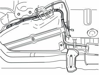
- Route the fuel hose with wiring harness (1) forward in the rear edge of the fuel tank. Route it along the fuel tank's right side and forward. Let it hang down.
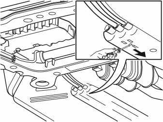
- Undo the rail for the fuel line by inserting a small screwdriver in the little hole between the rail and the yellow clip. Move the clip in the same direction as the oblong hole in the rail. The rear black clip has a little spot on the clip where you position the screwdriver and move it forward.
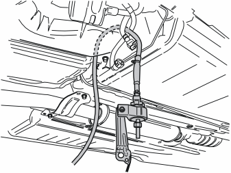
- Take the fuel pump with line from the kit. Insert the line in the front edge of the fuel tank's right side.
- Route the fuel line so that is next to the existing fuel line in the cut-out on top of the fuel tank. Then position the fuel line on the right-hand side of the wiring which runs to the engine compartment.
- Pull up the fuel line so that the fuel pump (FP) is positioned approximately as illustrated.
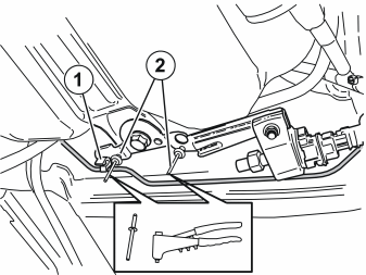
- Remove the brake pipe (1) from the clamp.
- Take the fuel pump with bracket and place the bracket on the top of the fuel tank mounting bracket in front of the small holes for the pop rivets.
- Use two metal pop rivets (2) from the kit to rivet the fuel pump bracket at the fuel tank mounting bracket.
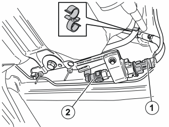
- Use a double clamp from the kit to clamp the two fuel lines from the fuel pump to each other at the two blue markings on the fuel lines.
- Press the brake pipe back into the clamp.
- Tighten the four screws that hold the tank in place. Tighten the screw of the fuel filter if this was loosened. Tighten the screws to 24 Nm (18 lbf.ft.).
- Connect the connector (1) from the pre-routed power cable to the fuel pump (FP).
- Connect the quick-release connector (2) on the pre-routed fuel line to the fuel pump (FP).
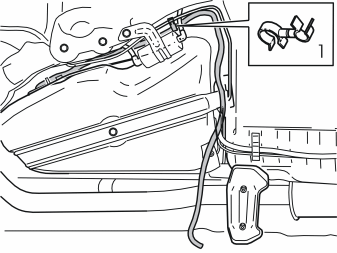
- Use a double clamp from the kit to clamp the fuel line at the fuel pipe at point (1).
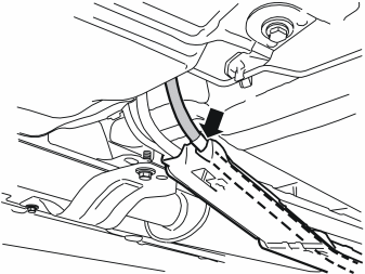
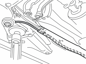
- Press the fuel hose from the recently installed fuel pump (FP) into place. Press into place in the bottom of the rail and forwards, in the cut-out furthest to the right.
Примечание: The marking on the fuel hose must be opposite the point where the fuel hose goes into the rail.
- Slide back the retaining clip for the rail. Press the rail against the car body. Ensure that the rail is securely installed.
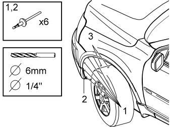
- Remove the left front wheel.
- Drill out the five pop rivets (1) holding the wing liner in place and the pop rivet (2) in the bottom edge of the bumper. Use a Ø6 mm (1/4”) drill bit.
Remove:
- any rivet residue
- the plastic nuts (3) holding the wing liner in place
- the small protective plate.
Applies to cars with the accessory side decor
-
Примечание: > Do not undo the side decor of the front wing.
Bend aside only the retaining lugs on the side decor of the front wing so that the edge of the wing liner can be released.
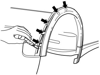
Applies to cars without the accessory side decor
- Undo the wing extension by carefully prising loose the lower corner using a weatherstrip tool.
- Pull it loose up to the highest point of the wheel housing until the three catches in the lower edge and the two clips a little higher up have released.
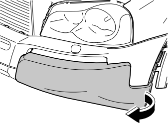
- Remove the left bumper panel by carefully prising it loose in the left bottom edge until the clips on the bottom and inside release. Continue pulling until the clips all around release.
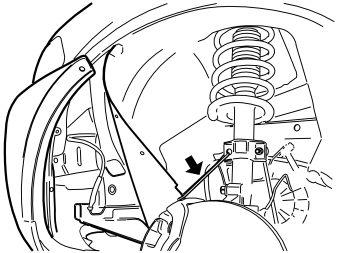
- Bend aside the wing liner and secure it with a tie strap or the like.
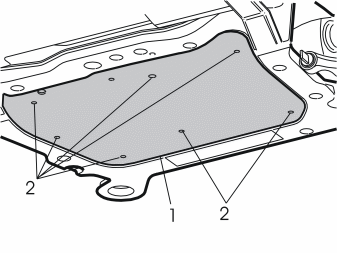
- Remove the protective engine plate (1) by removing the screws (2).
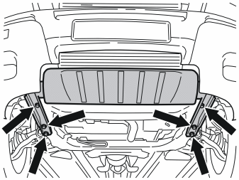
- Remove the front skid plate by first removing the six screws (1) on the bottom.
- With the aid of a helper, pull the skid plate forward. Pull one corner until one of the skid plate retaining lugs releases from the sub-frame. Then undo the other corner. At the same time, it may be necessary to carefully bend down the bottom edge of the bumper lining.
- Open the cap of the radiator expansion tank.
- Install a hose on the engine coolant drain nipple.
- Open the drain nipple. Drain off the coolant.
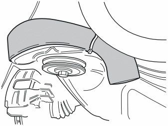
- Pull off and push the pipe elbow to one side so that the fuel pipe can be positioned.
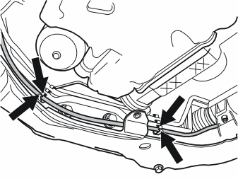
- Remove the power steering pipes and the plastic hose from their clips to make installing the fuel pipe easier. The rubber coated clamp on the upper side of the front edge of the sub-frame may need to be removed in order to push the upper power steering pipe to one side.
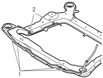
- Take the fuel pipe with the four pre-mounted clips (1) from the kit and fit it to the sub-frame. Insert it between the loosened pipes and the sub-frame. Press it into place with the clips in the sub-frames front edge and in the bottom on the clips (2) holding the plastic hose in place. The space is tight, so the fuel pipe must be bent and twisted to get it into place.
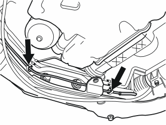
- Refit the power steering pipes and press the plastic hose into place on the outside of the fuel pipe. Refit the rubber-coated clamp if it was removed.
- Check that the fuel pipe does not catch on the sub-frame. Ensure that the fuel pipe does not rub against pipes or screw heads for the suspension.
- Reinstall the pipe elbow.
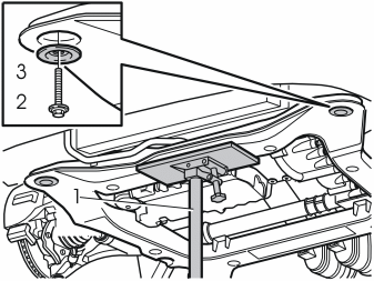
- Position the workshop lift (1) under the front edge of the sub-frame.
- Take the weight off the sub-frame.
- Remove the screw (2) and washer (3) from the left front mounting on the sub-frame.
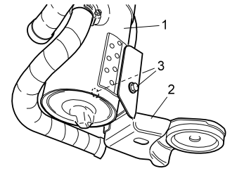
- Fit the heater (1) on the bracket (2) with the screws (3) from the kit and tighten.
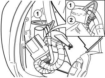
- Raise the heater into its installation position.
- Take a small hose clamp for the fuel line from the kit. Install the clamp on the fuel hose (1) from the fuel pipe on the sub-frame.
- Press the fuel line on the inlet (2) on the fuel pump (FP). Tighten.
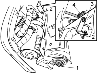
- Take a new screw (1) from the kit and secure the heater to the left front corner of the sub-frame. Do not tighten hard yet.
- Take the metal bracket and two nuts from the kit.
- Position one of the metal bracket's retaining lugs on the stud (2) of the heater and fit the nut. Tighten loosely.
- Position the other retaining lug of the bracket on the stud (3) and fit the nut.
- Tighten the heater to the sub-frame and bracket. Tighten the screw (1) to 105 Nm (78 lbf.ft.). Angle tighten to 120° or max. 280 Nm (206 lbf.ft.)
- Remove the protective cap from the pre-routed connector (4). Press in the catch on the top and pull it off.
- Connect the cable from the heater to the connector.
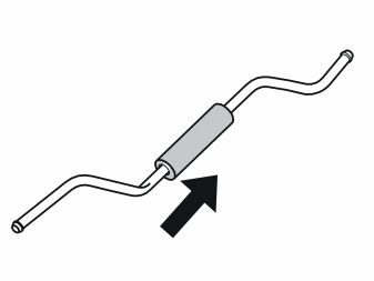
- Take the chafing protection and short fuel pipe from the kit. Fit the chafing protection on the pipe.
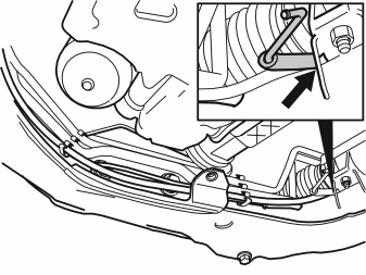
- Insert the end of the short fuel pipe, which is bent in two places, under the power steering servo and the anti-roll bar, on top of the right rear corner on the sub-frame.
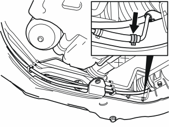
- Take a hose clamp from the kit. Thread the hose clamp onto the short fuel line on the fuel pipe on the sub-frame.
- Connect the short fuel pipe to the fuel line. Slide the pipe into the fuel line. Slide the pipe in so that the two pipes are in contact with each other. This prevents air pockets from forming.
- Squeeze the hose clamp together.
Illustration A
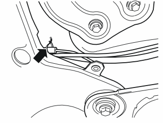
- Take a tie strap from the kit. Clamp the protective tube at the fuel pipe so that it is securely installed.
Illustration B
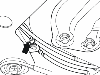
- Take a hose clamp from the kit. Thread it on the fuel line to the fuel pump that was routed previously. Connect the fuel line to the short fuel pipe. Slide the pipe in so that the two pipes are in contact with each other. This prevents air pockets from forming.
- Ensure that the fuel line is routed correctly. Ensure that the fuel line does not obstruct the plastic hose or rub against the sub-frame or other components.
- Squeeze the hose clamp together.
Примечание: Fuel lines and fuel pipes must be at least 15 mm (19/32”) from brake pipes.
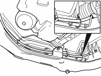
- Take a tie strap from the kit. Clamp the fuel pipe at the plastic hose.
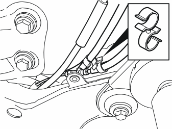
- Take a double clamp from the kit and clamp the fuel line of the parking heater at the ordinary fuel line.
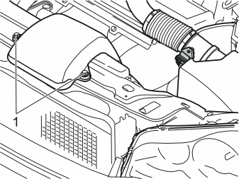
- Remove the two screws (1) from the induction pipe of the air filter.
- Remove the induction pipe and put it aside.
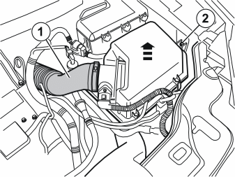
- Undo the hose clamp and detach the hose (1) from the air filter.
Примечание: If the hose is plastic, the hose joint will need to be carefully heated to release the hose. Use a hot-air gun.
- Pull the air filter from its mounting in the left front member and left wing liner.
- Unscrew the plastic nut (2) in the wing liner. It will be re-used.
- Move aside the air filter from the gearbox by tying it up with a string or the like. Depending on its design, several hoses or connectors may need to be disconnected around the air filter.
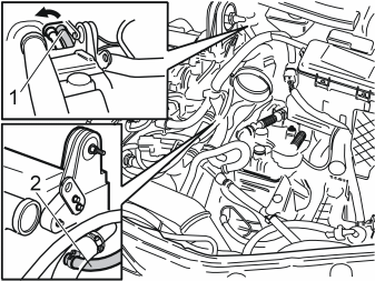
- Undo the quick-release connector on the cabin heater's left heater hose (1): Hold in the circlip of the quick-release connector in front of the two arrow tips while turning the circlip in the direction of the arrow. Turn the quick-release connector slightly and pull it out.
- Detach the heater hose (2) on the left side of the cylinder head.
- Detach the thick coolant hose at the cylinder head to make it easier to fit the new radiator hose.
- Remove the heater hose. It will not be used again.
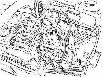
- Take the heater hoses from the kit. Thread them in the front edge of the gearbox and out to the left front mounting of the sub-frame.
- Connect the short heater hose to the connection (1) on the left side of the cylinder head. Secure it using a new hose clamp from the kit.
- Route the long heater hose along the inside of the left front member over the gearbox, behind the induction pipe to the turbocharger and along the same route as the old heater hose. Connect it where the old heater hose was detached.
- Reattach the thick coolant hose at the cylinder head if this was detached.
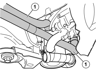
- Connect the two heater hoses (1) to the heater using hose clamps from the kit and tighten.
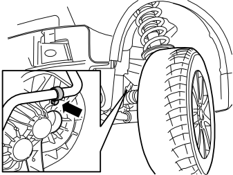
- Take the rubber-coated clamp and M8x16 screw from the kit. Clamp the heater hose from the bulkhead, tightening the clamp at the existing hole in the gearbox end above the drive shaft.
- Tighten the drain nipple on the radiator. Remove the hose.
- Refit the protective engine plate and tighten to 25 Nm (18 lbf.ft.)
- Refit the front skid plate and tighten to 50 Nm (37 lbf.ft.)
- Bend back the wing liner. Refit and tighten the small plate and nuts.
- Press the wing extension into place.
- Use the pop rivets from the kit to rivet the front/lower edge of the wing liner into place.
- Refit the bumper panel.
- Remount the wheel and tighten the bolts to 140 Nm (103 lbf.ft.)
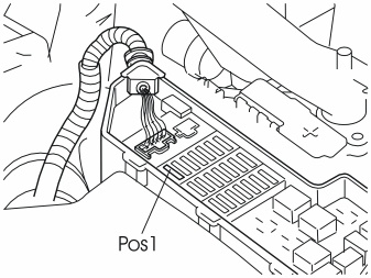
- Remove the cover from the fuse box in the engine compartment. Install a 25A fuse in position 1.
- Reinstall the cover.
- Fill with coolant. Reinstall the expansion tank cap.
- Refit the air filter and reconnect any disconnected cables or hoses.
- Refit the induction pipe on the front plate between the headlamps. Tighten the screws to 10 Nm (7 lbf.ft.)
- Start the engine and bleed the cooling system.
- Program the software according to the service information in VIDA.
- Test the heater function according to separate instructions.
Обсуждение и оценка
0Пока нет комментариев. Будьте первым.