Применимость
| Модель | Двигатель | Год |
|---|---|---|
| S60 (-09) | B5254T4 | 2004–2007 |
| S60 (-09) | — | 2004–2009 |
| V70 (00-08) | B5254T4 | 2004–2007 |
| V70 (00-08) | — | 2004–2008 |
Interior preparations, applies to the V70
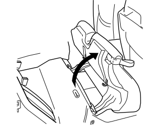
- Fold the right-hand rear seat cushion forward.
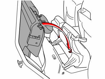
- Fold the right-hand rear backrest forward.
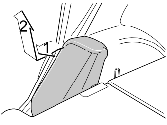
- Remove the right-hand side cushion. First pull the top edge (1) towards you. Then lift the side cushion upwards (2).
Interior preparations, applies to the S60
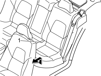
- Remove the rear seat cushion (1) by pulling it up at the front and then forwards.
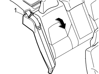
- Fold the right-hand rear backrest forward
- Remove the seat belt from the guide (1).
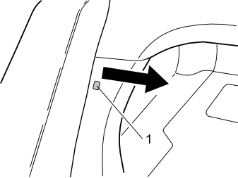
- Remove the clip (1) at the side of the right-hand side cushion
- Pull out the top edge of the left front panel in the cargo compartment to access the upper catch for the side cushion.
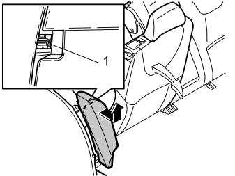
- Remove the right-hand side cushion. First press in the catches (1) at the top edge of the reverse of the side cushion. Pull the cushion out slightly
- Grasp the cushion using both hands. Twist the cushion clockwise until the catches on the inside release
- Remove the side cushion. First pull out the top of the side cushion. Then pull upwards.
Interior preparations, all models
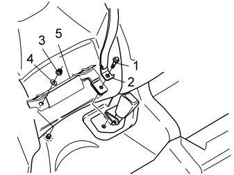
Applies to cars with mountings for Isofix on the right side of the rear seat
- Remove the screws (1). Slacken off the end mounting (2) for the seat belt
- Remove the nut (3) and the washer (4) from the stud
- Remove the mounting (5).
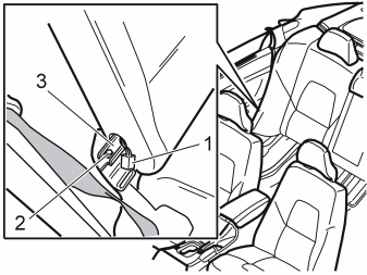
- Disconnect the connector (1) and the screw (2) on the right backrest
- Lift the mounting (3). Gently work the backrest backwards and forwards to release the pin from the mounting in the left backrest
- Remove the right backrest.
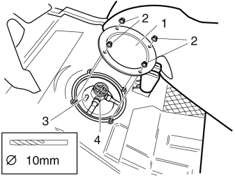
- Push the insulation panel to one side so that the cover (1) is accessible
- Remove the nuts (2) and the cover
- Drill out the connection (3) in the fuel tank unit (4). Use a 4 mm (5/32”) diameter drill bit.
Примечание: Use a compressed air power drill with a greased bit.
Illustration A displays the front mounting
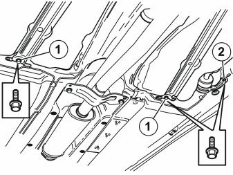
Illustration B displays the rear mounting
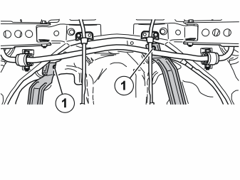
- Remove the four screws (1) in the front and rear mountings so that the fuel tank lowers slightly. This allows the suction pipe for the fuel tank to be installed
- If necessary, remove the screw (2) for the fuel filter to lower the fuel tank further.
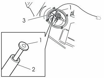
- Insert the pipe (1) (from the kit) into the connection (2). Press the pipe down until it is in contact with the connection
- Take the fuel line and electrical cable from the kit. Apply masking tape to the end of the part of the fuel line to be inserted down through the hole in the floor. (The one with a short free end.)
- Insert the whole pipe assembly (3) between the floor and the fuel tank out to the right.
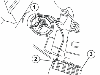
- Press the quick-release connector (1) onto the connection until a click is heard. Check that the quick-release connector is secure
- Connect the power cable, routed with the fuel line to the connector (2) in the connector bridge (3).
- Place the lines in the lead-in in the cover
- Reinstall the cover. Secure the cover using the four nuts.
Applies to cars with Isofix mountings
- Reinstall the Isofix mounting and seat belt buckle
- Tighten the screw. Tighten to 40 Nm (30 lbf.ft.).Tighten the nut. Tighten to 30 Nm (22 lbf.ft.).
Applies to all models
- Reinstall the backrests, side cushions and seat cushions
- Open the cover for the radiator expansion tank.
Exterior preparations
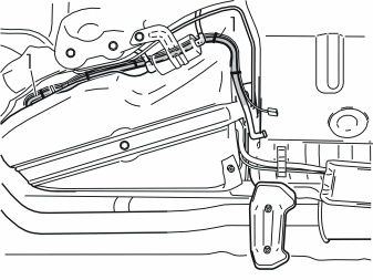
- Route the fuel hose and cable harness (1) at the rear edge of the fuel tank. Route it forwards along the right-hand side of the fuel tank. Leave it hanging down.
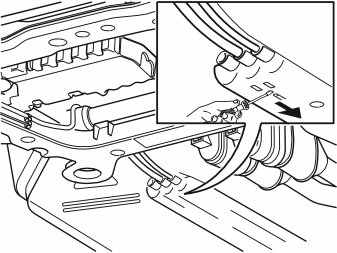
- Detach the fuel rail (1) at the front edge. First insert a small screwdriver into the small hole between the yellow clip and the fuel rail. Push the clip in the direction of the arrow. Repeat this for the other five clips
- Pull down the fuel rail so that it hangs from the hoses.
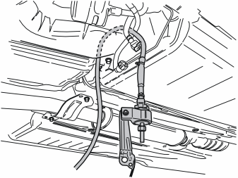
- Take the fuel pump (FP) and fuel line from the kit. Insert the fuel line up at the front edge on the right-hand side of the fuel tank
- Route the fuel line so that is next to the existing fuel line in the cut-out on top of the fuel tank. Then position the fuel line on the right-hand side of the wiring which runs to the engine compartment
- Pull up the fuel line so that the fuel pump (FP) is positioned as approximately as illustrated.
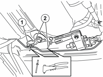
- Remove the brake pipe (1) from the clamp
- Take the fuel pump (FP) and bracket. Position the bracket on top of the bracket for the fuel tank mounting, opposite the small holes for the rivets
- Take two metal rivets (2) from the kit. Rivet the fuel pump (FP) bracket at the bracket for the fuel tank mounting.
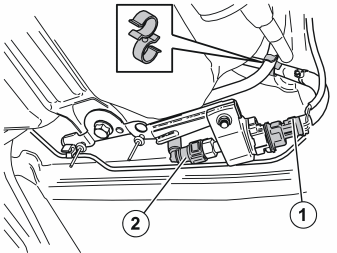
- Take the double clamp (1) from the kit. Secure the two fuel lines from the fuel pump (FP) to each other, opposite the two blue markings on the fuel lines
- Press the brake pipe back into the clamp
- Tighten the four screws holding the fuel tank. Also tighten the screw for the fuel filter if slackened off. Tighten the screws. Tighten to 24 Nm (18 lbf.ft)
- Connect the connector (1) from the pre-routed power cable to the fuel pump (FP)
- Connect the quick-release connector (2) on the pre-routed fuel line to the fuel pump (FP).
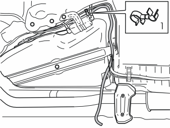
- Secure the fuel line in the brake pipe at point (1) using a double clamp from the kit.
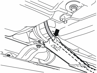
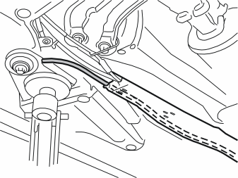
- Press into place the fuel hose from the recently installed fuel pump (FP). Press into place in the bottom of the rail and forwards, in the cut-out furthest to the right.
Примечание: The marking on the fuel hose must be opposite the point where the fuel hose goes into the rail.
- Slide back the retaining clip for the rail. Press the rail against the car body. Ensure that the rail is securely installed.
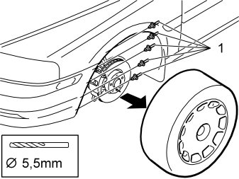
- Raise the car slightly
- Remove the left front wheel
- Raise the car a little more
- Drill out the five rivets (1) in the edge of the front left wheel housing. Use a 5.5 mm (7/32”) diameter drill bit.
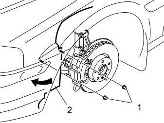
- Remove the two nuts (1) in the left wheel arch lining (2)
- Bend the wheel arch lining out of the way.
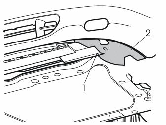
Applies only to models with an air baffle
- Remove the screw (1) from the left-hand air baffle (2) for the front brake
- Remove the left-hand air baffle by pulling it backwards (the air baffle will not be reused). Remove the right air baffle in the same way.
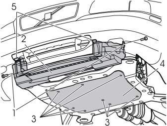
- Remove the air baffle (2). First remove the screws (1). Press up the catches (5). Pull the air baffle downwards and backwards
- Remove the splash guard (4) by slackening off the screws (3)
- Install a hose on the engine coolant drain nipple
- Open the drain nipple. Drain off the coolant.
Routing and installing hoses
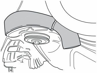
- Pull off and push the pipe elbow to one side so that the fuel pipe can be positioned.
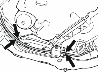
- Remove the power steering pipes and the plastic hose from their clips to make installing the fuel pipe easier. The rubber coated clamp on the upper side of the front edge of the sub-frame may need to be removed in order to push the upper power steering pipe to one side.
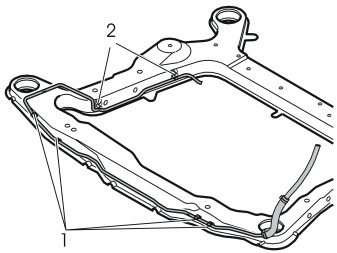
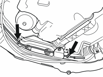
- Install the fuel pipe using the four pre-installed clips (1) (from the kit) on the sub-frame. Insert the fuel pipe between the disconnected pipes and the sub-frame. Press the fuel pipe into place. Use the clips in the front edge of the sub-frame and in the bottom in the clips (2) that secured the plastic hose. On older car models, there are two free clips for the fuel line below the existing pipes on the inside on the sub-frame. Due to the limited space, the fuel pipe needs to be worked slightly to position it correctly
- Reinstall the power steering pipes. Press the plastic hose into place on the outside of the fuel pipe. On older models, the plastic hose is reinstalled in its clips. Reinstall the rubber coated clamp if this has been removed
- Check that the fuel pipe does not catch on the sub-frame. Ensure that the fuel pipe does not rub against pipes or screw heads for the suspension.
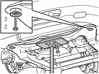
- Reinstall the pipe elbow
- Install the jack (1) under the front edge of the sub-frame
- Take the weight off the sub-frame
- Remove the screw (2) and the washer (3) from the front left mounting on the sub-frame.
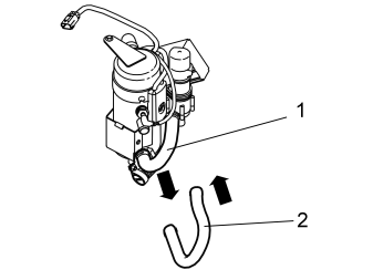
- Remove the hose clamps from the rubber hose (1)
- Pull the rubber hose from the fuel heater pipe
- Install the new hose (2). It must be positioned as illustrated
- Secure the new hose using the old clamps.
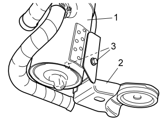
- Install the heater (1) on the bracket (2.) Use the screws (3) from the kit. Tighten the screws.
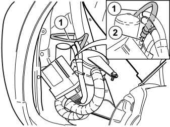
- Position the heater for installation
- Take a small hose clamp for the fuel line from the kit. Install the hose clamp on the fuel hose (1) from the fuel pipe on the sub-frame
- Press the fuel line on the inlet (2) on the fuel pump (FP). Tighten.
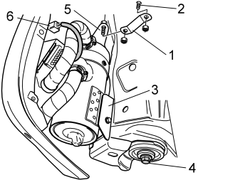
- Position the bracket (1) (from the kit) on the screw (2) protruding in the wheel arch
- Take a nut from the kit. Finger tighten
- Install the heater and the bracket (3) in the left front mounting on the sub-frame. Use the screw (4) from the kit. Finger tighten
- Turn the bracket (1) so that its hole is aligned with the screw underneath the hole in the bottom of the bracket (5)
- Secure both the brackets using the screw and nut from the kit. Finger tighten
- Check that the heater does not catch on any surrounding components
- Tighten the heater to the sub-frame and the brackets
- Tighten the screw (4). Tighten to 105 Nm (78 lbf.ft). Angle-tighten 120° or MAX 280 Nm (206 lbf.ft.)
- Remove the protective cover from the pre-routed connector (6). Press in the catches on the top of the connector to release the cover
- Connect the cable from the heater to the connector
- Remove the jack.
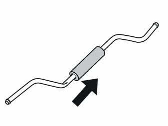
- Take the joint cover and the short fuel line from the kit
- Install the cover on the pipe.
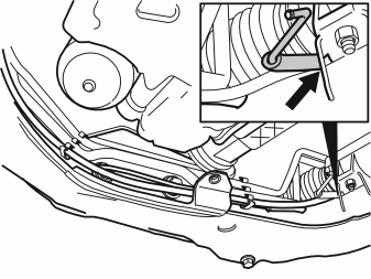
- Insert the end of the fuel line, which is bent in two places, under the power steering and the anti-roll bar, on top of the rear right corner on the sub-frame.
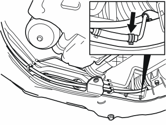
- Take a hose clamp from the kit. Thread the hose clamp onto the short fuel line on the fuel pipe on the sub-frame
- Connect the short fuel pipe to the fuel line. Slide the pipe into the fuel line. Slide the pipe in so far that the two pipes are in contact with each other. This prevents air pockets from forming
- Squeeze the hose clamp together.
Illustration A
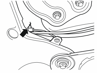
- Take a tie strap from the kit. Clamp the protective tube at the fuel pipe so that it is securely installed.
Illustration B
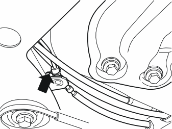
- Take a hose clamp from the kit. Thread the hose clamp onto the fuel line leading to the fuel pump (FP) that was routed previously
- Connect the fuel line to the short fuel pipe. Slide the pipe into the fuel line. Slide the pipe in so far that the two pipes are in contact with each other. This prevents air pockets from forming
- Ensure that the fuel line is routed correctly. Ensure that the fuel line does not obstruct the plastic hose or rub against the sub-frame or other components
- Squeeze the hose clamp together.
Примечание: Fuel lines and fuel pipes must be at least 15 mm (19/32”) from brake pipes.
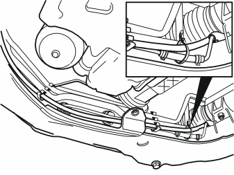
- Take a tie strap from the kit and clamp the fuel pipe at the plastic hose.
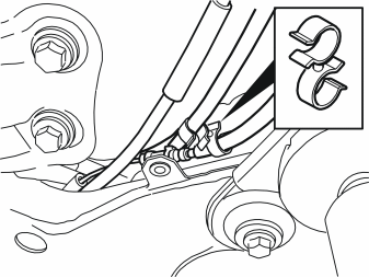
- Take a double clamp from the kit and clamp the fuel line for the parking heater at the ordinary fuel line.
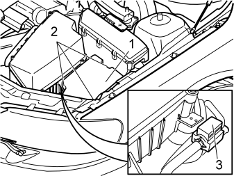
- Remove the cover (1) by pulling off the three clips (2) one at a time
- Detach the vacuum hoses from the holder (3) and the mounting for the air cleaner.
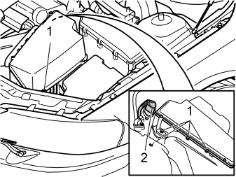
- Unscrew the five screws (1) for the air cleaner
- Disconnect the mass air flow (MAF) sensor connector (2)
- Unscrew the hose clamp from the engine intake manifold
- Pull the air cleaner off the intake manifold
- Cover the inlet for the engine intake manifold.
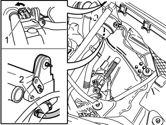
- Release the quick-release connector on the left heater hose (1) for the passenger compartment heater. Press in the circlip on the quick-release connector opposite the two arrow heads. At the same time, turn the circlip in the direction indicated by the arrow. Turn the quick-release connector a little and pull it out
- Disconnect the heater hose (2) on the left-hand side of the cylinder head
- Place the heater hose to one side. It will not be reused.
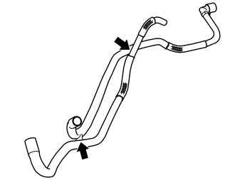
- Take the hose unit from the kit. Cut the two hoses from each other.
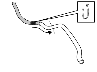
- Pull the guard down on the hose which will be routed to the cowl so that it is in the position illustrated
- Take a tie strap from the kit. Tighten the guard to the hose.
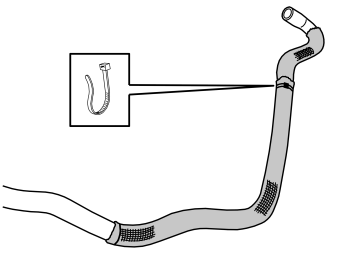
- Pull the long guard on the hose leading the cylinder head up against the short guard nearest the short bend. Ensure that the guards overlap
- Take a tie strap from the kit. Tighten the guard to the hose.
Illustration A
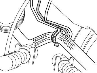
- Take the hose with the quick-release connector from the kit. Route it along the left-hand side member. Route the quick-release connector under the brake pipes and connect it to the cowl panel
- Take a double clamp from the kit. Secure the hose to the second brake line, seen from the front, as illustrated.
Illustration B
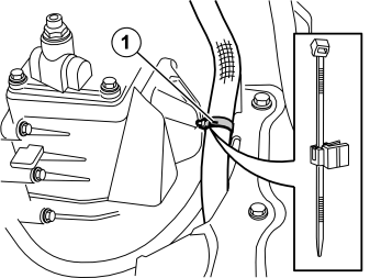
- Take a tie strap and clips from the kit. Clamp the hose to the metal bracket (1)
- Route the free end of the hose to the fuel heater.
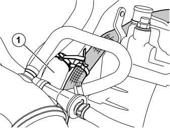
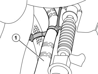
- Take the remaining hose with the angled end from the kit. Route the angled end under the thick coolant hose to the connection on the cylinder head. If necessary, remove the large coolant hose to gain access
- Press the hose onto the connection. Tighten the hose using the existing hose clamp
- Route the other end of the hose down below and around the existing cable harness. Route the hose over the vacuum hose and down to the other routed hose
- Take two double tie straps from the kit. Clamp the hose to the radiator hose (1, illustration A) and the cable casing (1, illustration B). Ensure that the vacuum hose is in its original position.
Осторожно: Secure the hose unit so that it does not rub against any sharp edges or moving parts in the engine compartment.
Connection and finishing work
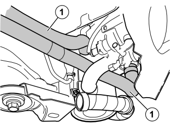
- Connect the two heater hoses (1) to the heater using the hose clamps from the kit. Tighten the hoses.
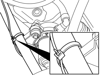
- Take a tie strap from the kit. Clamp the hose with the quick-release connector in place by the mounting as illustrated.
- Tighten the drain nipple on the radiator. Remove the hose
- Reinstall the engine splash guard. Tighten to 25 Nm (18 lbf.ft.)
- Reinstall the centre air baffle and then reinstall the right-hand one
- Fold the wheel arch lining back into position. Secure the wheel arch lining using the two nuts
- Rivet the front edge of the wheel arch lining using the pop rivets from the kit
- Lower the car slightly. Reinstall the wheel. Tighten to 140 Nm (103 lbf.ft.).
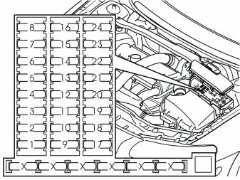
- Open the fuse holder cover in the engine compartment. Install a 25A fuse in position 1
- Reinstall the cover.
- Lower the car completely
- Fill with coolant. Reinstall the expansion tank cap
- Remove the covering from the engine intake manifold
- Reinstall the air cleaner and connections
- Start the engine. Bleed the radiator system.
- Program the software. See the service information in VIDA
- Test the heater function according to separate instructions.
Обсуждение и оценка
0Пока нет комментариев. Будьте первым.