Применимость
| Модель | Двигатель | Год |
|---|---|---|
| S80 (-06) | D5252T MSA 15.8 | 1999–2001 |
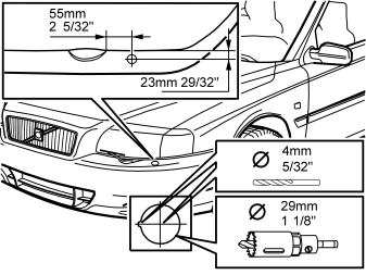
Points 1-4 apply to the S80
- Secure the template sticker. Use the template to mark up the bumper for holes
- Drill a hole using a 4 mm (5/32") diameter drill bit
- Drill a hole at right-angles to the surface. Use a 29 mm (1 1/8") diameter hole saw
- Adjust the guide hole using a round file
- Also adjust the lead-in hole if necessary.
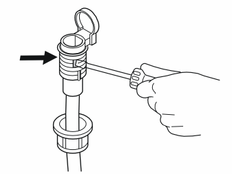
- Open the drain holes on both sides. Use a screwdriver and press in by hand at the markings.
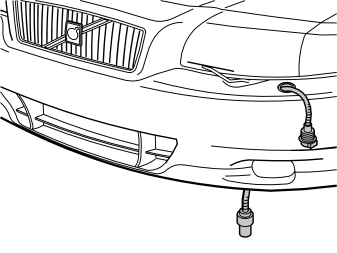
- Install the expander nut in the hole, with the locating pin in the guide hole
- Route the cable, including the ground lead, from the front socket from above and downwards. Let the cables hang down to the ground.
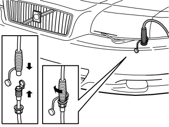
- Connect the cable to the front engine block heater socket
- Press downwards and turn the cable clockwise so that the expander nut engages
- Align the cable from the front socket so that the hinge is pointing towards the headlamp
- Remove the connection cable.
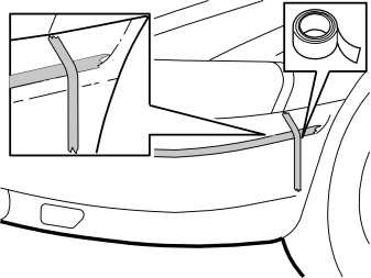
Points 5-9 apply to V70 XC/ XC70
- Clean the bumper cover where the two pieces of tape will be secured
- Install two pieces of tape to mark up the holes for the engine block heater switch (use thin tape). Secure one piece of tape at the rear edge, at the lower corner of the indicator lamp, vertically down. Secure the other piece of tape along the lower edge of the bumper cover radius, as illustrated.
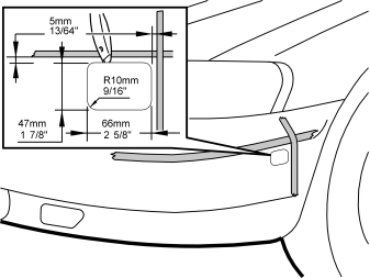
- Install the template (from the kit) on the inside of the corner at the intersection of the two pieces of tape. Leave a distance of 5 mm (13/64") from the edges of the tape
- Apply tape to the surface of the bumper which is to be cut. This is to protect the bumper skin
- Carefully cut out the bumper cover. Follow the template markings. Use a utility knife or similar
- Even off the edges.
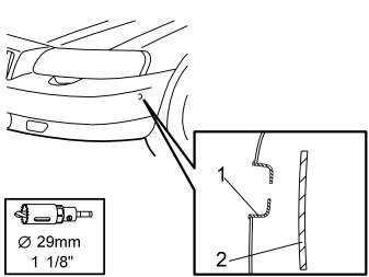
- Remove the pieces of tape
- Take the protective cover (1) for the front engine block heater socket from the kit. Press the protective cover into the cut out. Ensure that the section of the cover where the hole is nearest the edge is pointing forwards
- Mark out the hole in the bracket (2) inside the bumper cover. Use a 29 mm (1 1/8") diameter hole saw without the central drill bit
- Remove the protective cover. Drill out the hole using a 29 mm (1 1/8") diameter hole saw
- Remove any swarf.
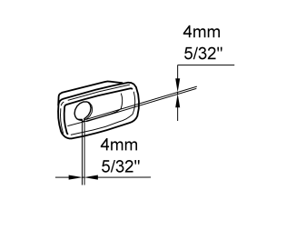
- File out a small 4 x 4 mm (5/32" x 5/32") cut out in the lower edge of the hole in the protective cover. The hole is intended for the lug on the expander nut. This is used to secure the front engine block heater socket
- Reinstall the protective cover.
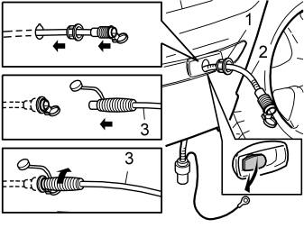
- Install the expander nut (1) in the hole
- Thread the cable supplied (2), including the ground lead, through the hole
- Assemble the supplied connection cable (3) with the cable at the expander nut. Screw clockwise so that the expander nut expands and is secure
- Remove the connection cable.
Примечание: Ensure that the drainage hole for the front engine block heater socket is open.
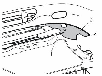
- Raise the car
- Remove the screw (1) from the left air baffle (2) for the front brake
- Pull the left air baffle backwards. Remove the left air baffle
- Remove the right air baffle in the same way.
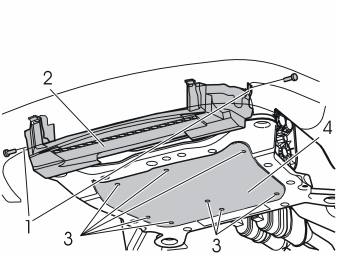
- Slacken off the screws (1). Remove the air baffle (2)
- Remove the screws (3). Remove the splash guard (4).
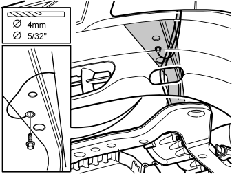
Ground terminal for the cable under the member:
- Drill a hole using a 4 mm (5/32") diameter drill bit
- Rust-proof and secure the ground lead using the 4.8 mm (3/16") flanged screw and toothed washer included.
Примечание: Connect to the side member, not to the sub-frame.
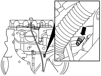
- Open the cover for the radiator expansion tank
- Position a container under the engine. Open the coolant drain cock
- Drain the coolant. Close the drain cock.
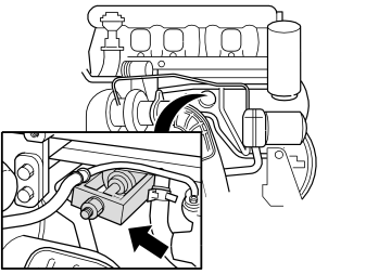
- Pull out the core plug located in the middle of the cylinder block. Use an extractor.
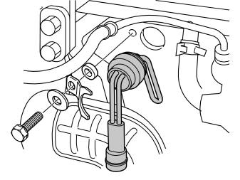
- Thread the O-ring on to the heater
- Lubricate the O-ring using low temperature grease (P/N 1161427)
- Install the heater on the block
- Install the mounting bracket as illustrated. Tighten to 50 Nm (37 lbf. ft.)
- Secure the cable at the pipe on the right-hand side at the rear edge of the sub-frame. Use a tie strap from the kit.
Примечание: Wiring must not be secured to the drive shaft, air conditioning (A/C) pipes, fuel pipes or brake pipes. Ensure that the secured wiring is not rubbing against any sharp edges and that it is not too close to the turbocharger (TC) or exhaust pipe to prevent damage from radiant heat.
Illustration A
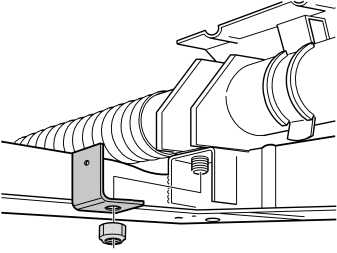
Applies when only installing the engine block heater
- Remove the existing nut from the steering gear
- Install the mounting bracket for the junction switch and cables
- Install the new lock nut supplied. Tighten to 48 Nm (36 lbf. ft.)
- Secure the first tie strap on the power steering pipe. If there is no servo coolant pipe; drill out the first hole to a diameter of 6.5 mm (1/4"). Secure the tie strap as normal.
Примечание: Wiring must not be secured to the drive shaft, air conditioning (A/C) pipes, fuel pipes or brake pipes. Ensure that the secured wiring is not rubbing against any sharp edges and that it is not too close to the turbocharger (TC) or exhaust pipe to prevent damage from radiant heat.
Illustration B
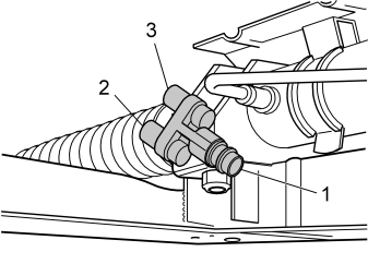
Applies when installing the engine block heater and passenger compartment socket together
- Install the Y connector on the bracket. Use the screw and nut from the kit
- Lubricate the O-rings. Use low temperature grease (P/ N 1161427)
- Connect the wiring from the front engine block heater socket (1), the passenger compartment socket (3) and the engine block heater (2) to the Y-connector
- Tighten the Y connector and the bracket on the steering gear. Tighten to 48 Nm (36 lbf. ft).
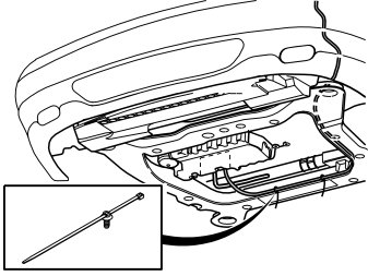
- Route the cable from the bumper to the cable from the engine block heater. See the illustration
- Secure the cable using tie straps in the existing holes
- Connect the cable from the bumper to the cable from the engine block heater. Alternatively connect the cable from the bumper to the Y connector.
Примечание: Wiring must not be secured to the drive shaft, air conditioning (A/C) pipes, fuel pipes or brake pipes. Ensure that the secured wiring is not rubbing against any sharp edges and that it is not too close to the turbocharger (TC) or exhaust pipe to prevent damage from radiant heat.
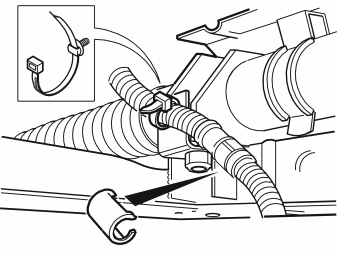
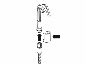
- Install the locking sleeves over all the connectors and cable splices on the wiring. Ensure that they are correctly installed.
- Reinstall the air baffles and the splash guard. See points 11 and 12
- Tighten the screws for splash guard. Tighten to 25 Nm (19 lbf. ft)
- Clamp the engine heater cable in the mounting on the left-hand side of the air baffle.
- Fill with coolant. Run the engine to operating temperature.
Обсуждение и оценка
0Пока нет комментариев. Будьте первым.