Применимость
| Модель | Двигатель | Год |
|---|---|---|
| S60 (-09) | B5254T4 | 2004–2007 |
| V70 (00-08) | B5254T4 | 2004–2007 |
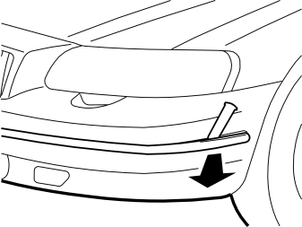
- Remove the bumper guard. Loosen the guard at one end using a thin plastic blade and pull it off.
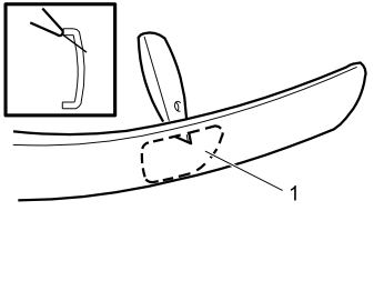
- Cut a hole (1) in the bumper guard as marked at the rear of the strip. Use a carpet knife or similar tool and allow a certain margin.
Примечание: When cutting along the upper horizontal line, lean the knife against the upper edge of the strip as a guide to ensure that the cut is precisely in the middle of the rounded section.
- Smooth the edges of the hole with a file.
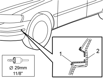
- Fit the protective cover (1) for the front intake in the bumper guard
- Place the guard in position but do not secure at this point
- Mark out the hole in the bumper cover (2) with the aid of a 29 mm (1 1/8”) hole saw and centre bit
- Remove the bumper guard and protective cover and cut the hole with the same hole saw.Ø29 mm (11/8”)
- Remove the swarf
- Refit the bumper guard, with the protective cover, and press home firmly.
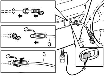
- Install the expander nut (1) in the hole
- Thread the accompanying cable (2), including the ground cable, through the hole
- Assemble the connecting cable (3) from the kit with the expander nut cable. Turn clockwise so that the expander nut expands
- Remove the connecting lead.
Примечание: Ensure that the front intake drain is open.
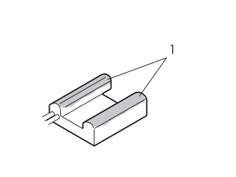
- Apply heat conducting compound (P/N 9499205) to the surfaces (1) of the heater body in contact with the cylinder block.
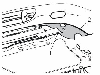
- Jack up the car
- Remove the screw (1) in the left front brake air baffle (2)
- Pull the baffle backward to remove
- Remove the right front brake air baffle in similar manner.
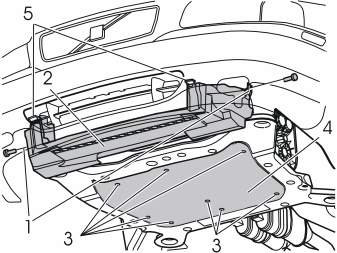
- Slacken the screws (1) and remove the air baffle (2)
- Slacken the screws (3) and remove the guard plate (4).
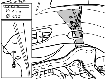
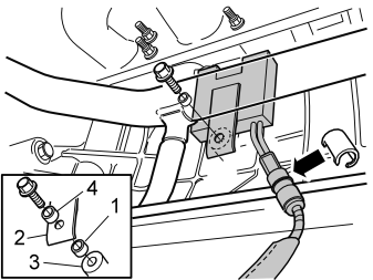
Ground connection for cable under member
- Drill a 4 mm (5/32") hole
- Apply rust protection and connect the ground cable using the 4.8 mm (3/16") flanged screw and serrated washer supplied.
Примечание: Connect the ground cable to the side member, not to the subframe.
- Tie up excess cable using new tie clips.
Fig. A
- Clean the heater location to ensure the best possible transfer of heat to the cylinder block. Also clean the internal thread
- Slide the heat shield over the heater cable
- Take the sealing sleeve and heater cable from the kit. Connect the cable to the heater and fit the sleeve over the joint in the cable
- Mount the heater on the cylinder block as illustrated
- Fit the spacer (1) (t = 10 mm / 25/64") between the clamp (2) and bracket (3) on the cylinder block
- Fit the outer spacer (4) (t = 32 mm / 1 1/4”) to the outer side of the clamp (2)
- Tighten the heater in position using the screw supplied. Torque to 16 Nm (12 lbf.ft.).
Fig. B
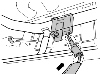
- Pull the heat shield all the way up to the heater so that the joint and plastic moulding are covered completely.
Примечание: It is important that the heat shield covers the entire joint with the engine.
- Secure the heat shield around the heater cable using a gray, heat-resistant tie clip around the bottom of the shield.
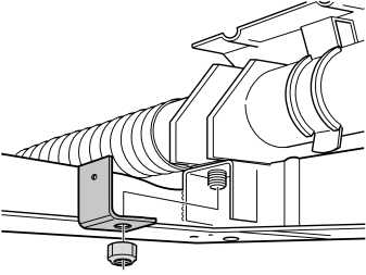
Applies when heater only is installed
- Remove the existing nut from the steering box
- Fit the bracket for mounting a branch connector and cables
- Fit the locknut from the kit and torque to 48 Nm (36 lbf.ft.)
- Attach the first tie clip to the power steering line. In the absence of a servo fluid cooling line, drill out the first hole to 6.5 mm (1/4") and attach the tie clip as normal.
Примечание: Cables must not be attached to drive shafts, or to A/C, fuel or brake lines. Ensure that clipped cables are not rubbing against sharp edges, or are not positioned too close to a turbo or exhaust pipe due to the risk of heat radiation.
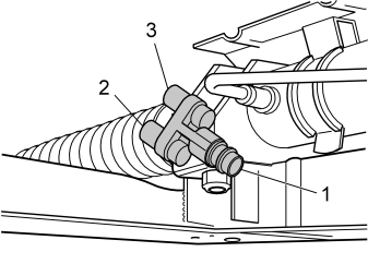
Applies when both engine heater and in-vehicle outlet are installed
- Mount the branch connector on the bracket using screws and nuts from the kit
- Lubricate the O-rings with low-temperature grease (P/N 1161427)
- Connect the cables from the front intake (1), in-vehicle outlet (3) and engine heater (2) to the branch connector
- Torque the branch connector and bracket on the steering box to 48 Nm (36 lbf.ft.).
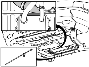
Applies to engine heater as illustrated
- Run the cable from the bumper to the heater cable as illustrated
- Secure the cable with tie clips using the existing holes and the oil cooler lines
- Connect the cable from the bumper to the heater cable or to the branch connector.
Примечание: Cables must not be attached to drive shafts, or to A/C, fuel or brake lines. Ensure that clipped cables are not rubbing against sharp edges, or are not positioned too close to a turbo or exhaust pipe due to the risk of heat radiation.
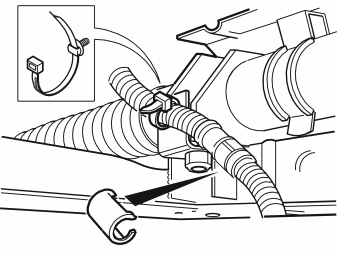
- Fit sealing sleeves over all cable connectors and joints, ensuring that these are correctly located.
- Refit the air baffles and guard plate as per items 6 and 7
- Torque screws to 80 Nm (60 lbf.ft.), and screws and nuts to 60 Nm (43 lbf.ft.)
- Secure the servo hose to the cross strut using a tie clip from the kit.