Применимость
| Модель | Двигатель | Год |
|---|---|---|
| S80 (07-) | D4204T | 2008–2010 |
| V70 (08-) | D4204T | 2008–2010 |
Примечание: Some steps in these installation instructions are presented with illustration only.
Installing the front engine block heater socket
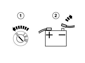
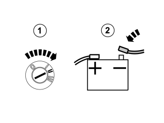
- Turn the ignition key to position 0.
- Disconnect the battery negative lead.
Примечание: Wait at least three minutes before disassembling the connectors or removing other electrical equipment.
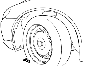
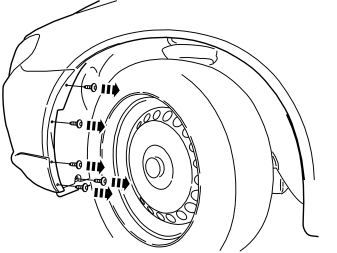
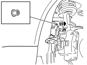
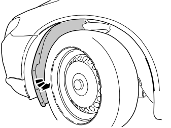
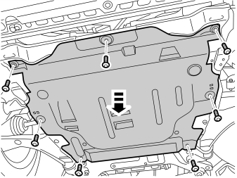
Applies to the S80
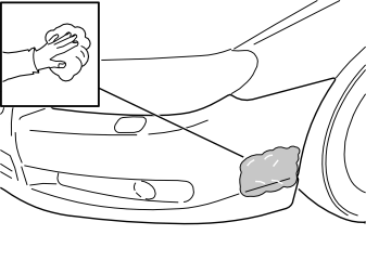
- Use isopropanol to clean the bumper cover where the cutting template for the front engine block heater socket is to be secured.
- Wipe dry.
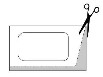
- Take the template from the kit and cut it along the dotted lines.
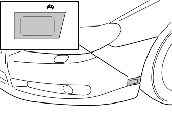
- Remove the protective backing tape from the template and secure the template edge to edge with the front edge of the front wing and embossing in the bumper cover as illustrated.
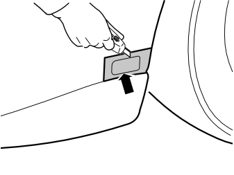
- Using a sharp knife, first make a thin cut along the edges of the inside of the template. This provides a groove to follow. Then carefully cut the bumper cover.
Примечание: Cut carefully. It is easy to slip with the knife and move outside the template.
- Remove the template and tape pieces.
- Install the protective cover for the front engine block heater socket from the kit. Check that it aligns. Adjust the hole using a knife or file as necessary.
- Smooth off the hole edges. Remove any swarf.
Applies to the V70
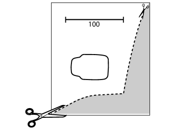
- Find the template for the front intake in the installation instructions. Cut it out following the dotted lines.
Примечание: Check the scale.
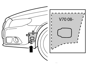
- Attach the template using tape edge to edge with front edge of the front wing and the embossing in the bumper cover as illustrated.
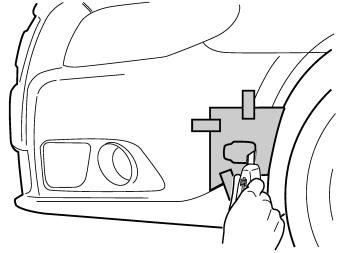
- Take a sharp knife. First make a thin cut along the edges of the inside of the template. This provides a groove to follow. Then cut carefully out of the bumper cover.
Примечание: Cut carefully. It is easy to slip with the knife and move outside the template.
- Remove the template.
- Install the protective cover for the front engine block heater socket from the kit. Check that it aligns. Adjust the hole using a knife or file as necessary.
- Smooth off the hole edges. Remove any swarf.
Applies to all models
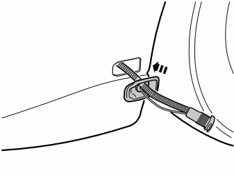
- Press the protective cover (from the kit) into place in the hole cut in the bumper cover.
- Take the cable for the front engine block heater socket with ground lead from the kit and thread them through the protective cover.
Illustrations A and B
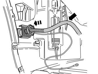
- Install the attaching brace and nut from the kit.
- Rotate the connector for the front engine block heater socket so that the cover opens backwards (Illustration B).
- Plug the electrical connector into the front engine block heater socket. Use the connector as a counterhold when tightening.
- Tighten the front engine block heater socket to the bumper shell.
- Press the cable into the holder on the washer fluid reservoir.
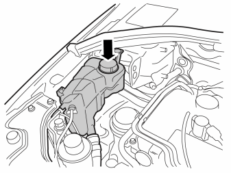
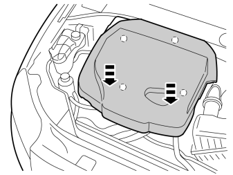
- Remove the cover on the radiator expansion tank.
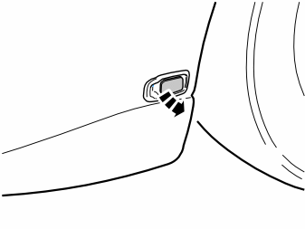
Illustrations A and B
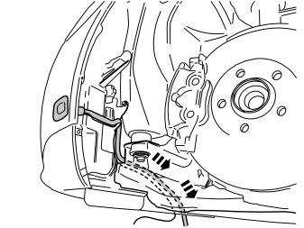
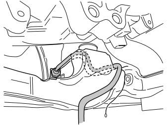
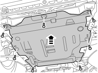
- Route the cable with the ground cable from the front engine block heater socket in front of the left-hand front mounting for the subframe and down on the inside of the subframe.
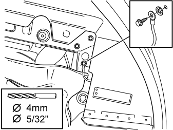
- Drill a Ø 4mm (Ø 5/32 ") hole for the front intake grounding on the underside of the left front side member as illustrated.
- Deburr the hole edges, remove the drill swarf and apply rustproofing agent.
- Take a screw and toothed washer from the kit. Tighten the ground cable.
Installing the engine block heater
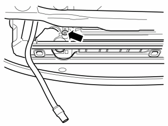
- Drain the coolant.
- Tighten the nipple after draining.
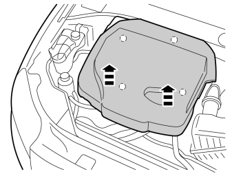
Illustrations A and B
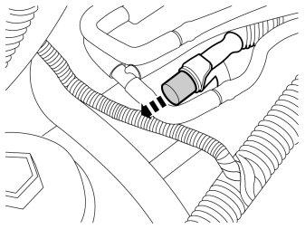
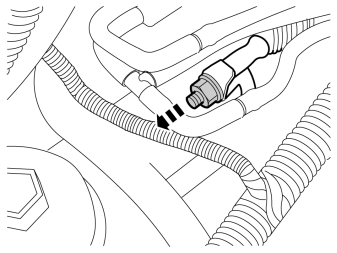
- Remove the protective cover and nut from the battery negative terminal.
- Remove the cable.
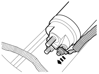
- Remove the M6 nut on the starter motor.
- Remove the cable.
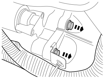
- Remove the two upper screws in the starter motor.
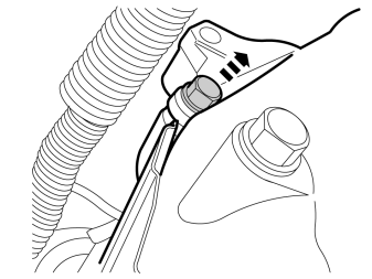
- Remove the lower screw in the starter motor.
- Detach the starter motor and remove it.
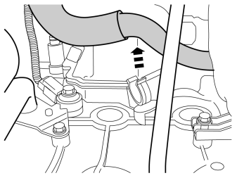
- Remove the radiator hose from its holder. Secure it above the core plug in cylinder number two.
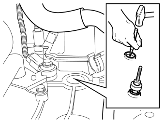
- Hit the middle of the core plug on cylinder number two using a center punch.
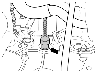
- Use puller, P/N 9512960 to remove the core plug.Install the expander in the core plug and tighten.
Осторожно: Tighten to 10–25 Nm (7–18 lbf. ft.), max. 40 Nm (30 lbf. ft.) . Tightening more than this may damage the expander.
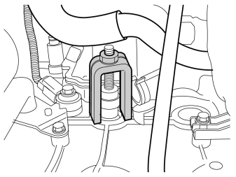
- Install the mounting bracket. Remove the core plug.
Примечание: There may be some coolant left in the engine.
- Position the radiator hose in its clamp.
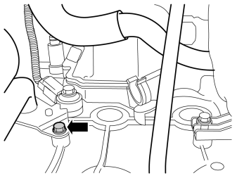
- Remove the screw in the tensioner for the hose connection in cylinder number three.
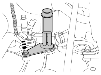
- Lubricate the O-ring on the engine block heater using low temperature grease.
- Press the engine block heater into the hole for the core plug with the angled section of the heating element pointing down.
- Tighten the engine block heater to the engine block using the tensioner and screw from the kit. (the tensioner is positioned above the tensioner).
- Torque tighten the screw to 24 Nm (18 lbf.ft.).
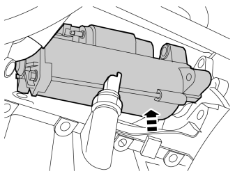
- Reinstall the starter motor.
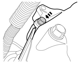
- Tighten the lower screw to 35 Nm (26 lbf.ft.).
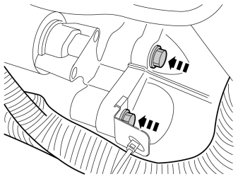
- Tighten the upper screws to 35 Nm (26 lbf.ft.).
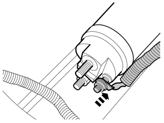
- Connect the cable to the starter motor. Torque tighten the nut to 6 Nm ( 4.5 lbf.ft.).
Illustration A
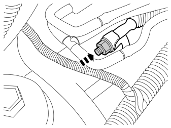
- Connect and tighten the positive cable to the battery. Torque tighten the nut to 12 Nm ( 9 lbf.ft.).
Illustration B
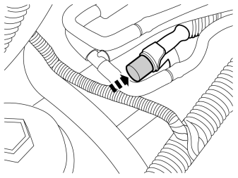
- Press the protective cap into place over the nut to the positive cable.
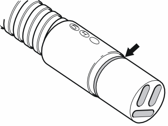
- Lubricate the O-rings on all cables for the engine block heater and if the car is to have a passenger compartment connector/timer relay, also lubricate the O-rings on these with low temperature grease.
Примечание: Do not get any grease on the surfaces of the connector.
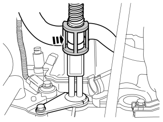
- Connect the joint cable from the kit to the engine block heater.
- Firmly press the cable junction together. Press a locking sleeve from the kit over the cable junction. Ensure that the cable does not rub against sharp edges or moving parts in the engine compartment.
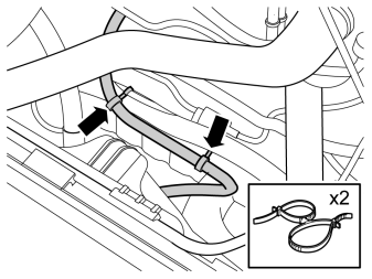
- Route the cable from the heater over and in front of the thick cable harness and allow it to hang.
- Secure it at the thick cable harness using two double cable ties from the kit.
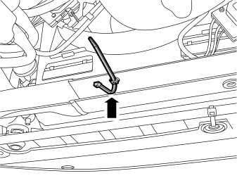
- Take the clip with tie strap for a Ø 6.5 mm (1/4 ") hole and press it into the left hole on the inside of the upper edge of the subframe.
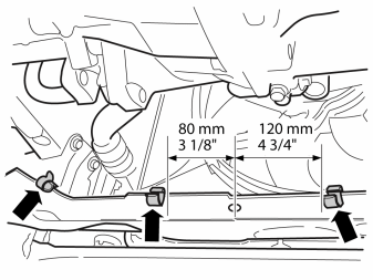
- Take the three clips from the kit. Press them onto the subframe's upper/front edge and at the left front-edge of it.
- Position the two clips that are nearest the tie strap fitted previously following the measurements specified in the illustration.
- Lubricate the O-ring on the contact on the cable from the front intake using low temperature grease.
Примечание: Do not get any grease on the surfaces of the connector.
Illustration A
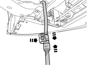
- Connect the extension cable of the engine heater with the cable from the front intake. Press the connectors together and press a locking sleeve from the kit over the splice.
Illustration B
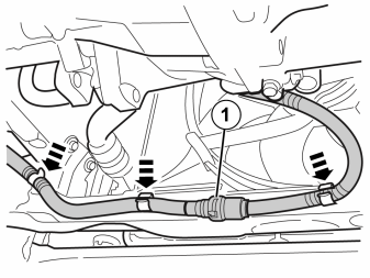
- Clamp the cable splice (1) to the inside of the subframe using the tie strap and press the cable into the clips.
Illustration C
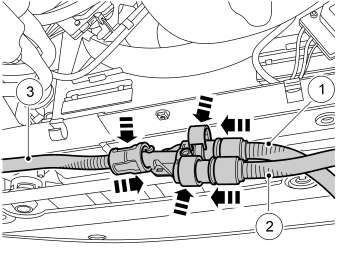
Applies when fitting passenger compartment connector at the same time
- If the passenger compartment connector is to be installed at the same time, install the junction connector now. Lubricate the O-rings on the contacts as previously.
- Connect:
Illustration D
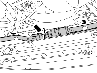
Applies when fitting passenger compartment connector at the same time
- Insert the junction connector in the space in the subframe. Secure the junction connector by fastening the cable tie through the rear hole of the connector.
If the passenger compartment connector socket shall be installed at the same time then install the junction connector now in accordance with illustration C and D, and connect the cables to it.
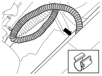
- If there is too much slack in the cable at the hose to the turbo, take the remaining clips and press onto the lower flange on the front edge of the subframe.
- Press the cable into the clip.
Finishing work
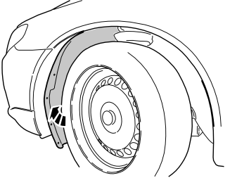
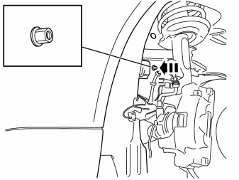
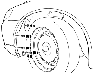
- Fill with coolant and warm up the engine. Bleed the cooling system and check for leaks. Top up the cooling system as necessary.
Обсуждение и оценка
0Пока нет комментариев. Будьте первым.