Применимость
| Модель | Двигатель | Год |
|---|---|---|
| S40 (04-) | B4164S3 | 2005–2011 |
| V50 | B4164S3 | 2005–2011 |
Installing the front engine block heater socket
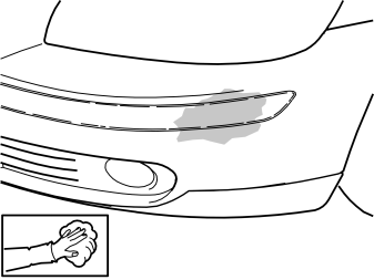
- Clean the bumper cover. Use a mixture of 30% windscreen washer fluid and 70% water. Clean where the cutting template for the front engine block heater socket is to be secured.
- Wipe dry.
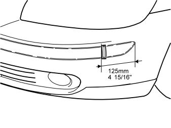
- Apply a piece of tape vertically to the bumper cover. See the illustration.
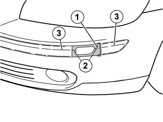
- Remove the backing tape on the template from the kit.
- Press the template onto the embossing on the bumper cover. The marking (1) on the template must be opposite the front edge of the tape. The marking (2) on the template must be in line with the curve (3) at the top edge of the embossing on the bumper cover.
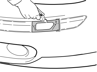
- Take a sharp knife. First make a thin cut along the edges of the inside of the template. This provides a groove to follow. Then cut carefully out of the bumper cover.
Примечание: Cut carefully. It is easy to slip with the knife and move outside the template.
- Remove the template.
- Install the protective cover for the front engine block heater socket from the kit. Check that it aligns. Adjust the hole using a knife or file as necessary.
- Smooth off the hole edges. Remove any swarf.
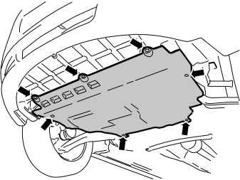
- Remove the seven screws holding the engine splash guard and remove the guard.
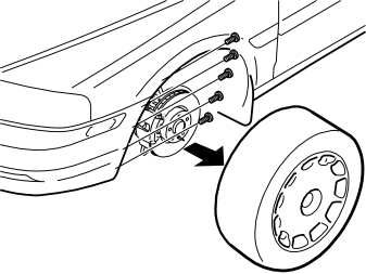
- Remove the left front wheel.
- Remove the five screws holding the bumper cover in the wing liner on the left and right-hand sides.
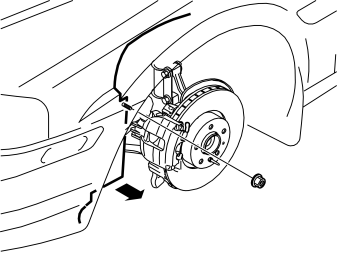
- Remove the nut holding the left-hand wing liner to the front member.
- Bend the front edge of the left-hand wing liner up over the brake calliper.
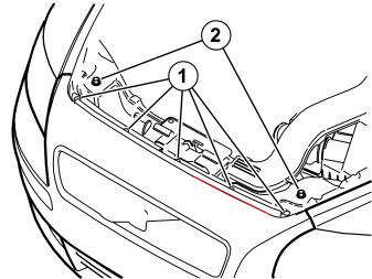
- Push in the centre of the five clips (1). Remove the clips.
- Remove the two screws (2).
Illustration A
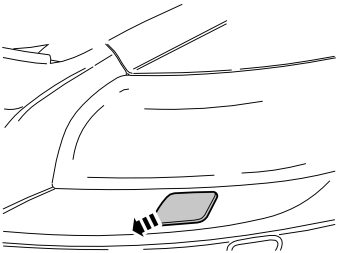
- Remove the covers for the nozzles for the headlamp washers on the right and left-hand sides. Carefully grip the cover. Pull the cover out until the catch becomes accessible.
Illustration B
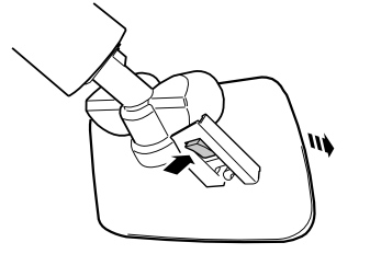
- Press the catch up. Remove the cover. Do not damage the painted surfaces or the washer nozzles.
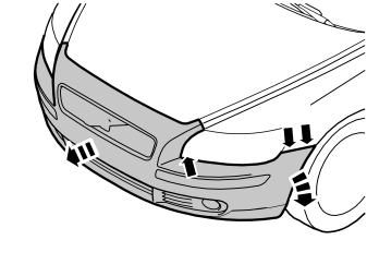
- Detach the ends of the bumper cover on the left and right-hand sides. Grasp the end of the bumper cover inside the wing liner. Carefully pull the end of the bumper cover so that the two catches on the inside release.
- Remove the bumper cover and air baffle. Pull the bumper cover and air baffle forwards until the remaining catches under the lamps release.
- Disconnect the connectors for the fog lamps if applicable.
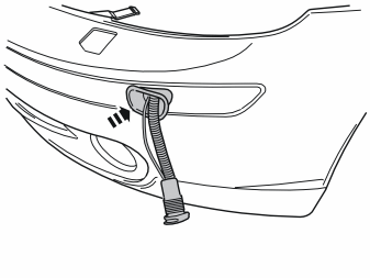
- Press the protective cover (from the kit) into place in the hole cut in the bumper cover.
- Insert the cable for the front engine block heater socket together with the ground lead from the kit through the protective cover.
Illustration A
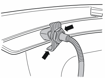
- Install the mounting and nut from the kit. Connect the connector to the front engine block heater socket. Use the connector as a counterhold when tightening.
Illustration B
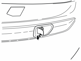
- Turn the connector for the front engine block heater socket so that the cover opens forwards. Tighten the front engine block heater socket to the bumper cover.
Cable routing
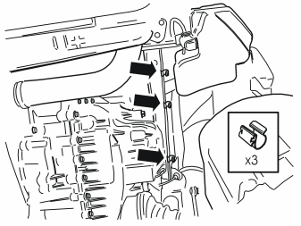
- Install three clips from the kit on the panel edge on the underside of the left front member.
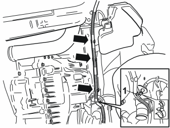
- Reinstall the bumper cover. Use the five clips and the two screws at the top edge. Ensure that the air baffle is correctly positioned in its mounting.
- Reconnect the connectors for the fog lamps if applicable.
- Press the ends of the bumper cover into place on the body.
- Route the cable for the front engine block heater socket from the front edge of cover for the control module, along the underside of the front member and over the drive shaft.
- Press the cable into the previously installed clips.
- Clamp the cable to the brake pipe using the double clamp (1) from the kit.
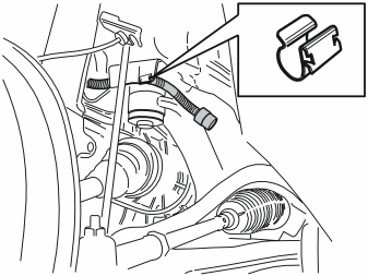
- Take a clip from the kit. Press the clip into place at the edge of the panel. See the illustration.
- Press the cable into the clip.
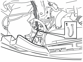
- Clamp the cable in the hole in the bracket for the front left radiator mounting. Use a tie strap (1) from the kit.
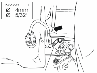
- Drill a Ø4 mm (5/32 ”) hole for the ground lead, on the outside of the left-hand front member, approximately as illustrated.
- Remove any swarf.
- Treat the edges of the holes using a rust-proofing agent.
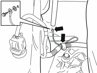
- Secure the ground lead in the drilled hole. Use the screw and toothed washer from the kit.
- Secure the excess ground lead at the clamp for the heater cable.
Installing the engine block heater
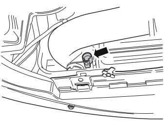
- Remove the cover on the radiator expansion tank.
- Unscrew the drain nipple in the left-hand bottom edge of the radiator. Drain the coolant.
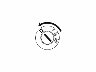
- Turn the ignition switch to position 0.
Примечание: Wait at least five minutes before unplugging the connectors, detaching the battery leads or removing other electrical equipment.
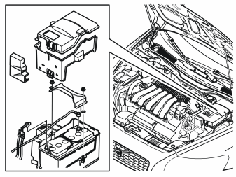
Remove:
- the battery box cover
- the battery negative lead
- the battery positive lead
- the two covers for the battery box
- the two nuts and remove the mounting bracket
- the battery.
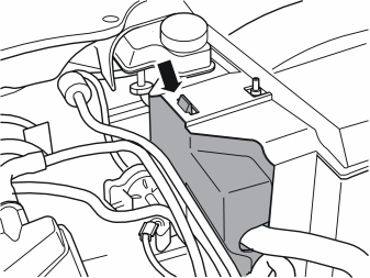
- Remove the cover to the control module on the right-hand side of the battery box.
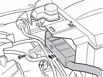
- Remove the screw in the connector for the control module and pull it out.
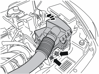
- Detach the rubber strap to the air cleaner mounting.
- Detach the pipe to the crankcase ventilation.
- Fold up the air cleaner so that the battery box can be removed.
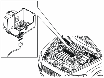
- Remove the battery box, and detach the connector to the sensor underneath at the same time.
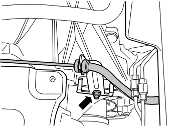
- Remove the nut to the bracket for the hose/pipe to the clutch slave cylinder on the gearbox, and remove the bracket with hose/pipe.
Illustration A
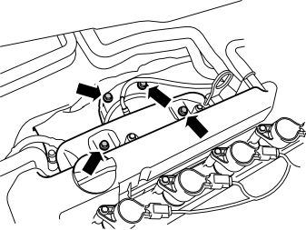
- Remove the four screws to the heat deflector plate above the manifold.
Illustration B
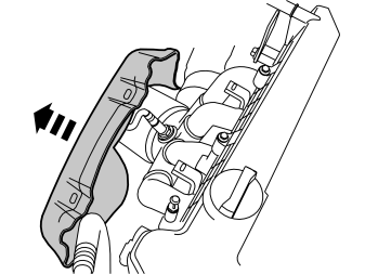
- Fold away the heat deflector plate from the left-hand side of the manifold.
Примечание: Be careful with the cable to the heated oxygen sensor.
- Detach the connector to the heated oxygen sensor as required.
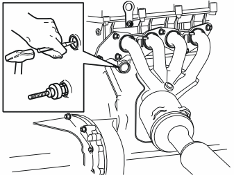
- Gently tap the centre of the frost plug using a centre punch. Use puller, P/N 9814218 to remove the frost plug.
- Install the expander in the core plug and tighten.
Осторожно: Tighten to 10-25 Nm (7-18 lbf. ft.), max. 40 Nm (30 lbf. ft.). Tightening more than this may damage the expander.
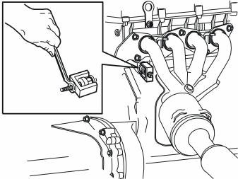
- Install the mounting bracket. Remove the core plug.
Примечание: There may be some coolant left in the engine.
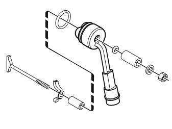
- Fit the engine block heater. See the illustration.
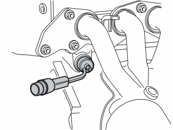
- Lubricate the large O-ring on the engine block heater using low temperature grease, (P/N 1161417-9).
- Unscrew the nut to the end of the threads on the threaded section of the heater.
- Fit the element in the engine block by angling and turning it into position. See the illustration.
- Tighten the nut manually and angle the heater approximately as much as in the illustration.
- Tighten the nut, tightening torque 3.5 Nm (3 lbf. ft.).
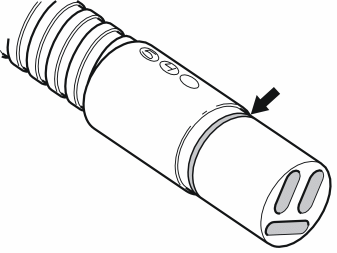
- Grease the O-rings on all the engine block heater cables using low temperature grease (P/N 1161417-9). If the car is to have a passenger compartment connector socket/junction connector/timer relay, also grease the O-rings on these components.
Примечание: Do not get any grease on the surfaces of the connector.
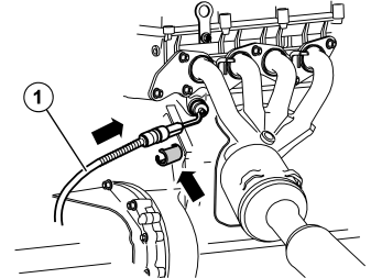
- Connect the cable (1) from the kit to the engine block heater.
- Firmly press the cable junction together. Press a locking sleeve from the kit over the junction. Ensure that the cable does not rub against sharp edges or moving parts in the engine compartment.
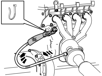
- Take the heat deflector hose from the kit and cut it to a length of 200 mm (7 7/8").
- Thread the heat deflector hose onto the cable so that it completely covers the cable junction on the heater.
- Take the grey tie strap from the kit and clamp the upper edge of the heat deflector hose firmly.
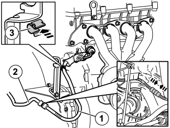
- Refit the bracket, with the pipe/hose to the clutch, on the gearbox. Torque tighten the nut to 24 Nm (18 lbf. ft.).
- Pull the cable (1) from the engine block heater, over the gearbox and on to the drive shaft where the front socket cable (2) is located.
- Press in a clamp (3) from the kit to the edge of the bracket for the pipe/hose to the clutch.
- Press the cable into the clamp.
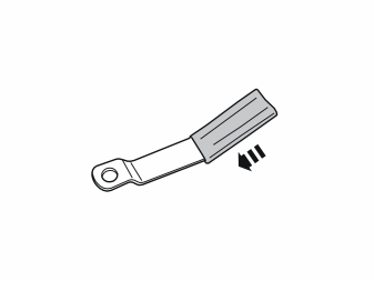
Applies to cars where the engine block heater and/or passenger compartment connector socket/timer relay are mounted at the same time
- Take the bracket and the rubber guard from the kit for the passenger compartment connector socket. Press the rubber guard on to the bracket.
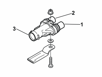
Applies to cars where the engine block heater and passenger compartment connector socket are installed at the same time
- Tighten the junction connector at the bracket (included in the kit for the passenger compartment connector socket) in the position illustrated. Use the screw, toothed washer and nut from the kit. The bracket must be parallel to the length of the junction connector.
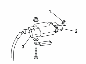
Applies to cars where the engine block heater and timer relay are installed at the same time
- Tighten the timer relay at the bracket (purchased separately) in the position illustrated. Use the screw, toothed washer and nut from the kit. The bracket must be parallel to the length of the timer relay.
- Connect the connector on the long cable harness (from the kit) to the timer relay.
- Press the rubber plug (1), P/N 346509, (purchased separately) into place on the free socket in the timer relay Use butyl tape to secure the rubber plug.
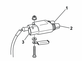
Applies to cars where the passenger compartment connector socket and the timer relay are installed at the same time
- Tighten the timer relay at the bracket (purchased separately) in the position illustrated. Use the screw, toothed washer and nut from the kit. The bracket must be parallel to the length of the timer relay.
- Connect the connector on the long cable harness (from the kit) to the timer relay.
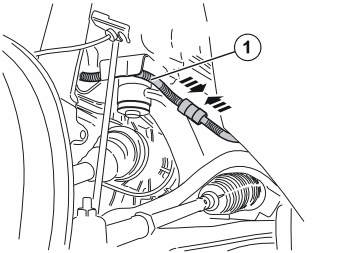
- Connect the short cable from the kit to the engine block heater, to the routed cable (1) from the front socket. (When fitting junction connector/timer relay at the same time, the cable from the front socket is connected to the single outlet on the junction connector/timer relay instead. Refer to the installation instructions for passenger compartment socket/timer relay).
- Firmly press the cable junction together.
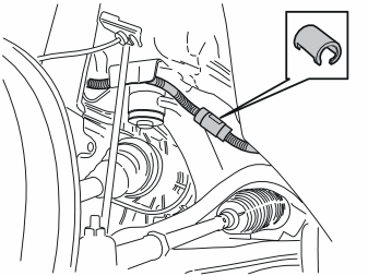
- Press a locking sleeve (from the kit) over the cable splice.
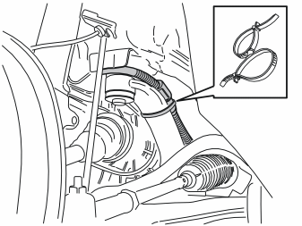
- Take a double tie strap from the kit. Install the double tie strap around the stay and the cable splice. Ensure that the splice is secured in the centre of the strut. Tighten the double clamp properly.
Bleeding and filling the cooling system Illustration A
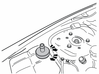
- Install adapter P/N 9512955 in the expansion tank. Tighten.
Illustration B
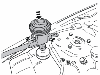
- Install the bleed kit P/N 9512957 on the connection nipple for the adapter.
Illustration C
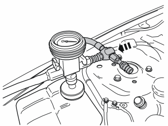
- Bleed and fill the cooling system. See the manual for the bleed kit.
- Refit the heat deflector plate and torque tighten the screws to 10 Nm (7 lbf. ft.).
- Reinstall the left-hand wing liner. Tighten the wing liner to the left-hand side member.
- Tighten the two wing liners to the bumper cover on the right and left-hand sides.
-
Refit the covers to the nozzles for the headlamp high-pressure washers.
-
Attach the connector to the sensor in the bottom of the battery box and refit it. Tighten it with the three screws and torque tighten to 10 Nm (7.5 lbf. ft.).
- Refit the air cleaner and tension it with the rubber strap. Make sure that the intake manifold underneath fits correctly at the bottom on the air cleaner connection.
- Connect the pipe to the crankcase ventilation.
- Refit the connector to the control module and tighten the screw to 3 Nm (2 lbf. ft.).
- Refit the cover over the control module.
- Reinstall the battery.
- Refit the mounting bracket over the battery. Tighten it with the two nuts and torque tighten to 10 Nm (7.5 lbf. ft.).
- Refit the two covers for the battery box.
- Turn the ignition key to position II.
- Connect the battery positive lead and then its negative lead. Torque tighten the nuts to 2.5 Nm (2 lbf. ft.).
- Refit the battery box cover.
- Test drive and check that there are no leaks.
- Reinstall the engine splash guard.
- Reinstall the front wheel. Tighten the wheel nuts. Tighten to 90 Nm (66 lbf. ft.).
Обсуждение и оценка
0Пока нет комментариев. Будьте первым.