Применимость
| Модель | Двигатель | Год |
|---|---|---|
| S60 (-09) | B5204T5 | 2001–2009 |
| S60 (-09) | B5234T3 | 2001–2004 |
| S60 (-09) | B5234T7 | 2001–2004 |
| S60 (-09) | B5244S | 2001–2009 |
| S60 (-09) | B5244S2 | 2001–2009 |
| S60 (-09) | B5244S6 | 2003–2006 |
| S60 (-09) | B5244T3 | 2001–2003 |
| S60 (-09) | B5244T4 | 2005, 2006 |
| S60 (-09) | B5244T5 | 2005–2009 |
| S60 (-09) | B5254T2 | 2003–2009 |
| S60 (-09) | B5254T4 | 2004–2007 |
| V70 (00-08) | B5204T5 | 2000–2007 |
| V70 (00-08) | B5234T3 | 2000–2004 |
| V70 (00-08) | B5234T7 | 2001–2004 |
| V70 (00-08) | B5244S | 2001–2008 |
| V70 (00-08) | B5244S2 | 2001–2008 |
| V70 (00-08) | B5244S6 | 2003–2006 |
| V70 (00-08) | B5244T3 | 2000–2003 |
| V70 (00-08) | B5244T4 | 2005 |
| V70 (00-08) | B5244T5 | 2005–2007 |
| V70 (00-08) | B5254T2 | 2003–2008 |
| V70 (00-08) | B5254T4 | 2004–2007 |
| V70 (00-08) | D5252T MSA 15.8 | 2000, 2001 |
| V70 XC (01-) / XC70 (-07) | B5234T7 | 2001–2004 |
| V70 XC (01-) / XC70 (-07) | B5244T3 | 2001, 2002 |
| V70 XC (01-) / XC70 (-07) | B5244T4 | 2005, 2006 |
| V70 XC (01-) / XC70 (-07) | B5254T2 | 2003–2007 |
| XC90 | B5254T2 | 2003–2012 |
| XC90 | B5254T9 | 2013, 2014 |
Примечание: - Steps 1-10, 19 and 36-51 apply to the S60 and V70.
- Steps 11-19 and 36-51 apply to the XC90 up to and including model year -2006 (CH -327999).
- Steps 20-51 apply to the XC90 from model year 2007- (CH 328000-).
- Other model year delimitations:
Applies to the S60 and V70 up to and including model year -2004
Preparations
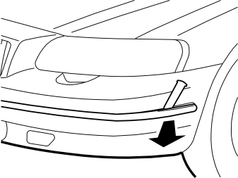
- Remove the overrider molding from the bumper by prizing up the molding at one corner using a weatherstrip tool, and then pull the whole molding away.
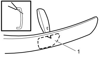
- Cut holes in the overrider molding according to the marking (1) on the back of the molding using a utility knife or similar. Cut with a margin and fine tune using a file.
Примечание: When cutting along the upper horizontal line, angle the knife towards the upper edge of the molding. Guide the knife along the molding. This is so that the cut is not positioned in the center of the curvature of the molding.
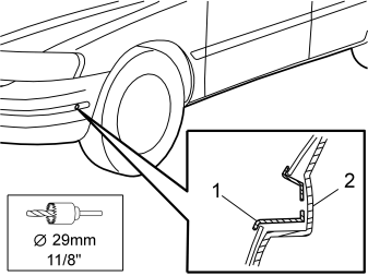
- Reinstall the overrider molding.
- Install the front socket's protective cover (1) in the overrider molding.
- Mark out the hole in the bumper cover (2) using a Ø29 mm (1 1/8") diameter hole saw and its central drill bit.
- Remove the protective cover and drill out with the Ø29 mm (1 1/8") diameter hole saw.
- Remove any swarf.
- Reinstall the protective cover.
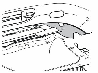
- Raise the car.
Remove:
- the screw (1) from the left-hand air baffle (2).
- the left-hand air baffle by pulling it backwards.
- the right-hand air baffle in the same way.
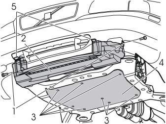
Remove:
- the air baffle (2) by undoing the screws (1), pressing up the catches (5) and moving the air baffle down and back.
- the engine splash guard (4) by undoing the screws (3).
Installing the front engine block heater socket
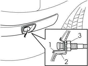
- Route the cable belonging to the front socket through the protective cover (1) and the bumper cover (2).
- Install the plastic nut (3) from the kit on the front socket and tighten. The cover fits horizontally and opens forwards.
Подсказка: The nut is difficult to access. It can be easier to screw in with the cable instead.
- Route the cables down along the left-hand side of the left-hand side member.
Applies to the S60 and V70 from model year 2005–
Preparations
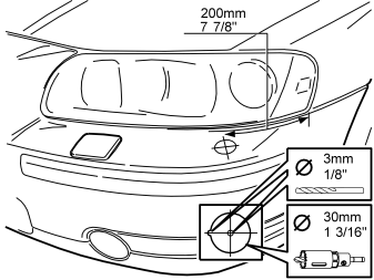
- Measure out the hole for the front socket as illustrated. The measurement between the center of the hole and the corner of the headlamp must be 200 mm (7 7/8"). Measure out the hole's center so that it is symmetrically located on the top of the bumper.
- Pre-drill the hole using a Ø3 mm (1/8") bit.
- Drill out the hole. Use a Ø30 mm (1 3/16") diameter hole saw.
- Remove any swarf.
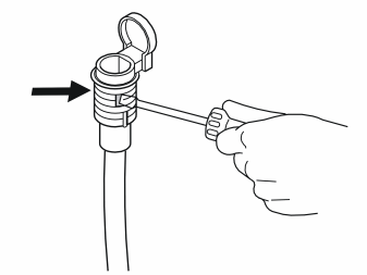
- Open the drainage holes on both sides of the connector. Use a screwdriver and press with manual force in the markings.
Installing the front engine block heater socket
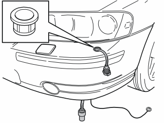
- Install the expander nut in the hole, with the guide pin in the guide hole.
- Route through the cable from the front socket, including the ground cable, from above and down. Let them hang down.
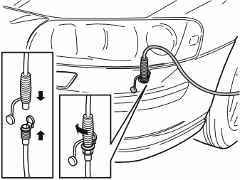
- Connect the cable to the front socket. Press down and turn the cable clockwise so that the expander nut expands.
- Align the cable from the front socket so that the hinge points to the headlamp. Remove the cable.
Applies to the XC90 up to and including model year -2006
Preparations
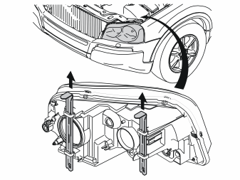
- Detach the left-hand headlamp by pulling up the two locking pins and then carefully pulling away the headlamp forwards.
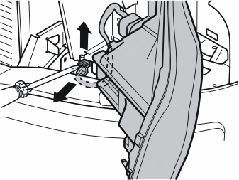
- Carefully prize up the catch on the connector for the headlamp with a screwdriver.
- Pull the catch up completely, detach the connector and place the headlamp to one side.
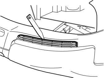
- Remove the left-hand grille from the bumper by carefully prizing it away with a weatherstrip tool.
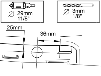
- Measure out for drilling the front socket hole as illustrated.
- Pre-drill the hole using a Ø3 mm (1/8") bit.
- Drill out the hole. Use a Ø29 mm (1 1/8") diameter hole saw.
- Remove any swarf.
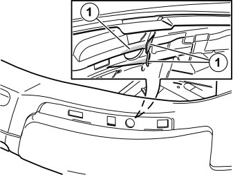
- Take a utility knife and cut out the discs (1) in such a way that they are equally as high. The plastic nut for the front socket then has a flat surface to be tightened against.
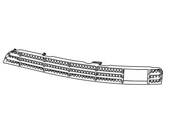
- Saw or cut out for the front socket connector in the second hole from the left in the left-hand grille of the bumper.
- Even off the edges.
- Press the grille into the bumper.
Installing the front engine block heater socket
Illustration A
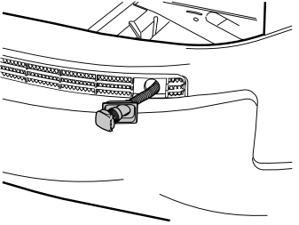
- Take the front intake, blind cover plug and plastic nut from the kit.
- Fit the blind cover plug on the front socket's connector and turn the connector so that the cover is opened to the left-hand side of the car as illustrated.
Illustration B
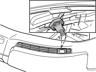
- Install the plastic nut.
- Tighten the plastic nut properly.
- Route the cable along the outside of the left-hand side member.
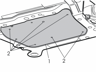
- Remove the engine splash guard (1) by first removing the screws (2).
Applies to the XC90 up to and including model year -2006, as well as the S60 and V70
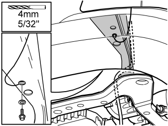
- Drill a hole in the front/lower edge of the side member with a Ø4 mm (5/32") bit.
- Apply anti-corrosion agent and secure the ground cable with the enclosed Ø4.8 mm (3/16") flanged screw and toothed washer (under the screw head).
Примечание: Connect the ground cable to the side member, not to the subframe.
- Secure the excess ground cable with a tie strap.
Applies to the XC90 from and including model year 2007-
Preparations
- Detach the left-hand headlamp by pulling up the two locking pins and then carefully pulling away the headlamp forwards.
- Carefully prize up the catch on the connector for the headlamp with a screwdriver.
- Pull the catch up completely, detach the connector and place the headlamp to one side.
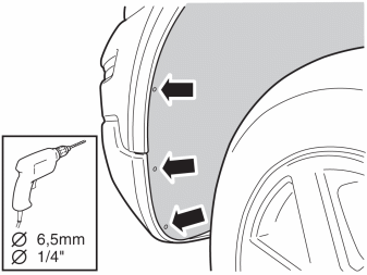
Step 22 applies to cars with fuel-driven parking heater installed
- Drill out the three rivets from the front edge of the left wing liner.
- Remove the remains of the rivets.
- Move the wing liner aside and fasten it so that the parking heater is accessible.
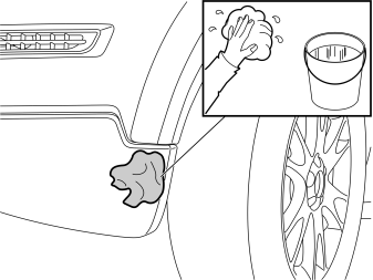
- Clean the bumper cover where the front engine block heater socket shall be secured.
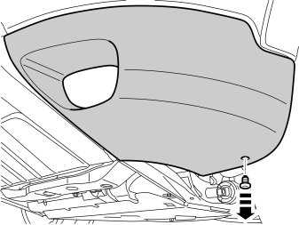
- Remove the clip on the panel for the front fog lamp.
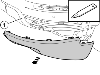
- Remove the panel over the fog lamp by carefully prising it loose from the bumper shell with a weatherstrip tool. The panel is held in place with catches. The corner (1) of the other panel section must be pryed loose since it overlaps the panel.
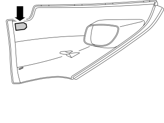
- Cut out according to the existing marking on the inside of the panel for the protective cover for the front engine block heater socket.
- Test and cut until the protective cover fits.
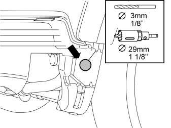
- Drill a Ø 29 mm (1 1/8 ") diameter hole using a hole saw according to the existing marking in the lower edge of the bumper cover. Pre-drill using a Ø 3mm (1/8 ") diameter drill bit.
Примечание: It is important that the hole is drilled right in the center of the marking in order to correspond with the hole cut out earlier.
- Even out the hole edges and remove the drill swarf.
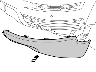
- Reinstall the front fog lamp panel.
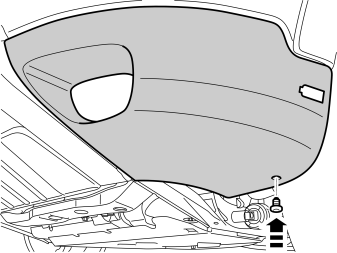
- Press the clip into the panel.
Installing the front engine block heater socket
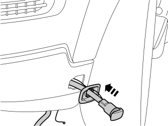
- Take the protective cover from the kit and press it into the hole cut in the bumper cover.
- Take the cable for the front engine block heater socket with ground lead from the kit and thread them through the protective cover.
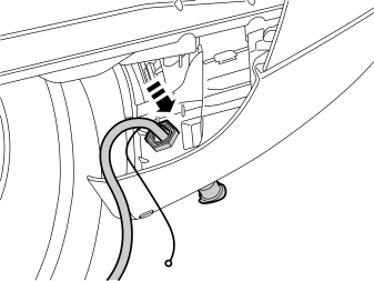
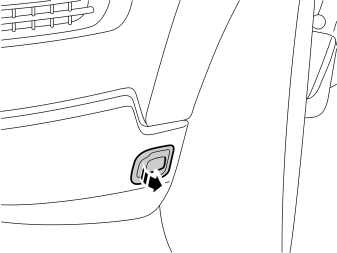
Illustrations A and B
- Install the nut from the kit.
- Rotate the connector for the front engine block heater socket so that the cover opens backwards (Illustration B).
- Tighten the front engine block heater socket to the bumper cover.
- Plug the electrical connector into the front engine block heater socket. Use the connector as a counterhold when tightening.
- Remove the cover on the radiator expansion tank.
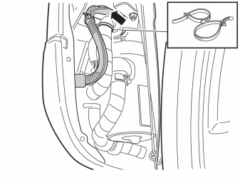
Step 32 applies to cars with fuel-driven parking heater installed
- Route the cable to the front intake with ground cable along the parking heater induction pipe. Secure them to the pipe with a double tie strap.
- Pull up the ground cable on the upper side of the plate where the connector to the fuel heater is located, and pull the thick cable underneath the plate.
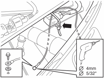
Step 33 applies to cars with fuel-driven parking heater installed
- Drill a hole in the front/top edge of the side member with a Ø4 mm (5/32") bit.
- Apply anti-corrosion agent to the edges of the holes and secure the ground cable with the enclosed Ø4.8 mm (3/16") flanged screw and toothed washer.
- Secure the excess length of ground cable with a tie strap from the kit. Clamp it at the gray connectors of the parking heater.
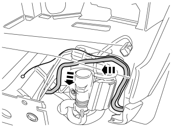
Step 34 applies to cars with fuel-driven parking heater installed
- Continue routing the thick cable on top of the fuel heater along the cables there. Then pull it under the plate where the connector for the fuel heater is, continuing underneath the side member, before the front mounting for the subframe.
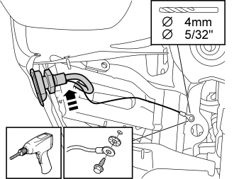
- Drill a hole in the front/lower edge of the side member with a Ø4 mm (5/32") bit.
- Apply anti-corrosion agent and secure the ground cable with the enclosed Ø4.8 mm (3/16") flanged screw and toothed washer.
Примечание: Connect the ground cable to the side member, not to the subframe.
- Secure the excess ground cable length with a tie strap from the kit.
Applies to all models
Applies to cars with gasoline engines
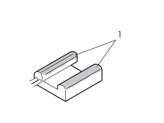
- Apply heat conducting paste (P/N 9499205), on the surfaces (1) of the heater body which are in contact with the cylinder block.
Applies to cars with gasoline engines
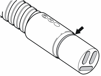
- Grease the O-ring on the connector for the heater's jointing cable with low temperature grease (part no. 1161417-9).
Примечание: Do not get any grease on the surfaces of the connector.
Applies to cars with stay for the turbocharger
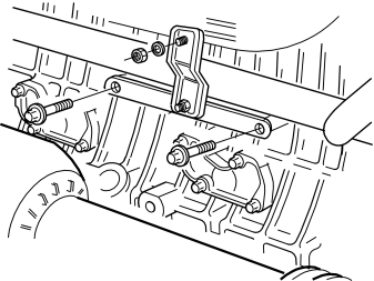
- Remove the stay.
Applies to cars up to and including model year -2004, with stay for the turbocharger,
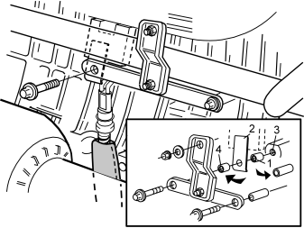
- Carefully clean the surface where the heater is to be located to provide good heat conduction to the cylinder block. Also clean the internal threads.
- Install the heater on the engine block as illustrated.
Подсказка: To facilitate the installation of the heater on the engine block, first secure the tensioner (2) by the heater using a small piece of butyl tape, and then also secure the spacer sleeves (1 and 4) on each side of the tensioner using small pieces of butyl tape.
- Install the spacer washer (1), (t =10 mm (25/64")), between the tensioner (2) and the mounting (3) in the engine block.
- Install the outer spacer washer (4), (t =32 mm (1 1/4")), between the stay and the tensioner (2).
- Tighten the heater using the screws from the kit. Tighten to 16 Nm (12 lbf.ft.).
- Take the radiation protection and cable from the kit. Thread the radiation protection onto the cable and connect the cable to the heater.
Applies to cars from model year 2005-, with stay for the turbocharger
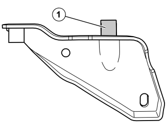
Illustration A
- Knock off the spacer (1) from the stay. Grind off the welds if the spacer is securely fastened.
Illustration B
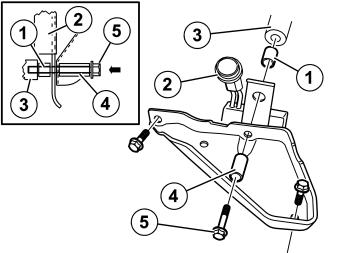
- Carefully clean the surface where the heater is to be located to provide good heat conduction to the cylinder block. Also clean the internal threads.
Подсказка: To facilitate the installation of the heater on the engine block, first secure the tensioner (2) by the heater using a small piece of butyl tape. Then also secure the spacer sleeve (1) on the rear side of the tensioner using a small piece of butyl tape.
Примечание: The bent section of the tensioner must point away from the heater.
- Install space washer (1)(t=10 mm (25/64")) between tensioner (2) and the mounting in the engine block (3). Install the outer spacer washer (4) (t=32 mm (1 1/4")) on the outside of the bracket.
- Thread through the long screw (5) so that everything is held together.
Illustration C
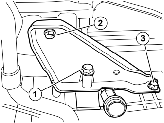
- Thread the heater and the tensioner. Install the turbocharger stay and screw using the three screws as follows:
- Tighten the screws to 16 Nm (12 lbf.ft.).
- Take the radiation protection and cable from the kit. Thread the radiation protection onto the cable and connect the cable to the heater
- Install the locking sleeve on the heater's connector.
Applies to cars without stay for the turbocharger
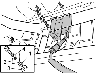
- Carefully clean the surface where the heater is to be located to provide good heat conduction to the cylinder block. Also clean the internal threads.
- Install the heater on the engine block as illustrated.
Подсказка: To facilitate the installation of the heater on the engine block, first secure the tensioner (2) by the heater using a small piece of butyl tape and then also secure the spacer sleeve (1) on the rear side of the tensioner using a small piece of butyl tape.
- Install space washer (1)(t=10 mm (25/64")) between tensioner (2) and the mounting in the engine block (3). Install the outer spacer washer (4) (t=32 mm (1 1/4")) on the outside of the tensioner (2).
- Tighten the heater using the screws from the kit. Tighten to 16 Nm (12 lbf.ft.).
- Take the radiation protection and cable from the kit. Thread the radiation protection onto the cable and connect the cable to the heater.
Applies to cars with gasoline engines
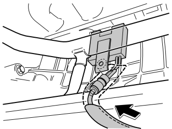
- Pull the radiation protection all the way up to the block heater, so that the joint and plastic casting is completely covered.
Примечание: It is important that the radiation protection covers the entire joint at the engine.
- Secure the radiation protection around the cable, to the block heater, using a gray, heat resistant tie strap at the lower edge of the radiation protection.
Only applies to TDI engines and immersion heaters
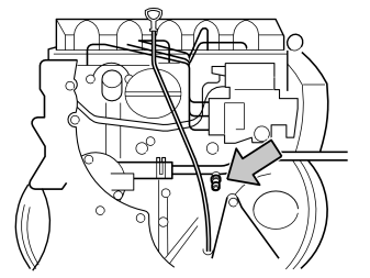
- Open the cap for the radiator's expansion tank.
- Position a collection container under the engine and open the coolant cock.
- Drain the coolant and close the cock.
Only applies to TDI engines and immersion heaters
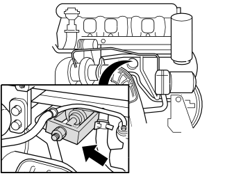
- Pull out the core plug using an extractor.
Only applies to TDI engines and immersion heaters
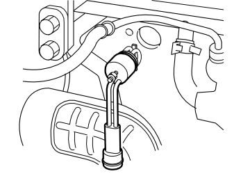
- Thread the O-ring onto the heater.
- Grease the O-ring using low temperature grease (P/N 1161427).
- Screw the immersion heater into the engine block. Tighten to 3.5 Nm (2.6 lbf.ft.).
- Clamp the cable at the pipe on the right-hand side of the reverse of the sub-frame. Use the tie strap from the kit.
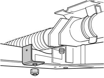
- Remove the existing nut from the steering gear.
- Install the bracket for mounting the branching connector and cables.
- Install the new supplied lock nut. Tighten to 48 Nm (36 lbf.ft.).
Applies if engine block heater and passenger compartment connector shall be fitted at the same time
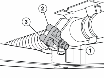
- Install the branching connector on the bracket with screw and nut from the kit.
- Grease the O-rings using low temperature grease (P/N 1161417-9).
- Connect the cables from the front socket (1), the passenger compartment socket (2) and the engine block heater (3) to the branching connector.
- Tighten the branching connector to the bracket for the steering gear.
Connection and finishing work, applies to all
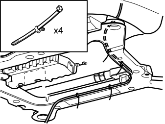
- Take four tie straps from the kit and press them into the holes on the inside of the subframe.
- Route the cable from the front socket above the front edge of the subframe and back to the cable from the engine block heater.
- Clamp the cable securely into the fitted tie straps.
- Grease the O-ring on the connector using low temperature grease (P/N 1161417-9).
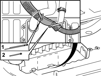
- Route the cable from the engine block heater over oil cooler and to the bracket previously installed.
- Take the double clamp (1) from the kit and secure the cable at the left-hand hose on the oil cooler. Secure the cable at the right-hand pipe using a tie strap (2) from the kit.
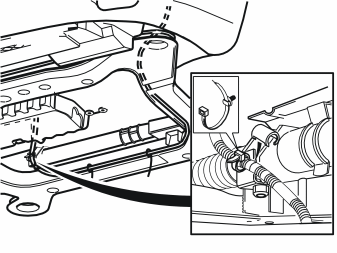
- Connect the cable from the front socket to the cable from the engine block heater, or to the branching connector.
- Press the locking sleeves (from the kit) over the cable splices.
- Take a clamp from the kit and press it into the hole on the previously installed bracket.
- Clamp the cable in at the bracket as illustrated.
Примечание: The cable must not be secured to the drive shaft, to the fuel lines, air conditioning (A/C) pipes or brake pipes. Ensure that the cable is not rubbing against any sharp edges and that it is not too close to the turbocharger (TC) or exhaust pipe to prevent damage from radiant heat.
Applies to the S60 and V70
- Reinstall the center air baffle and the engine splash guard. Torque tighten the engine splash guard screws to 25 Nm (19 lbf.ft.).
- Clamp the cable for the engine heater in the mounting on the left-hand side of the air baffle.
- Reinstall the air baffle on the right and left-hand sides.
Applies to the XC90
- Reinstall the engine splash guard. Torque tighten the engine splash guard screws to 25 Nm (19 lbf.ft.).
- Connect the headlamp and reinstall it.
Обсуждение и оценка
0Пока нет комментариев. Будьте первым.