Применимость
| Модель | Двигатель | Год |
|---|---|---|
| S60 (-09) | — | 2001–2009 |
Примечание: Certain parts in the kit illustrations are marked with A, B or C. Applicable to these:
Depending on how the car is equipped, different cable harnesses are required, or no cable harness at all. If the car has RTI preparation or satellite preparation but not RTI or satellite radio (Sirius), then neither cable harness A nor B is required.
A = Included in kit for cars not equipped with RTI, TV tuner or Sirius satellite radio.
B = Included in kit for cars which have RTI, TV tuner or Sirius satellite radio.
Applies to cars not equipped with RTI, TV tuner, Sirius or RTI/satellite preparation. For cars with one or several of these alternatives, go directly to step 40.
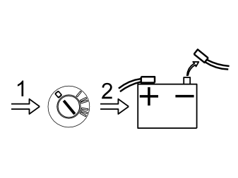
- Move the left-hand front seat to its rear position.
- Turn the ignition switch to position 0.
- On cars with manual gearbox. Remove the ignition key.
- Disconnect the battery negative lead.
Примечание: Wait at least five minutes before disconnecting the connectors or removing other electrical equipment.
Illustration A
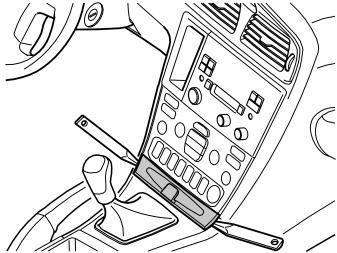
Applies to cars up to and including model year –2004 (CH –424999)
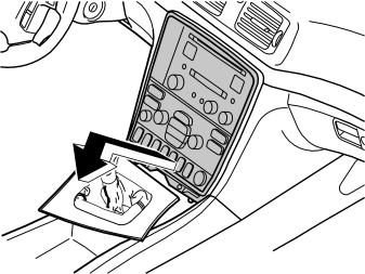
- Remove the panel in front of the gear selector lever. Pry off the panel using a plastic weatherstrip tool.
- Move the gear selector lever to the rear position.
Illustration B
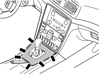
Applies to cars from model year 2005– (CH 425000–)
- Carefully prize away the gear selector lever cover panel together with the boot until the two clips release. Use a plastic weatherstrip tool. Pull the panel up until the four clips at the sides release.
Illustration A
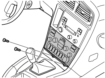
Applies to cars up to and including model year –2004 (CH –424999)
- Remove the two screws from the dashboard environment panel.
Illustration B
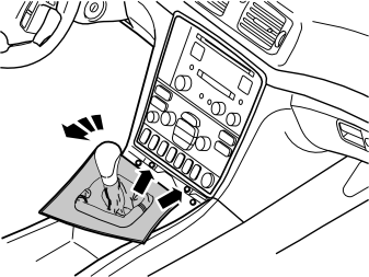
Applies to cars from model year 2005– (CH 425000–)
- Engage the handbrake and move the gear selector lever towards the rear.
- Rotate the panel to the left for better access.
- Remove the two screws holding the bracket with the radio and dashboard environment panel in the centre console.
Illustration A
Applies to cars up to and including model year –2004 (CH –424999)
- Angle the dashboard environment panel outwards so that it is possible to insert a couple of fingers between the centre console and the short side of the dashboard environment panel.
- Pull the dashboard environment panel downward maintaining the same angle and remove the dashboard environment panel. The panel is well secured, so some force is required to detach the panel. Unplug the connectors on the reverse side, and place the dashboard environment panel to one side.
Примечание: If any of the outer hooks break off, these must be repaired. The method for this can be found in the Workshop Manual in the section about the dashboard.
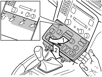
Illustration B
Applies to cars from model year 2005– (CH 425000–)
- Remove the bracket with dashboard environment panel and the radio from the centre console: Pull the lower edge out and downwards until it releases from the mounting at the upper edge. Then fold backwards.
Примечание: Do not damage the removed components or the surrounding panels. If necessary, the panel around the gear selector lever can be removed for additional space. The panel is secured with four catches on the underside along the boot.
- Unplug the connectors from the radio and dashboard environment panel, and from the telephone keypad if applicable. Place the unit to one side.
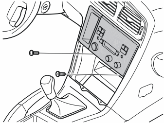
Applies to cars up to and including model year –2004 (CH –424999)
- Remove the screws from the bracket for the radio.
- Pull out the bracket with the radio. Pull the lower corner while pressing downwards.
- Unplug the connectors from the radio and the telephone keypad if applicable, and remove the bracket with the radio.
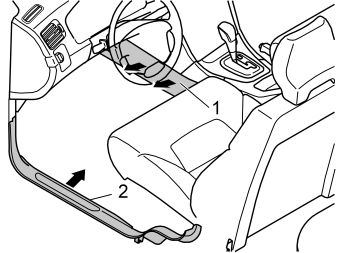
Applies to all models
- Remove the side panel (1) on the centre console. First twist the clip at the rear edge of the panel a 1/4 turn anticlockwise. Pull the rear edge of the panel outwards and backwards.
- Remove the sill trim panel (2).
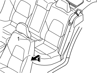
- Remove the seat cushion (1). First lift the front edge, pull it forwards and lift it out.
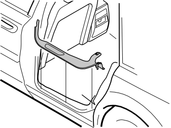
- Remove the sill moulding for the left-hand rear door.
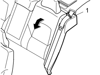
- Fold the left-hand rear backrest forward.
- Take the seat belt out from the guide (1).
- Repeat the operation on the other side.
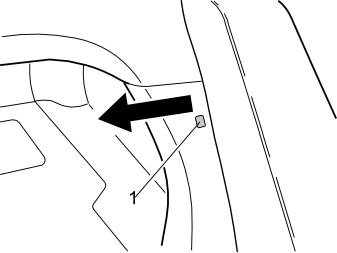
- Remove the clip (1) at the side of the left-hand side bolster.
- Pull the top edge of the left-hand front cargo compartment panel out to access the upper catch for the side bolster.
- Repeat the operation on the other side.
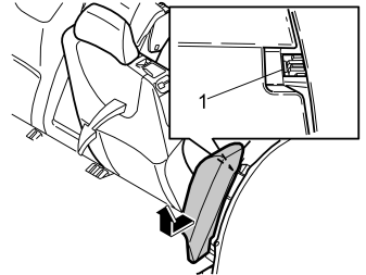
- Remove the left-hand side bolster. First press in the catch (1) at the top of the reverse of the side bolster, and pull it out slightly.
- Grasp the bolster using both hands. Twist anticlockwise until the catch on the inside releases.
- Remove the side bolster. First pull out the top of the side bolster. Then pull upwards.
- Repeat the operation on the other side.
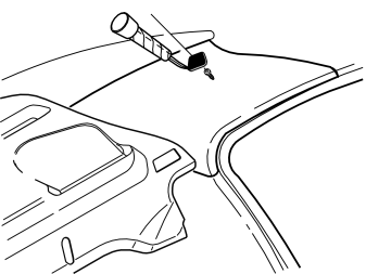
- Remove the cover and screw in the left-hand C-pillar panel.
- Repeat the operation on the other side.
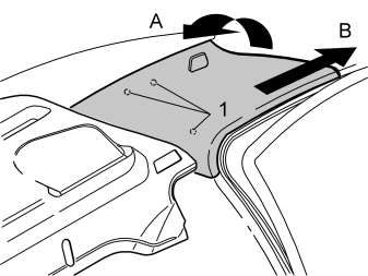
- Remove the rubber strip at the rear edge on the left-hand rear door frame
- Grasp the top edge of the C-post panel. Pull (A) the panel inwards until the three clips (1) release
- Then pull (B) the panel straight up. Place the panel to one side
- Repeat the operation on the other side.
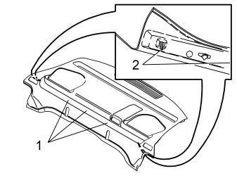
- Carefully lift the front edge of the parcel shelf until the clips (1) release.
- Raise the panel more until the guide pins (2) disengage from their holes.
- Pull out the parcel shelf and lay it on the folded backrests.
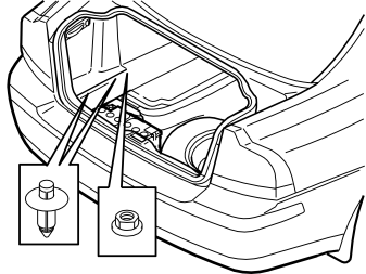
- Lift out the cargo compartment carpet.
- Press in the centre of the clips on the lower edge of the folding side panel on the left-hand side until a click is heard.
- Remove the two clips.
- Remove the plastic nut at the front/lower edge of the side panel.
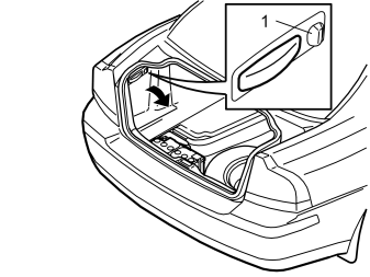
- Turn the knob (1) on the left-hand side through 90°.
- Fold the side panel inwards and remove it.
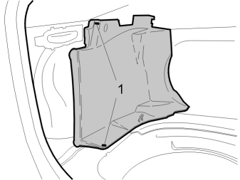
- Remove the clips (1) and plastic nut from the left front side panel in the cargo compartment.
- Remove the front side panel.
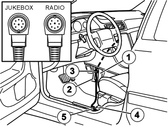
- Take the DIN cable from the kit, lift up the floor carpet and route it underneath, up between the front air duct (1) and the strut (2) for the centre console.
Примечание: Make sure that it is the connector with a guide pin which points upward (see illustration), which is routed to the radio socket.
- Route the cable through the compartment for the radio.
- Clamp the cable in the strut (3), using the clamp from the kit.
- Route the cable on above and alongside the front air duct to the member (4) for the seat mounting.
- Clamp the cable at the existing cable harness (5).
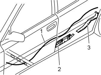
- Route the cable (1) under the carpet, along the left-hand side of the car to the rear door.
- Route the cable further under and along the front cable duct (2). Continue along the right-hand side of the rear cable duct (3).
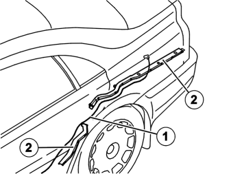
- Route the DIN cable (1) along the two cable ducts/cable harness (2) under the insulation panel and out through the hole in the body to the cargo compartment.
- Route the DIN cable under the four connectors in the front cable duct.
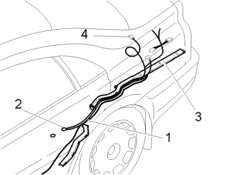
Applies to cars up to and including model year –2004 (CH –424999)
- Take the cable harness for power supply (1) from the kit. Connect the ground lead to the rear ground terminal (2) under the seat cushion. Tighten to 10 Nm (7 lbf.ft.).
- Route the ground lead under the four connectors in the front cable duct.
- Route the power supply cables (1) along the rear cable duct (3) under the insulation panel and out through the hole in the body to the cargo compartment. Position the cable end with the two red/white (R/W) single cables and the two green connectors at the rear fuse holder. Route the long cable with the green connector (4) to the pre-routed DIN cable's connector.
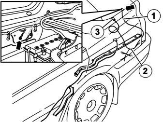
Applies to cars from model year 2005– (CH 425000–)
- Take the cable (1) for power supply from the kit. Connect the ground lead to the existing ground terminal behind the battery. Tighten the screw. Tighten to 10 Nm (7 lbf.ft.). Position the cable end with the two red/white (R/W) single cables and the two green connectors (2) by the rear fuse holder.
- Route the cable harness on the left-hand side of the cable duct. Route the long cable with the green connector (3) to the pre-routed DIN cable's connector.
-
Подсказка: > Two people should assist with drilling the holes and installing the Jukebox and console.
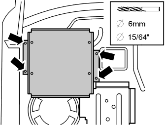
Take the Jukebox console from the kit and position it against the panel under the parcel shelf on the left-hand side as illustrated, hold it still and mark out the rear hole in the right-hand side of the console.
Примечание: Do not damage the cables while drilling.
Use protective safety goggles if lying in the cargo compartment to drill.
- Drill the hole using a Ø 6 mm (15/64”) diameter drill bit, and deburr it.
- Take four M5 screws, washers and nuts from the kit. Install the console with one screw in the drilled hole. Tighten the screw by hand.
- Align the console so that it is straight.
- Mark out the three remaining holes. Remove the console.
- Drill the three remaining holes, deburr them and apply anti-corrosion protection to the edges of the holes.
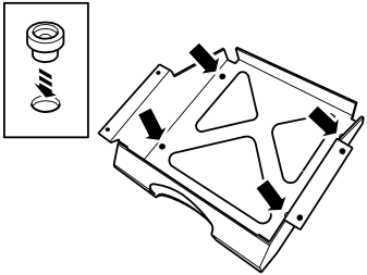
- Take the console and spacer washers from the kit and press the washers into the holes in the bottom of the console.
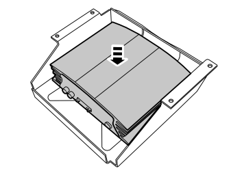
- Take the Jukebox with the blind rivets and plastic washers from the kit, position it over the spacer washers installed in the console.
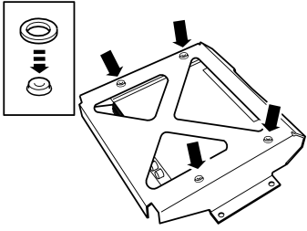
- Turn the whole unit upside-down and place a soft separator panel on the top of the Jukebox, so that it is pressed against the bottom of the console.
- Take the four plastic washers and position them over the spacer washers previously installed.
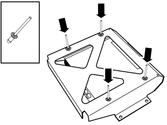
- Take the four blind rivets and rivet the Jukebox into the console.
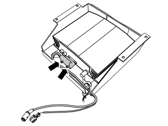
- Take the adapter cable from the kit and connect in the corresponding socket in the rear edge of the Jukebox.
- Tighten the connector screws.
- Position the cables on the inside of the rear of the console.
- Take a tie strap from the kit and clamp in the cable at one corner of the console as illustrated.
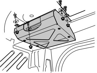
- Install the console and the Jukebox with four screws, washers and nuts to the underside of the parcel shelf and tighten.
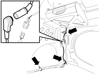
- Connect the DIN cable and the long cable with the green connector in the pre-routed cable harness to the Jukebox adapter cable.
- Clamp the cables in the body and at the existing cable harnesses with tie straps from the kit. Make sure that the cables do not chafe against sharp edges in the body.
Connecting to the fuse holder
Applies to cars up to and including model year –2004 (CH -424999)
Illustration A
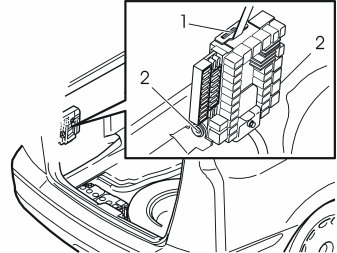
- Remove the rear electronic module (REM) by opening the catch (1) on the top of the module. Tip the module forward and lift it out of the mountings (2).
Illustration B
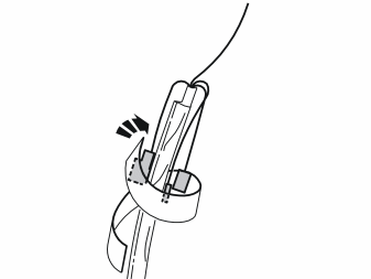
- Position both the green connectors and the red/white (R/W) single cable with the smaller cable terminal facing backwards along the cable. Insulate the cables. Secure the cables using the foam tape from the kit. They must not come into contact with the chassis. Single cable with the larger cable terminal should be loose.
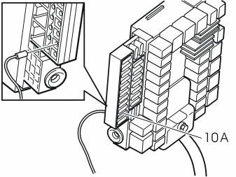
- Connect the red/white (R/W) single cable with the larger cable terminal to fuse socket 10 on the fuse holder.
- Install a 10A fuse in fuse holder 10.
- Reinstall the electronic module.
Applies to cars from model year 2005– (CH 425000–)
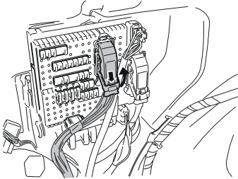
- Press in the catch on the rear brown connector in the cargo compartment fuse holder. Turn up the lock arm as far as possible and pull out the connector.
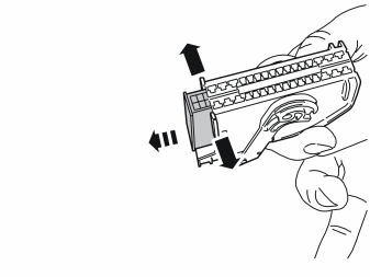
- Carefully prise apart the sides of the connector holder in the ends so that the connector can pass by the retaining hooks.
- Pull out the connector.
- Position both the green connectors and the red/white (R/W) single cable with the larger cable terminal facing backwards along the cable. Insulate the cables. Secure the cables using the foam tape from the kit. They must not come into contact with the chassis. The single cable with the smaller cable terminal should be loose.
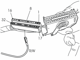
- Connect the red/white (R/W) single cable with the smaller cable terminal to position 8 in the connector.
- Reinstall the connector in the holder and reinstall the whole unit in the fuse holder.
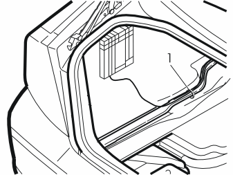
Applies to all models
- Clamp the cables in at the cable harness/cable duct on the left-hand side with a tie strap from the kit. Clamp in any excess cable neatly.
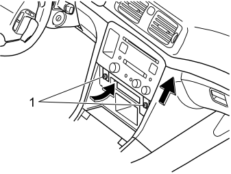
Applies to cars up to and including model year –2004 (CH –424999)
- Take the radio to the radio compartment and connect the Digital Jukebox DIN cable and other connectors to the radio.
- Plug in the connectors for the phone keypad, if applicable.
- Reinstall the bracket with the radio. Tighten the bracket and radio using the screws (1).
- Connect the connectors to the dashboard environment panel. Reinstall the dashboard environment panel.
- Reinstall the panel in front of the gear selector lever.
Applies to cars from model year 2005– (CH 425000–)
- Plug in the Digital Jukebox connector, and other connectors to the radio.
- Plug in the connectors for the dashboard environment panel.
- Plug in the connectors for the phone keypad, if applicable.
- Reinstall the unit with radio and dashboard environment panel in the centre console. Tighten with the two screws.
- Reinstall the panel around the gear selector lever
Applies to all models
- Fold back the carpet by the front seat.
- Refit the centre console's side panel and the sill trim panels in the left front and rear doors.
- Reinstall the parcel shelf panel.
- Reinstall the C-post panels.
- Reinstall the front and the folding rear panel in the left-hand side of the cargo compartment.
- Reinstall the side cushions.
- Fold the backrests back into place.
- Reinstall the seat cushion.
- Turn the ignition key to position II.
- Reconnect the battery negative lead.
- Reinstall the cargo compartment carpet.
Check that the system is working.
- Install the memory unit (DMS) in the Jukebox.
- Switch on the radio and select the 10-CD changer.
Примечание: The first time the system is started it takes approx. 30 seconds before it is operational.
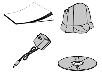
- Check that the parts shown in the illustration are in the storage compartment supplied with the Jukebox, and that this is positioned as illustrated:
Applies to cars which are equipped with RTI, TV tuner, Sirius or RTI/satellite preparation
- Turn the ignition switch to position 0.
- On cars with manual gearbox: Remove the ignition key.
- Disconnect the battery negative lead.
Примечание: Wait at least five minutes before disconnecting the connectors or removing other electrical equipment.
- Remove the seat cushion (1). First lift the front edge, pull it forwards and lift it out.
- Fold the left-hand rear backrest forward.
- Take the seat belt out from the guide (1).
- Repeat the operation on the other side.
- Remove the clip (1) at the side of the left-hand side bolster.
- Pull the top edge of the left-hand front cargo compartment panel out to access the upper catch for the side bolster.
- Repeat the operation on the other side.
- Remove the left-hand side bolster. First press in the catch (1) at the top of the reverse of the side bolster, and pull it out slightly.
- Grasp the bolster using both hands. Twist anticlockwise until the catch on the inside releases.
- Remove the side bolster. First pull out the top of the side bolster. Then pull upwards.
- Repeat the operation on the other side.
- Remove the cover and screw in the left-hand C-pillar panel.
- Repeat the operation on the other side.
- Remove the rubber strip at the rear edge on the left-hand rear door frame
- Grasp the top edge of the C-post panel. Pull (A) the panel inwards until the three clips (1) release
- Then pull (B) the panel straight up. Place the panel to one side
- Repeat the operation on the other side.
- Carefully lift the front edge of the parcel shelf until the clips (1) release.
- Raise the panel more until the guide pins (2) disengage from their holes.
- Pull out the parcel shelf and lay it on the folded backrests.
- Lift out the cargo compartment carpet.
- Press in the centre of the clips on the lower edge of the folding side panel on the left-hand side until a click is heard.
- Remove the two clips.
- Remove the plastic nut at the front/lower edge of the side panel.
- Turn the knob (1) on the left-hand side through 90°.
- Fold the side panel inwards and remove it.
- Remove the clips (1) and plastic nut from the left front side panel in the cargo compartment.
- Remove the front side panel.
Applies to cars up to and including model year –2004 (CH –424999)
- Take the cable harness for power supply (1) from the kit. Connect the ground lead to the rear ground terminal (2) under the seat cushion. Tighten to 10 Nm (7 lbf.ft.).
- Route the ground lead under the four connectors in the front cable duct.
- Route the power supply cables (1) along the rear cable duct (3) under the insulation panel and out through the hole in the body to the cargo compartment. Position the cable end with the two red/white (R/W) single cables and the two green connectors by the RTI/DVD unit. The long cable with the green connector (4) is routed to the underside of the parcel shelf later on.
Applies to cars from model year 2005– (CH 425000–)
- Take the cable (1) for power supply from the kit. Connect the ground lead to the existing ground terminal behind the battery. Tighten to 10 Nm (7 lbf.ft.).
- Position the cable end with the two red/white (R/W) single cables and the two green connectors (2) by the RTI/DVD unit.
- Route the cable harness on the left-hand side of the cable duct. The long cable with the green connector (3) is routed to the underside of the parcel shelf later on.
-
Подсказка: > Two people should assist with drilling the holes and installing the Jukebox and console.
Take the Jukebox console from the kit and position it against the panel under the parcel shelf on the left-hand side as illustrated, hold it still and mark out the rear hole in the right-hand side of the console.
Примечание: Do not damage the cables while drilling.
Use protective safety goggles if lying in the cargo compartment to drill.
- Drill the hole using a Ø 6 mm (15/64”) diameter drill bit, and deburr it.
- Take four M5 screws, washers and nuts from the kit. Install the console with one screw in the drilled hole. Tighten the screw by hand.
- Align the console so that it is straight.
- Mark out the three remaining holes.
- Remove the bracket.
- Drill the three remaining holes, deburr them and apply anti-corrosion protection to the edges of the holes.
- Take the console and spacer washers from the kit and press the washers into the holes in the bottom of the console.
- Take the Jukebox with the blind rivets and plastic washers from the kit and position it over the spacer washers installed in the console.
- Turn the whole unit upside-down and place a soft separator panel on the top of the Jukebox, so that it is pressed against the bottom of the console.
- Take the four plastic washers and position them over the spacer washers previously installed.
- Take the four blind rivets and rivet the Jukebox into the console.
- Take the adapter cable from the kit and connect in the corresponding socket in the rear edge of the Jukebox.
- Tighten the connector screws.
- Position the cables on the inside of the rear of the console.
- Take a tie strap from the kit and clamp in the cable at one corner of the console as illustrated.
- Install the console and the Jukebox with four screws, washers and nuts to the underside of the parcel shelf and tighten.
- Connect the short DIN cable from the kit and the long cable with the green connector in the pre-routed cable harness to the Jukebox adapter cable.
- Clamp the cables in the body and at the existing cable harnesses with tie straps from the kit. Make sure that the cables do not chafe against sharp edges in the body.
Connecting to the DVD unit
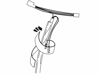
- Position the single cables in the routed cable harness backwards along the cable. Insulate and secure them by the cable with foam tape from the kit. The two green connectors must be loose.
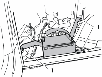
- Unscrew the screws (1) and remove the DVD drive with the console from the side of the body.
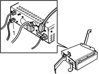
- Unplug the power supply connector (1) to the DVD unit.
Illustration A
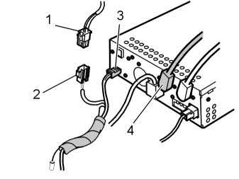
- Plug in the connector (1) previously detached from the DVD unit to one connector (2) in the cable harness to the Jukebox power supply.
- Plug in the other connector (3) for the Jukebox power supply to the DVD unit.
- Connect the DIN cable (4) from the Jukebox. (For cars with TV or Sirius unit, the DIN cable must be connected to this instead. Illustration B).
- Reinstall the DVD drive and tighten the screws to 10 Nm (7.5 lbf.ft.).
Applies to cars -2004
- Replace the fuse in fuse holder 10 in the rear electronic module (REM) with a 10 A fuse.
Illustration B
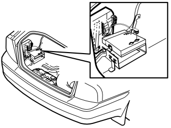
- Clamp the cables in at the cable harness/cable duct with a tie strap from the kit.
- Clamp any cable excess.
- Reinstall the parcel shelf panel.
- Reinstall the C-post panels.
- Reinstall the front and the folding rear panel in the left-hand side of the cargo compartment.
- Reinstall the side bolster.
- Fold the backrests back into place.
- Reinstall the seat cushion.
- Turn the ignition key to position II.
- Reconnect the battery negative lead.
- Reinstall the cargo compartment carpet.
Check that the system is working.
- Install the memory unit (DMS) in the Jukebox.
- Switch on the radio and select the 10-CD changer.
Примечание: The first time the system is started it takes approx. 30 seconds before it is operational.
- Check that the parts shown in the illustration are in the storage compartment supplied with the Jukebox, and that this is positioned as illustrated:
Обсуждение и оценка
0Пока нет комментариев. Будьте первым.