Применимость
| Модель | Двигатель | Год |
|---|---|---|
| 940 | — | 1991, 1992 |
Специальные инструменты
- 🔧 ПРОВЕРОЧНОЕ УСТРОЙСТВО (SRS)
- 🔧 МУЛЬТИМЕТР (ЦИФРОВОЙ)
Внимание: Under no circumstance may an ohmmeter or other current-generating
device be used to test the resistance of the inflator module or harness conductivity
when the inflator module is connected.
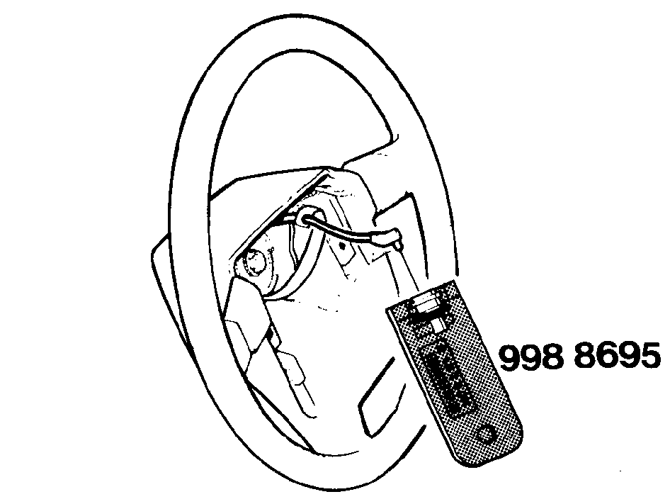
Use of test resistor
Connect rest resistor. Attempt to clear fault codes - recheck
whether codes are still displayed.
- If fault code 4 or 5 is displayed when vehicle arrives at workshop, erase fault code after installing resistor. If fault code 4 or 5 does not reappear when resistor is connected although no repair or replacement work has been carried out, bag assembly must be replaced.
- If fault code remains displayed after resistor has been connected, wiring, contact reel or crash sensor is faulty. See B7 Connect test resistor 998 8695 in place of bag assembly.
- If fault code 4 or 5 is displayed, the test resistor may have 'operated'.
Check resistance across terminals. Correct value is 1.8-2.5 ohms. Resistor
is useless if it has "operated". Check wiring or replace crash sensor. Order
new test resistor.
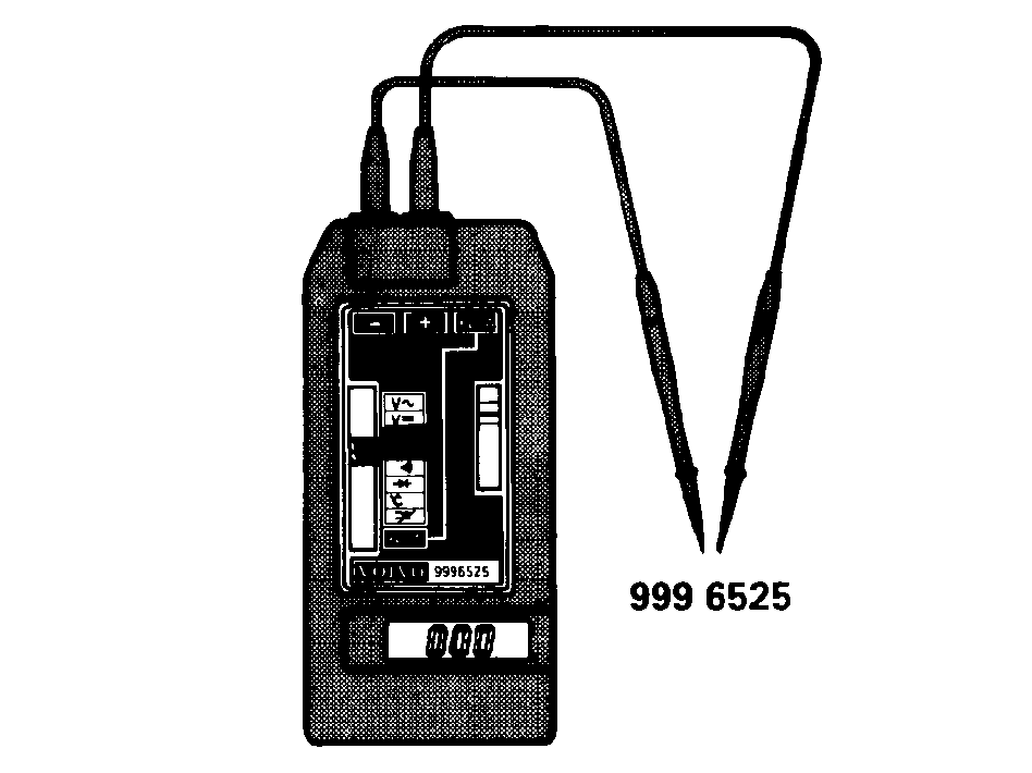
Внимание: Bag assembly deployment could occur as a result of using a
current-carrying device to diagnose the SRS system.The inflator must be disconnected before using an ohmmeter
to test components.Never use an ohmmeter to measure the resistance of the bag assembly.
Внимание: Do not deviate from the methods and procedures contained in
this manual.
Внимание: Never use an ohmmeter to test the inflator. Inflator
faults are indicated by 4 or 5 fault code flashes which require that the wiring
and related components be checked, never the inflator itself.
Примечание: An ohmmeter may be used to check the resistance of special tool 🔧 ПРОВЕРОЧНОЕ УСТРОЙСТВО (SRS).
Test resistor 998 8695
A simple aid has been developed to facilitate fault tracing and to enable
the SRS system to be checked before the bag assembly is installed following
fault tracing or repair. The resistor has the same resistance as the bag assembly
and is provided with an identical connector.
The resistor has three applications:
-
- Checking the system on completion of work. Since the resistor and bag assembly possess the same resistance, the resistor can be operated" by the same current which would normally deploy the assembly. All fault codes should be read and corrected on completion of fault tracing or repair work prior to installing the bag assembly.
-
- Checking the crash sensor and wiring between the sensor and bag assembly. See description below.
-
- Establishing that bag assembly is faulty by eliminating other causes. See description below.
Type of ohmmeter
The ohmmeter shall have the following ranges and accuracy:2000 ohm ±1%200 kohm ±1%Volvo digital multimeter 🔧 МУЛЬТИМЕТР (ЦИФРОВОЙ)
is recommended.
Switch off ignition
Disconnect battery ground lead.
Remove bag assembly
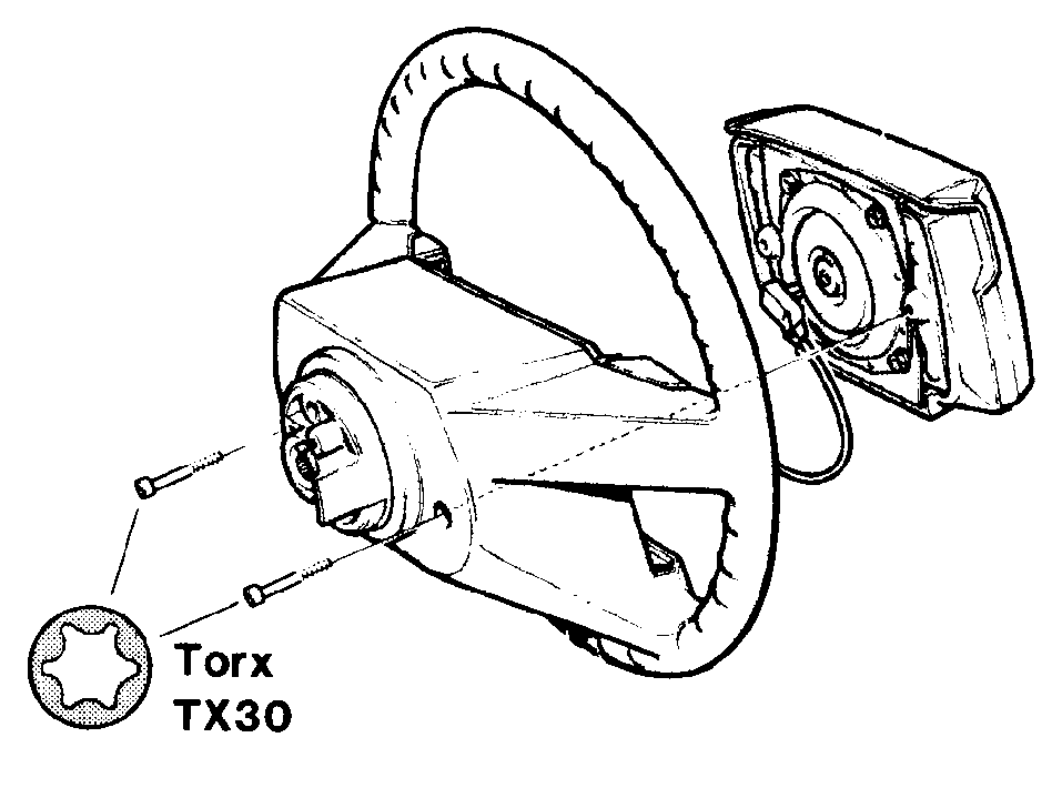
Remove bag assembly by undoing the two Torx bolts at the
rear. Open connector and lift out bag assembly.
Unbolt driver's seat and tilt backwards
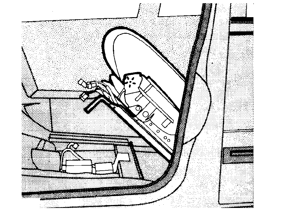
Remove bolts securing slide rails to floor. Open seat wiring
connectors. Tilt seat backwards. Lift carpet and remove heating duct.
Remove knee bolster and reinforcing panel
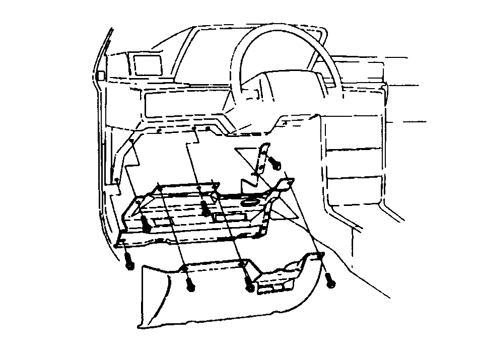
Fold back carpet to expose connectors.
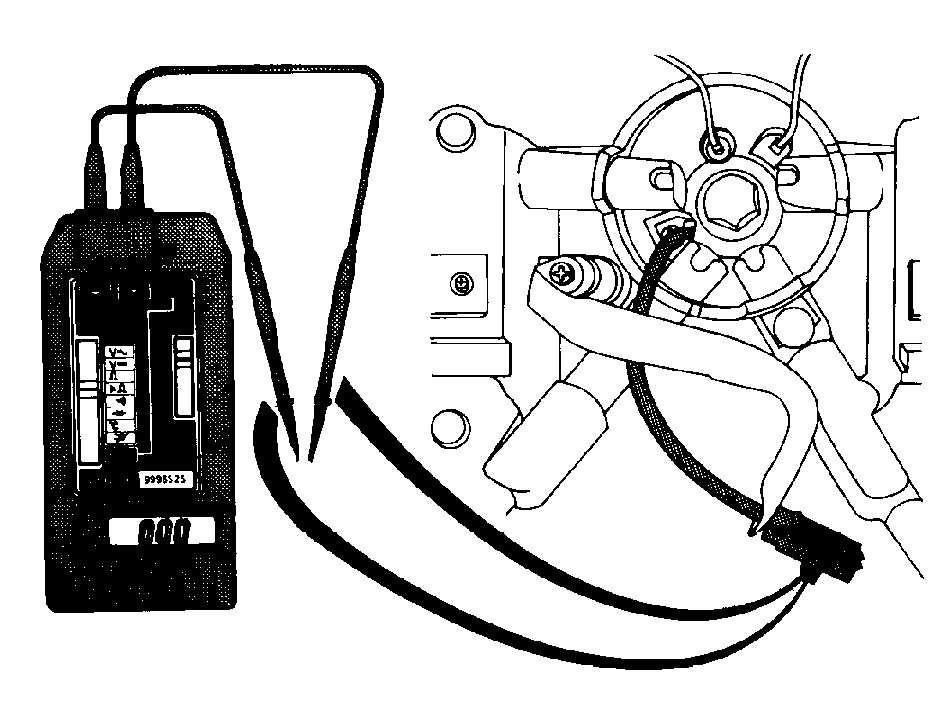
1. Checking at contact reel connector
(Also see wiring diagram Checking wiring harnesses )Procedure is designed to check wiring between bag assembly and crash
sensor, including certain crash sensor components.
Осторожно: Extreme care is required to avoid damaging connector!
Insert two small steel pins (such as needles) with max. diameter of
1 mm (.04 in) in bag assembly connector.Connect ohmmeter to pins and read resistance.Warning !
Осторожно: Never use an ohmmeter to test the bag assembly.
In the case of a bag assembly fault, as indicated by code 4 or 5, the wiring
and associated components - never the bag assembly itself-
must be checked.
Sensors with ground wire (black) connected:
| To mounting | 200 ohm |
|---|---|
| All others | 2000 ohm |
Reading of zero indicates short-circuit. Ensure that orange connector
is securely joined and that wiring is not damaged (pinched).Reading of infinity indicates open circuit in wiring or contact reel.
Check as described in 2 below.
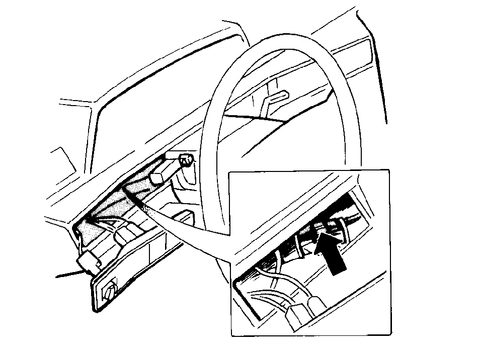
2. Checking at upper connector of wiring harness
(See also wiring diagram Checking wiring harnesses )If, unlike previous check, measurement gives correct value, contact
reel is damaged and must be replaced.Undo orange connector at steering column and measure resistance between
connector and crash sensor.
Sensors with ground wire (black) connected:
| To mounting | 200 ohm |
|---|---|
| All others | 2000 ohm |
If reading is incorrect in this case also, check at connector at centre
console as described in 3. below.
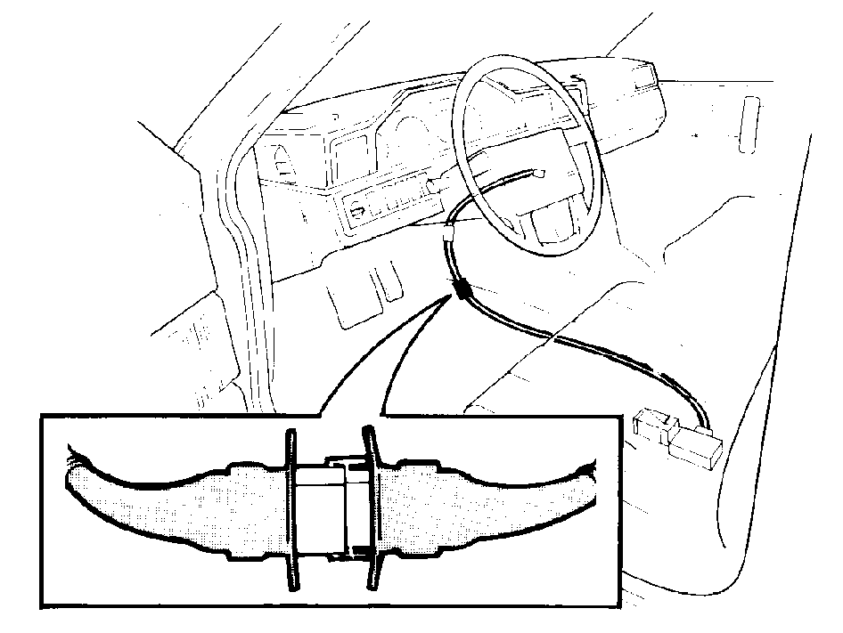
3. Checking at connector at centre console
(See also wiring diagram Checking wiring harnesses )
Sensors with ground wire (black) connected:
| To mounting | 200 ohm |
|---|---|
| All others | 2000 ohm |
- If reading is correct, replace wiring between connector and contact reel.
- If reading is incorrect, replace crash sensor.
Внимание: Under no circumstances may an ohmmeter or other current-generating
device be used to test the resistance of the inflator module or harness continuity
when the inflator module is connected.
Примечание: An ohmmeter may be used to check the resistance of special tool 🔧 ПРОВЕРОЧНОЕ УСТРОЙСТВО (SRS).
Correct readings: Sensors with ground wire (black) connected:
| To mounting | 200 ohm |
|---|---|
| All others | 2000 ohm |
Always measure downwards "towards" the sensor.
Внимание: Bag assembly deployment could occur as a result of using a
current-carrying device to diagnose the SRS system.The inflator must be disconnected before using an ohmmeter
to test components.
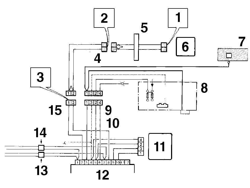
-
- Contact reel connector
-
- Wiring harness upper connector
-
- Connector at centre console
-
- Orange connector
-
- Contact reel
-
- Bag assembly
-
- Warning lamp
-
- Central electrical unit, relays
-
- Yellow connector
-
- Two types of ground connection are used
-
- Standby power unit
-
- Crash sensor
-
- Belt tensioner, left. Dark green connector
-
- Belt tensioner, right. Dark green connector
-
- Orange connector
Осторожно: When carrying out resistance measurements:
Always measure downwards "towards" crash sensor
Switch off ignition
Disconnect battery ground lead
Checking other SRS wiring
Check that all connectors are
securely joined, and that no wiring is pinched or otherwise damaged.
Resistance measurement should not be carried out. Check by inspecting
and feeling wiring.
Connect test resistor 998 8695 in place of bag assembly
Внимание: Never use an ohmmeter to test the bag assembly.
In the case of a bag assembly fault, as indicated by code 4 or 5, the wiring
and associated components - never the bag assembly itself-
must be checked.
Turn ignition switch to position II (ignition on)
Connect
battery ground lead.
Clearing fault code
760, 1987/All 740s
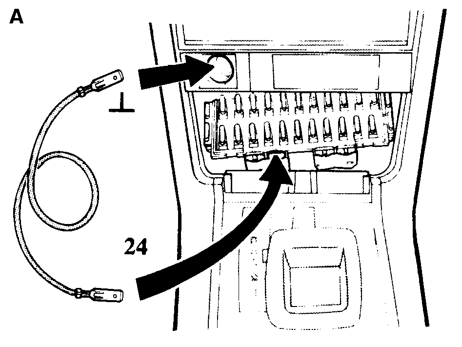
-
- Terminal 24, left side.Use 200 mm (8 in) lead.
780
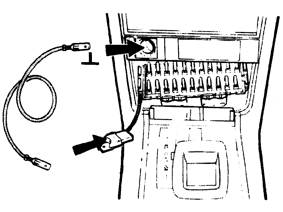
-
- Fuse holder or connector.Use 200 mm (8 in) lead.
When fault has been corrected, warning lamp must be cancelled (fault
code cleared) to restore normal operation.Procedure is as follows:Repeat code display procedure (by grounding test terminal for 2-5 seconds).Ground test terminal three times within 1.5 to 5 seconds, for at least
0.25 seconds on each occasion.
Примечание: Ground lead must be fitted with spade connectors at both ends.
Grounding action must be firm and must not be too brief.
Do not switch off ignition between request and clearance
of fault code.Warning lamp will be extinguished for 4 seconds and relit for 3 seconds
to confirm clearance of fault codes. Final extinction of lamp indicates restoration
of normal function.
If lamp does not go out
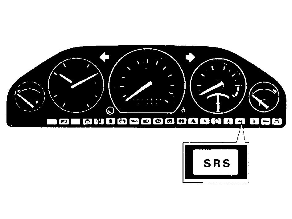
Uncorrected fault is still present. Repeat display procedure
and correct fault. If fault codes 4 or 5 are displayed, install new bag assembly
and repeat clearance procedure.
Switch off ignition and disconnect battery ground lead
Remove test resistor 998 8695
Install reinforcing panel and soundproofing
Tightening torques:M6 bolt: 8 Nm (5.8 ft lb)M8 bolt: 20 Nm (15 ft lb)
Install:
- air duct
- carpet
- seat; tighten floor mounting bolts to 48 Nm (35 ft lb)
Install bag assembly
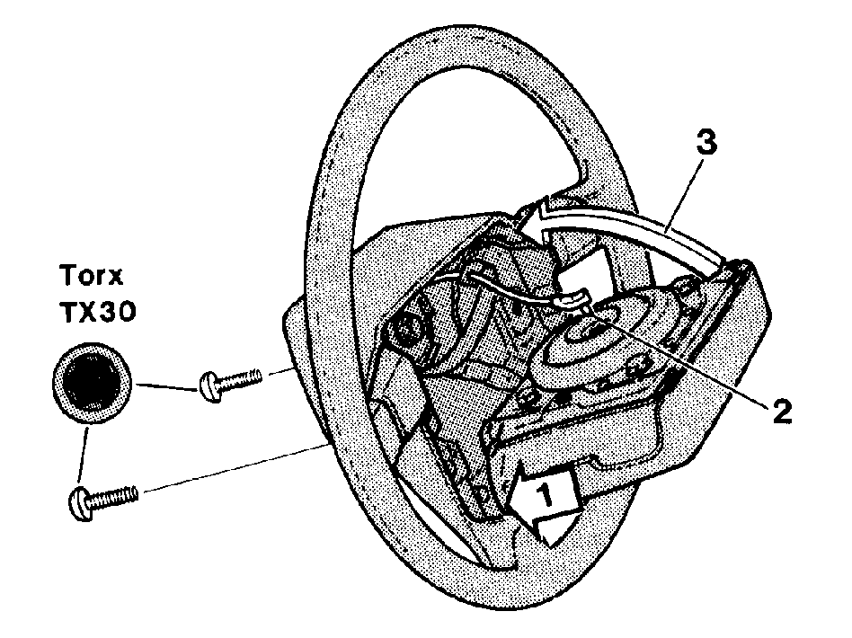
Rest bottom of assembly on steering wheel (1) and rejoin
connector (2). Seat assembly in position and retighten Torx bolts from rear
(3). Tightening torque: 8 Nm (5.8 ft lb).Ensure that lead is clear and is not pinched.
Примечание: Tighten right-hand screw first.
Double-check that bag assembly is mounted securely
Turn ignition key to position II (ignition off) and reconnect battery
ground lead
Check that SRS warning lamp is extinguished
If not, fault
is still present in system. Display fault codes, repair and reclear codes.