Применимость
| Модель | Двигатель | Год |
|---|---|---|
| S60 (-09) | — | 2001–2009 |
Примечание: - Points 1-32 apply to cars without RTI
- Points 33-50 apply to cars with RTI.
Points 1-32 apply to cars without RTI Interior preparations
- Move the left front seat to its rearmost position.
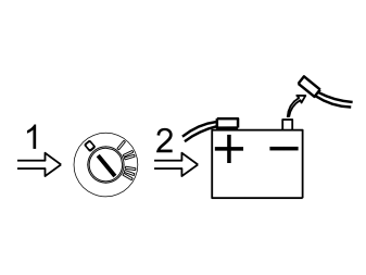
- Turn the ignition key to position 0
- Cars with manual gearboxes: Remove the ignition key
- Disconnect the battery negative lead.
Примечание: Wait at least five minutes before disconnecting the connectors or removing other electrical equipment.
Illustration A applies to cars up to and including -2004 (CH -424999)
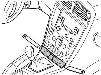
- Remove the panel in front of the gear selector lever. Pry off the panel using a plastic weatherstrip tool
- Move the gear selector lever to the rearmost position.
Illustration B applies to cars from model year 2005- (CH 425000-)
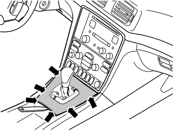
- Detach the rear edge of the gear selector lever cover together with the boot until the two clips release. Use a plastic weatherstrip tool. Pull the panel up until the four clips at the sides release.
Illustration A applies to cars up to and including -2004 (CH -424999)
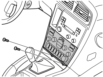
- Remove the two screws from the dashboard environment panel.
Illustration B applies to cars from model year 2005- (CH 425000-)
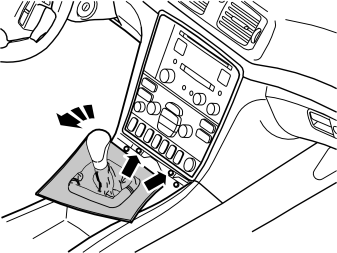
- Apply the handbrake. Move the gear selector backwards
- Turn the panel to the left to facilitate access
- Remove the two screws holding the bracket with the radio and the dashboard environment panel in the centre console.
Illustration A applies to cars up to and including -2004 (CH -424999)
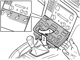
- Angle the dashboard environment panel outwards so that it is possible to insert a couple of fingers between the centre console and the side of the dashboard environment panel
- Detach the dashboard environment panel by pulling it downwards while maintaining the same angle. Some force is required because the panel is tightly installed. Disconnect the connectors on the reverse of the dashboard environment panel. Place the dashboard environment panel to one side.
Примечание: If any of the outer hooks break off, these must be repaired. The method for this can be found in the Workshop Manual in the section about the dashboard.
Illustration B applies to cars from model year 2005- (CH 425000-)
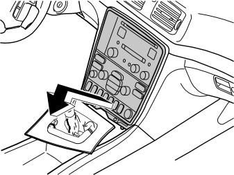
- Remove the bracket with dashboard environment panel from the centre console: Pull the lower edge out and downwards until it releases from the mounting at the upper edge. Then fold backwards.
Примечание: Do not damage the removed components and surrounding panels.
If necessary, remove the panel around the gear selector lever to gain more space. The panel is secured by four catches on the under side at the boot
- Disconnect the connectors from the radio and dashboard environment panel. Also disconnect the connector from the phone keypad if applicable. Place the unit to one side.
Applies to cars up to and including model year -2004 (CH -424999)
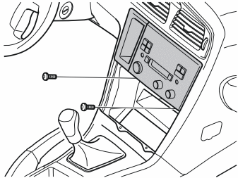
- Remove the screws from the bracket for the radio
- Pull out the bracket with the radio. Pull the lower corner while pressing downwards
- Disconnect the connectors from the radio. Remove the bracket and radio.
Applies to all models
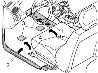
Remove:
- the left-hand side panel (1) from the centre console. First turn the screw clip. Pull the panel outwards and backwards
- the sill trim panel (2) at the left front door
- the covers (3) and the screws (4).
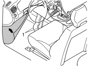
- Tip the left-hand front seat backwards
- Fold the floor carpet forward to access the air ducts (1).
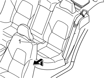
- Remove the seat cushion (1). First pull the front edge of the seat cushion up. Pull the cushion forwards. Then lift the seat cushion out.
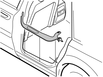
- Remove the sill moulding from the left-hand rear door.
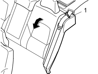
- Fold the left hand rear backrest forward
- Remove the seat belt from the guide (1).
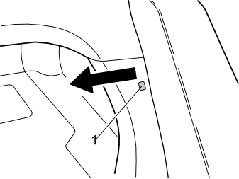
- Remove the clip (1) at the side of the left-hand side cushion
- Pull out the top edge of the left front panel in the cargo compartment to access the upper catch for the side cushion.
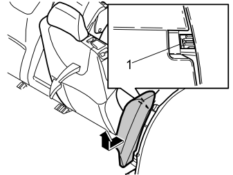
- Remove the left-hand side cushion. First press in the catches (1) at the top edge of the reverse of the side cushion. Pull the cushion out slightly
- Grasp the side cushion using both hands. Twist counter-clockwise until the catches on the inside release
- Remove the side cushion. First pull out the top of the side cushion. Then pull upwards.
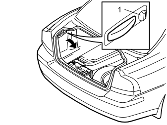
- Turn the handle (1) on the left-hand side through 90°.
- Fold the side panel inwards.
Cable routing
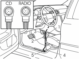
- Route the DIN cable from the kit up between the front air duct (1) and the stay (2) for the centre console.
Примечание: Ensure that the switch with the guide pin pointing upwards (see the illustration) is routed to the radio output.
- Route the cable through the radio compartment
- Clamp the cable to the stay. Use the clamp (3) from the kit
- Route the cable above and along the front air duct to the seat mounting member (4)
- Clamp the cable to the existing cable harness (5).
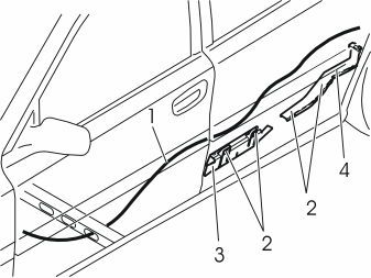
- Route the cable (1) under the carpet along the left side of the car to the rear door
- Route the cable further above and along the front cable duct (3). Continue along the right-hand side of the rear cable duct (4).
Illustration A applies to cars up to and including -2004 (CH -424999)
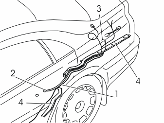
- Take the cable harness for power supply (1) from the kit. Connect the ground lead to the rear ground terminal (2) under the seat cushion. Tighten to 10 Nm (7 lbf.ft.)
- Route the cables (1, 3) along the two cable ducts (4) under the insulation panel and out through the hole in the bodywork to the cargo compartment. Position the two red/white (R/W) single cables and the two green connectors by the rear fuse holder
- Disconnect the four connectors in the front cable duct. Position the wiring under these. Reconnect the connectors again.
Illustration B applies to cars from model year 2005- (CH 425000-)
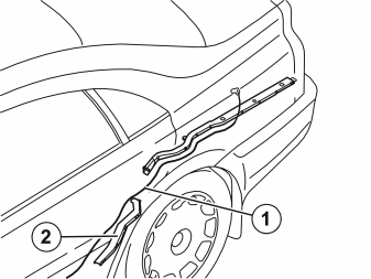
- Route the DIN cable (1) along the two cable ducts (2) under the insulation panel and out through the hole in the bodywork to the engine compartment
- Route the DIN cable under the four connectors in the front cable duct.
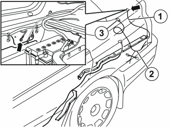
Applies to cars from model year 2005- (CH 425000-)
- Take the cable (1) for power supply from the kit. Connect the ground lead to the existing ground terminal behind the battery. Tighten the screw. Tighten to 10 Nm (7 lbf.ft.). Position the two red/white (R/W) single cables and the two green connectors (2) by the rear fuse holder
- Route the cable harness on the left-hand side of the cable duct. The cable with the blue connector (3) must be routed to the pre-routed connector for the DIN cable.
Applies to all models
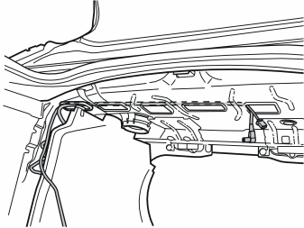
- Route the DIN cable from the kit, and the end of the power supply cable with only a blue connector, up to the parcel shelf and further as illustrated.
Примечание: The 8-pin DIN cable connector must be connected to the CD changer.
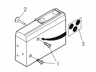
- Remove the transport screws (1.2)
- Install the dust cover (3) over the holes for the transport screws.
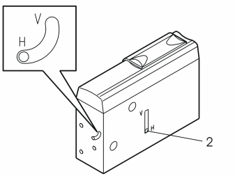
- Check that the catches (1, 2) point towards the mark H, horizontal position. If not: move the catches to the mark H.
Installing the CD changer
Примечание: It is recommended that two people drill the holes and install the CD changer.
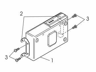
- Take the CD changer brackets and screws from the kit. Install the brackets as illustrated. Tighten the brackets using the screws.
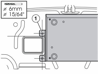
- Place the CD changer against the panel under the parcel shelf as illustrated. Hold the CD changer in position.
Примечание: Ensure that the wiring is not damaged when drilling.
Примечание: Use protective goggles if lying in the cargo compartment when drilling.
- Drill a hole through the front mounting hole of the left bracket. Use a 6 mm (15/64”) diameter drill bit
- Remove the CD changer. Smooth off the hole
- Take four screws, nuts and washers from the kit. Install the CD changer using a screw through the drilled hole. Hand tighten the screw
- Align the CD changer so that it is straight. Drill a hole through the rear mounting hole of the right bracket
- Install a screw and nut. Hand tighten
- Drill the two remaining holes. Remove the CD changer. Smooth off the holes
- Install the CD changer using four screws, nuts and washers. Tighten the screws
- Connect the DIN cable and the power supply cable to the CD changer.
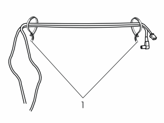
- Clamp the wiring together where it comes out of the parcel shelf.
Connection in the fuse holder
Applies to cars up to and including model year -2004 (CH -424999)
Illustration A
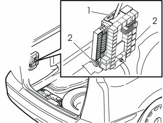
- Remove the rear electronic module (REM). First open the catch (1) on the top of the module. Fold the module forward. Lift the module from the mountings (2).
Illustration B
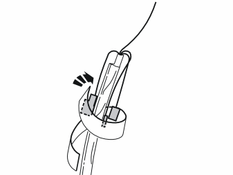
- Position both the green connectors and the red/white (R/W) single cable with the smaller cable terminal facing backwards along the cable. Insulate the cables. Secure the cables using the foam tape from the kit. They must not come into contact with the chassis. Single cable with the larger cable terminal should be loose.
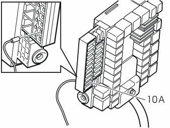
- Connect the red/white (R/W) single cable with the larger cable terminal to the fuse socket 10 on the fuse holder
- Install a 10A fuse in fuse holder 10
- Reinstall the electronic module.
Applies to cars from model year 2005- (CH 425000-)
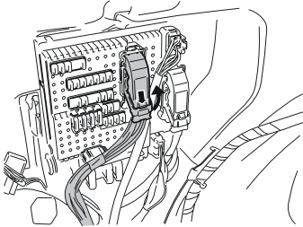
- Press in the catches on the rear brown connector in the fuse holder in the cargo compartment. Turn up the lock arm as far as possible. Pull out the connector.
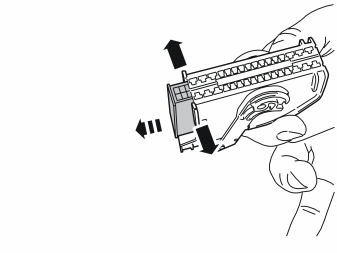
- Carefully pull apart the sides of the holder for the connector at the ends so that the connector can pass by the catches
- Pull the connector out.
- Position both the green connectors and the red/white (R/W) single cable with the larger cable terminal facing backwards along the cable. Insulate the cables. Secure the cables using the foam tape from the kit. They must not come into contact with the chassis. The single cable with the smaller cable terminal should be loose.
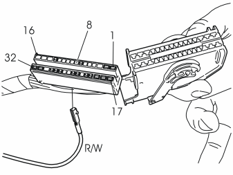
- Connect the red/white (R/W) single cable with the smaller cable terminal to position 8 in the connector
- Reinstall the connector in the holder. Reinstall the entire unit in the fuse holder.
Applies to all models
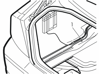
- Secure the wiring at the cable harness at the left-hand side of the rear cable duct. Clamp any cable excess.
Finishing work
Applies to cars up to and including model year -2004 (CH -424999)
- Insert the radio in the radio tray. Connect the CD changer DIN cable and the other connectors to the radio
- Connect the connectors to the phone keypad if applicable
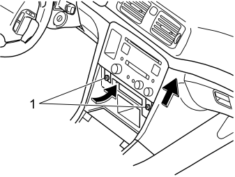
- Reinstall the bracket with the radio. Tighten the bracket and radio using the screws (1)
- Connect the connectors to the dashboard environment panel. Reinstall the dashboard environment panel
- Reinstall the panel in front of the gear selector lever.
Applies to cars from model year 2005- (CH 425000-)
- Connect the CD changer connector and the other connectors to the radio
- Connect the connectors to the dashboard environment panel
- Connect the connectors to the phone keypad if applicable
- Reinstall the radio and dashboard environment panel in the centre console. Tighten using the two screws
- Reinstall the panel around the gear selector lever.
Applies to all models
- Fold the carpet back into place
- Reinstall the centre console side panel and the sill trim panels in the left-hand front and rear doors
- Fold the front left hand seat back into position. Reinstall the screws. Tighten to 40 Nm (30 ft.lb). Reinstall the covers
- Fold the left panel in the left hand side of the cargo compartment back into place
- Reinstall the side cushion
- Fold the backrest back into place
- Reinstall the seat cushion
- Turn the ignition key to position II
- Reconnect the battery negative lead
- Reinstall the cargo compartment carpet
- Program the software according to the service information in VIDA.
Points 33-50 apply to cars with RTI: Interior preparations
- Turn the ignition key to position 0
- Remove the seat cushion (1). First pull the front edge of the seat cushion up. Pull the cushion forwards. Then lift the seat cushion out.
- Fold the left hand rear backrest forward
- Remove the seat belt from the guide (1).
- Remove the clip (1) at the side of the left-hand side cushion
- Pull out the top edge of the left front panel in the cargo compartment to access the upper catch for the side cushion.
- Remove the left-hand side cushion. First press in the catches (1) at the top edge of the reverse of the side cushion. Pull the cushion out slightly
- Grasp the side cushion using both hands. Twist counter-clockwise until the catches on the inside release
- Remove the side cushion. First pull out the top of the side cushion. Then pull upwards.
- Turn the handle (1) on the left-hand side through 90°.
- Fold the side panel inwards.
Cable routing
Applies to cars up to and including model year -2004 (CH -424999)
- Take the cable harness for power supply (1) from the kit. Connect the ground lead to the rear ground terminal (2) under the seat cushion. Tighten to 10 Nm (7 lbf.ft.)
- Route the cable (1) along the two cable ducts (4) under the insulation panel and out through the hole in the bodywork to the cargo compartment. Position the red/white (R/W) single cables and the two green connectors by the RTI/DVD-unit
- Disconnect the four connectors in the front cable duct. Position the wiring under these. Reconnect the connectors again.
Applies to cars from model year 2005- (CH 425000-)
- Take the cable (1) for power supply from the kit. Connect the ground lead to the existing ground terminal behind the battery. Tighten the screw. Tighten to 10 Nm (7 lbf.ft.). Position the red/white (R/W) single cables and the two green connectors (2) by the RTI/DVD-unit
- Route the cable harness on the left-hand side of the cable duct. The cable with the blue connector (3) must be routed to the pre-routed connector for the DIN cable.
Applies to all models
- Route the short DIN cable from the kit, and the end of the power supply cable with only a blue connector, up to the parcel shelf and further as illustrated.
Примечание: The 8-pin DIN cable connector must be connected to the CD changer.
- Remove the transport screws (1.2)
- Install the dust cover (3) over the holes for the transport screws.
- Check that the catches (1, 2) point towards the mark H, horizontal position. If not: move the catches to the mark H.
Installing the CD changer
Примечание: It is recommended that two people drill the holes and install the CD changer.
- Take the CD changer brackets and screws from the kit. Install the brackets as illustrated. Tighten the brackets using the screws.
- Place the CD changer against the panel under the parcel shelf as illustrated. Hold the CD changer in position.
Примечание: Ensure that the wiring is not damaged when drilling.
Примечание: Use protective goggles if lying in the cargo compartment when drilling.
- Drill a hole through the front mounting hole of the left bracket. Use a 6 mm (15/64”) diameter drill bit
- Remove the CD changer. Smooth off the hole
- Take four screws, nuts and washers from the kit. Install the CD changer using a screw through the drilled hole. Hand tighten the screw
- Align the CD changer so that it is straight. Drill a hole through the rear mounting hole of the right bracket
- Install a screw and nut. Hand tighten
- Drill the two remaining holes. Remove the CD changer. Smooth off the holes
- Install the CD changer using four screws, nuts and washers. Tighten the screws
- Connect the DIN cable and the power supply cable to the CD changer.
- Clamp the wiring together where it comes out of the parcel shelf.
Connecting to the DVD unit
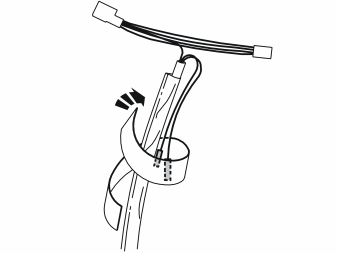
- Place the single cables back along the cable. Insulate and secure them by the cable. Use foam tape from the kit. The two green connectors must not be connected.
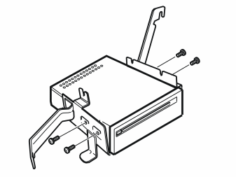
- Remove the screws (1) holding the DVD unit of the RTI system
- Pull the DVD unit out of the holder.
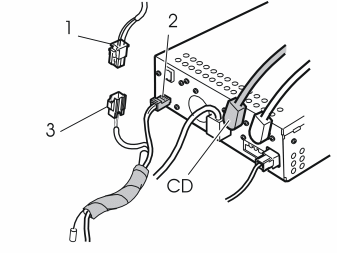
- Disconnect the connector for the DVD power supply (1)
- Connect the connector for the CD changer power supply to the DVD unit (2)
- Connect the connector previously removed from the DVD unit to the other connector (3) for the CD changer
- Replace the fuse in fuse holder 10 in the rear electronic module (REM) with a 5A fuse
- Connect the DIN cable to the DVD unit. The DIN cable is connected to the TV unit in cars which have a TV unit.
- Secure the wiring at the cable harness at the left-hand side of the rear cable duct
- Clamp any cable excess.
Finishing work
- Fold the left panel in the left hand side of the cargo compartment back into place
- Reinstall the side cushion
- Fold the backrest back into place
- Reinstall the seat cushion
- Reinstall the cargo compartment carpet
- Program the software according to the service information in VIDA.