Применимость
| Модель | Двигатель | Год |
|---|---|---|
| XC90 | — | 2003 |
Preparations
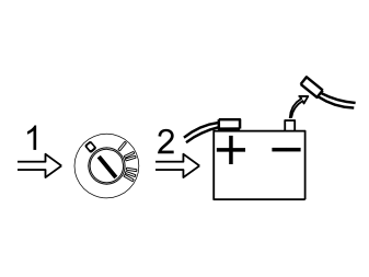
- Position the driver's seat in the rearmost position
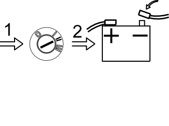
- Turn the ignition key to position 0
- Disconnect the battery negative lead.
Примечание: Wait at least five minutes before disassembling the connectors or removing other electrical equipment.
Illustration A
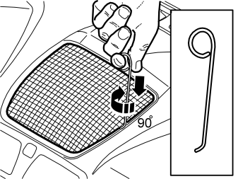
Remove the loudspeaker grille as follows:
- Take a piece of 1.5 mm (1/16”) diameter welding rod. Bend one end to 90° (L=5 mm (13/64”)). The other end is bent to form a handle
- Insert the first bent end down into the joint between the loudspeaker grille and the dashboard as illustrated, until it engages
- Twist the welding rod 90° so that the bent section engages with the underneath of the loudspeaker grille. It may be necessary to move the welding rod along the joint to twist the rod around.
Illustration B
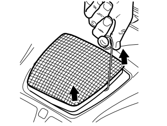
- Pull upwards until the loudspeaker grille detaches. The loudspeaker grille is securely fastened by four clips.
Примечание: Do not damage the dashboard.
- Place the loudspeaker grille to one side.
Illustration C applies to cars without a centrally-mounted loudspeaker
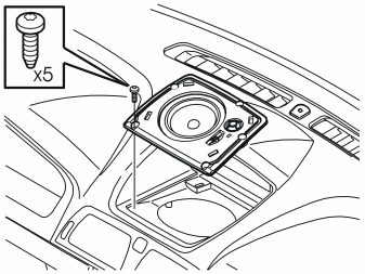
- Remove the bracket for the loudspeaker grille by removing the five screws and pulling it up out of the dashboard.
Illustration D applies to cars with a centrally-mounted loudspeaker
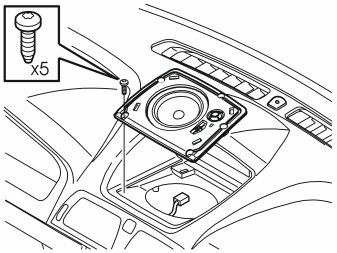
- Remove the five screws in the loudspeaker. Pull up the loudspeaker slightly from the dashboard. Disconnect the connector.
Illustration E applies to cars with RTI (road traffic information)
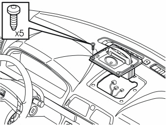
- Remove the five screws in the display for RTI (road traffic information). Pull up the display slightly from the dashboard. Disconnect the connectors. Disconnect the centrally-mounted loudspeaker connector if installed.
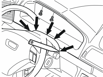
- Lower the steering wheel to the lowermost position. Pull the steering wheel to the rearmost position
- Remove the two screws at the top edge of the combined instrument panel surround
- Carefully pry off the rubber seal from the upper steering column cover. Use a weatherstrip tool. It is secured with five clips
- Remove the surround by carefully pulling it backwards, first at the lower edge and then at the top edge until all the clips have released.
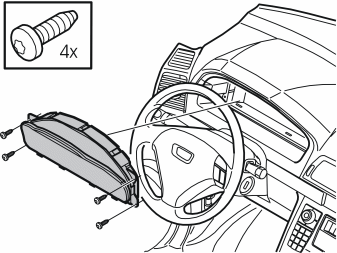
- Remove the four screws for the combined instrument panel
- Pull out the combined instrument panel. Disconnect the connector on the reverse of the combined instrument panel.
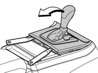
Applies to cars with automatic gearboxes
- Turn the ignition key to position II.
Applies to all models
- Move the gear selector lever to its rearmost position
- Carefully pry off the gear selector lever panel at the lower edge using a weatherstrip tool. Pull the panel backwards to access the screws for the dashboard environment panel.
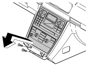
- Remove the screws holding the bracket for the dashboard environment panel and the control module
- Pull out the bracket at the lower edge. Pull downwards from the top edge of the centre console
- Disconnect the connectors from the dashboard environment panel, control module. If applicable disconnect the CD player and/or Mini disc player connectors.
Installing the carphone holder
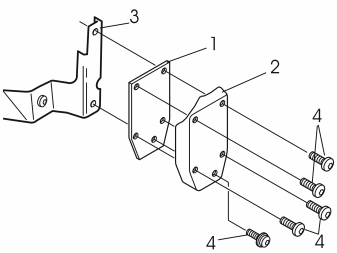
- Take the carphone holder bracket, the reinforcement panel, the cover and screws from the kit
- Install the reinforcement panel (1) and the cover (2) in the bracket (3) using the screws (4).
Illustration A
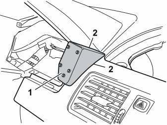
- Position the entire unit (1) in the dashboard to mark out holes for the bracket. Adjust to achieve the optimum position. Do not press the unit hard against the dashboard, however, ensure that there are no gaps at the sides between the panel and the dashboard (2).
Illustration B
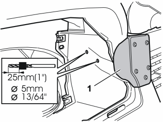
- Hold the unit securely and mark out the holes through the bracket
- Drill out the two holes using a 5 mm (13/64”) diameter drill bit. Use a 25 mm (1”) drill stop
- Remove any swarf
- Remove the cover and the reinforcement panel from the bracket.
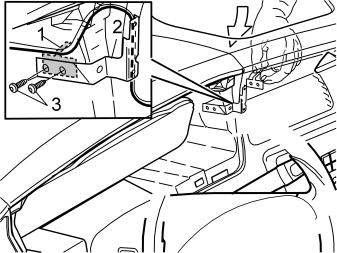
- Take the reinforcement panel (1) and the two screws from the kit
- Position the carphone holder wiring so that it is routed on the reverse of the bracket as illustrated
- Insert the reinforcement panel through the hole for the centre loudspeaker
- Install the bracket (2). Use the two screws (3). Tighten the bracket against the dashboard.
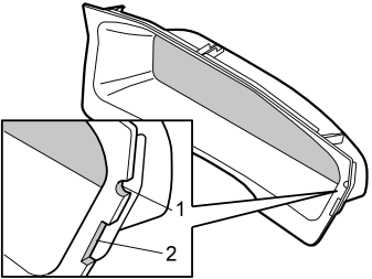
- Mark out the hole for the wiring for the handset holder and bracket on the surround for the combined instrument panel
- File out a groove (1) in the surround for the combined instrument panel for the wiring for the handset holder
- File the hole so that it is large enough for any excess wiring to be routed through the hole and hidden on the inside of the dashboard
- File out a groove (2) for the installed bracket
- Smooth off the edges of the groove.
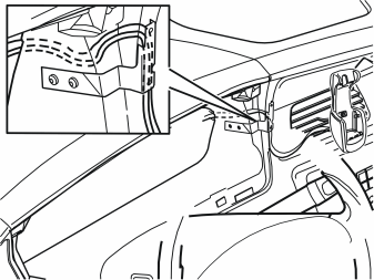
- Route the wiring to the carphone holder from the hole for combined instrument panel. Position the wiring at the left air duct in the centre console. Do not route more wiring than is required to secure the carphone holder
- Connect the combined instrument panel. Reinstall the combined instrument panel
- Reinstall the surround for the combined instrument panel. Tighten.
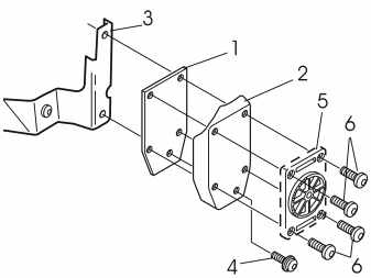
- Install the bracing plate (1) and the cover (2) in the bracket (3). Use the screw (4) (from the kit). Do not tighten fully yet
- Remove the mounting plate (5) for the carphone holder from the carphone holder. Tighten the mounting plate using the screws (6) from the kit
- Tighten the screw (4).
Illustration A applies to Nokia
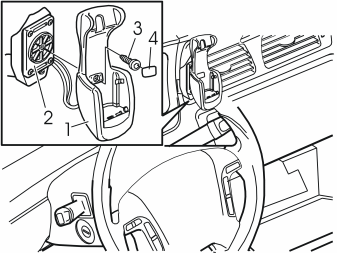
- Tighten the carphone holder (1) onto the mounting plate (2) using the screw (3)
- Install the cover (4).
Illustration B applies to the Ericsson T28, T29, T39
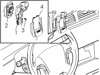
- Tighten the upper section of the carphone holder (1) onto the mounting plate (2) using the screw and washer (3)
- Press the lower section (4) of the carphone holder onto the upper section.
Illustration C applies to the Ericsson T20
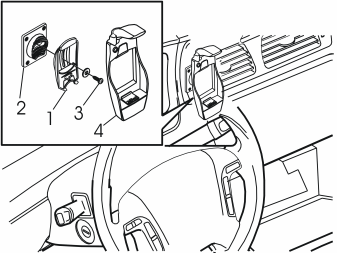
- Tighten the carphone holder mounting (1) onto the mounting plate (2) using the screw and washer (3)
- Press the carphone holder (4) onto the mounting.
- Connect the connectors to the dashboard environment panel and control module. If applicable connect the CD player and/or Mini disc player connectors
- Position the bracket. Tighten the bracket using the two screws. Reinstall the gear selector lever panel
- Reinstall (depending on the equipment of the car):
- Turn the ignition key to position II
- Reconnect the battery negative lead.
Обсуждение и оценка
0Пока нет комментариев. Будьте первым.