Применимость
| Модель | Двигатель | Год |
|---|---|---|
| C70 (06-) | — | 2006–2013 |
Preparations
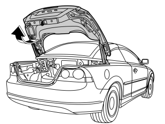
- Open the boot lid.
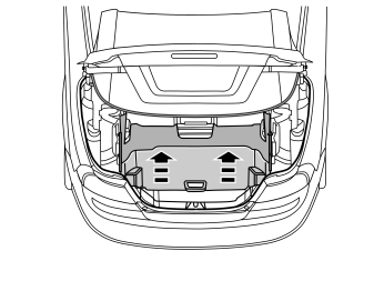
- Lift up the cargo compartment's divider.
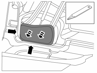
- Remove the covers on each side of the divider.
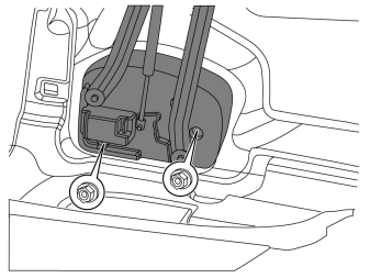
- Unscrew the two nuts on each side of the divider four turns.
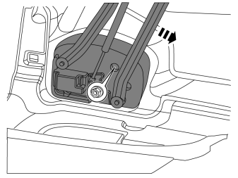
- Lower the divider slightly.
- Unscrew the third nut on each side of the divider four turns.
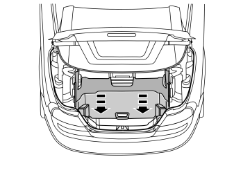
- Lower the divider completely.
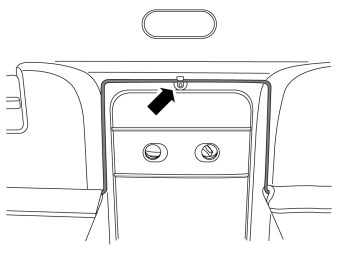
- Detach the wire frame from the clip.
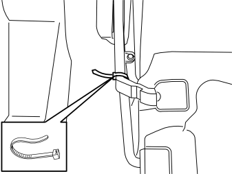
- Lock the divider's two arms, e.g., with a cable tie, on the right and left side.
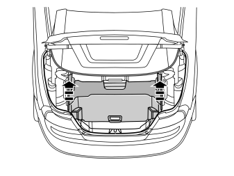
- Remove the divider by gripping the arms and lifting up.
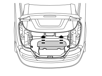
Remove:
- the cover on the tool box
- the spare wheel, if present.
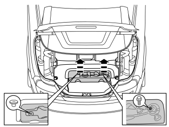
- Remove the tools from the tool box.
Remove:
- the clip
- the screw
- the toolbox.
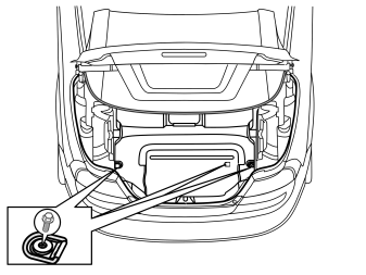
- Remove the three screws and the load retaining eyelets from the floor.
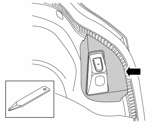
- Remove the cover from the trunk lid stop. Use a weatherstrip tool to pry between the cover and the stop to release the catches.
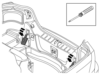
- Remove the two light bulbs by pressing in the two catches at the top with a screwdriver.
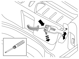
Applies to cars with emergency opening handle in the cargo compartment
- Remove the emergency opening handle by pressing out the pin at the eye and unhook the wire.
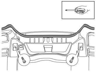
- Remove the two screws in the sill moulding.
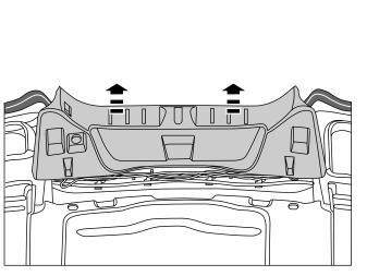
- Remove the sill protection by pulling it up until the clip releases. Fold the sill protection to the side.
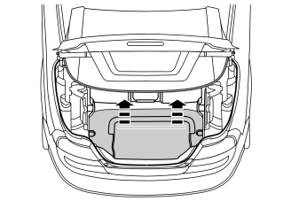
- Remove the carpet in the cargo compartment.
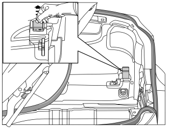
- Remove the rubber stop on the roof's stop brace.
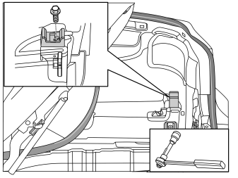
- Mark out the stop bracket for the roof in relation to the screw.
- Remove the screw and the roof's stop bracket.
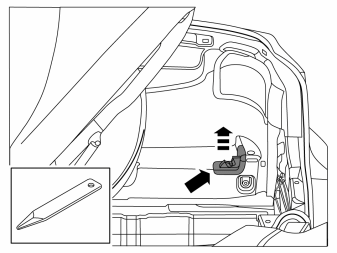
- Remove the load divider lock by using a weatherstrip tool to pry between the carpet and lock.
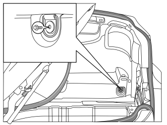
- Remove the screw and the cargo lashing eye on the right side.
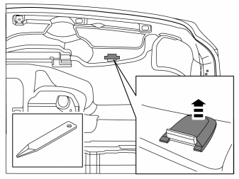
- Remove the stop brace cover.
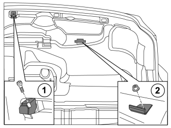
- Mark out the stop braces for the roof in relation to the screws and nuts on the right side.
- Remove the screw, nut and the roof's stop braces.
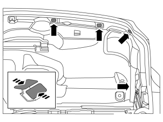
- Loosen the four clips on the right side panel.
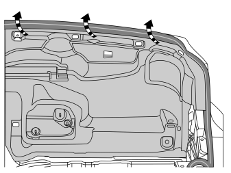
- Remove the side panel by unhooking it from the stop lug at the front edge and the pulling outward and upward so that it releases from the sealing strip.
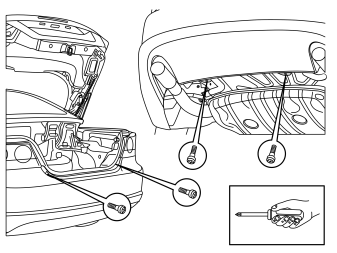
- Remove the four screws on the bumper.
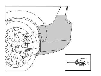
- Remove the four screws on the bumper casing's end. Repeat on the other side.
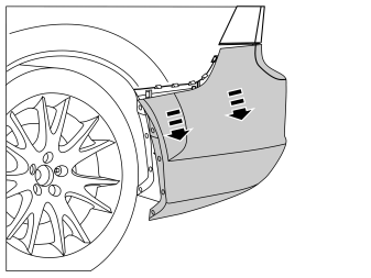
- Grab the bumper casing's end and carefully pull it outward until the six catches release. Repeat on the other side.
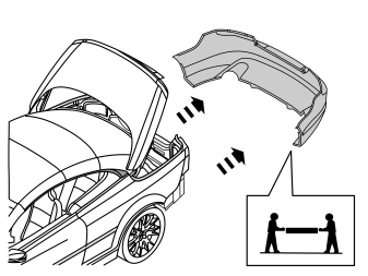
- Pull the bumper straight backward until the catches under the tail lights release.
Примечание: It is easier to remove the bumper if two persons help each other.
- Place the bumper on a surface that does not damage the paint.
Installing trailer socket
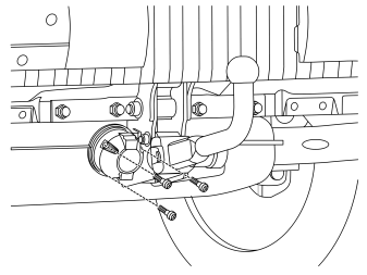
- Install the trailer socket on the bracket with screws and nuts from the kit.
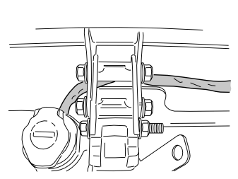
- Route the cable harness between the body and the trailer hitch. Route it against the body's right side, on the underside of the bumper member's right attachment to the rubber leadthrough.
Примечание: Note the routing of the cable harness at the centre of the towbar.
- Secure the cable harness on the trailer hitch with a cable tie.
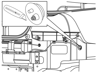
- Cut off the end of the largest pin on the rubber leadthrough.
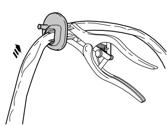
- Use pliers, part no. 9987596, to expand the hold in the rubber leadthrough.
- Pull the cable harness through the rubber leadthrough.
- Adapt the cable harness length so that it reaches the hole in the body.
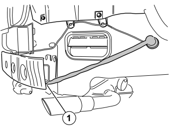
- Secure the cable harness on the bumper member's bracket with two joined cable ties (1).
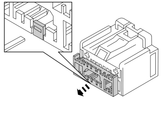
- Take the connector from the kit. Press down the catch with a small screwdriver and pull out the connector's lock.
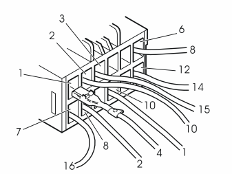
- Install the ends of the cables for the trailer hitch cable harness in the connector as follows:
| Position | Cable | Function |
|---|---|---|
| 1 | 4 | Right indicator lamps |
| 2 | 10 | Charging |
| 3 | 15 | Left brake lamp |
| 6 | 8 | Reversing lamp |
| 7 | 16 | Right brake lamp |
| 8 | 2 | Fog lights |
| 10 | 1 | Left indicator lamps |
| 12 | 14 | Position lamps |
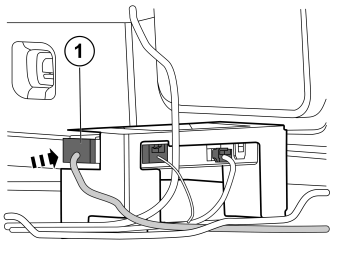
- Connect the connector (1) to the trailer module (TRM).
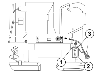
- Remove the nut (1).
- Clean the stud (2) from paint.
- Connect the ground cable (3) from the routed cable harness. Torque the nut with 10 Nm (7 lbf.ft.).
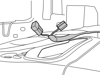
- Pull the trailer hitch wiring further along the car's cable harness up to the sill moulding.
Reinstall:
- the bumper
- the side panel
- the stops and attaching braces
- the luggage compartment mat
- the lashing eyes - tighten the screws to 24 Nm (17 lbf.ft)
- the toolbox.
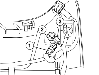
- Remove the connector (1) on the 12 V socket of the sill panel and connect it to connector (2).
- Connect the connector (3) for the 12 volt socket
- Secure the loose connector with a cable tie.
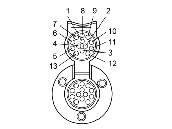
Check the 13-pin socket.
Примечание: To obtain the correct function, the trailer module (TRM) must be programmed with software.
| Position | Function |
|---|---|
| 1 | Left indicator lamps |
| 2 | Rear fog lamp |
| 3 | Ground |
| 4 | Right indicator lamps |
| 5 | Right rear position lamp |
| 6 | Brake lamp |
| 7 | Left rear running light |
| 8 | Reversing lamp |
| 9 | Power supply |
| 10 | Charging |
| 11 | Charging ground |
| 12 | Trailer indicator |
| 13 | Ground |
Reinstall:
- the sill panel with lighting
- emergency opener, if present
- the stop for the trunk lid
- the divider; remove the cable ties.
Обсуждение и оценка
0Пока нет комментариев. Будьте первым.