Применимость
| Модель | Двигатель | Год |
|---|---|---|
| XC60 | — | 2014–2015A |
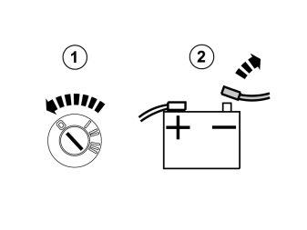
- Turn the ignition key to position 0.
- Disconnect the battery negative lead.
Примечание: Wait at least three minutes before unplugging the connectors or removing other electrical equipment.
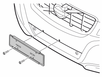
- Remove the number plate and holder.
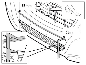
- Apply the strips of tape as illustrated.
- Measure out the indicated measurements from the upper edge of the lower grille and remove the ends of the tape strips.
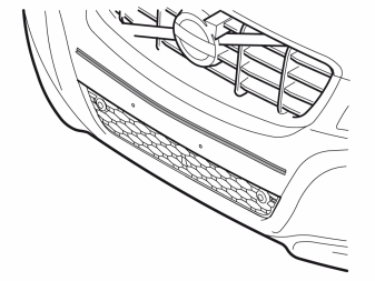
- Join both markings.
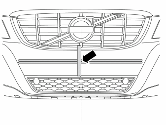
- Now mark the centre of the bumper cover with one edge of the strip of tape.
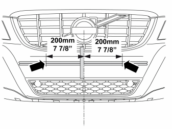
- Measure 200 mm (7 7/8 ") from the centre of the bumper cover and outwards and remove the long strips of tape on both side.
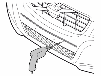
- Carefully drill the markings at the sides using the designated drill bit Ø 8.5 mm (21/64") and L=240 mm (9 7/16")
Примечание: It is important that the holes are drilled horizontally to the car.
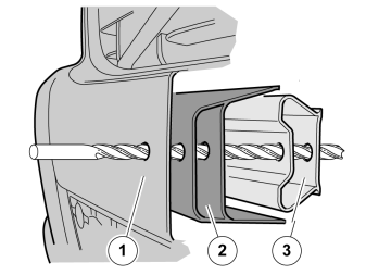
- Through the bumper cover
- The impact absorption area
- The impact member
Примечание: It is important that the holes are drilled horizontally to the car.
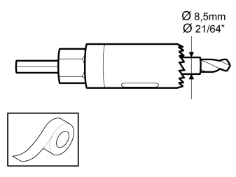
- Take a Ø 22 mm (7/8 ") hole saw and tape the centre drill to approx. Ø 8.5 mm (21/64").This is to get the hole saw to centre in the drilled hole.
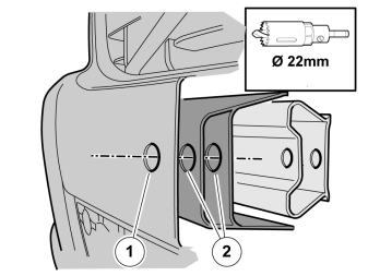
- Open out the hole in the bumper cover (1) and the impact absorption area (2) on both sides using the hole saw Ø 22 mm (7/8").
Примечание: Do not drill through the impact member.
- Remove the tape strips.
Applies to cars without turbocharger
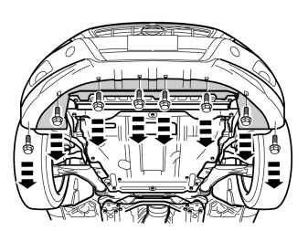
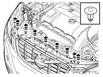
- Remove the eight screws in the air baffle.
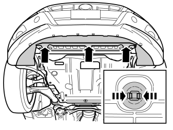
- Remove the three clips by pressing together the fasteners and pulling them away.
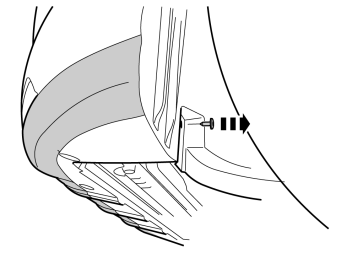
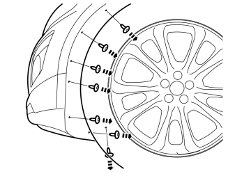
- Remove the two screws for the lower air baffle on the front edge of the wheel housing on both sides.
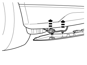
- Loosen the air baffle so that the connectors on the inside of both sides can be removed.
- Remove the connectors with cable from the right-hand inside of the air baffle.
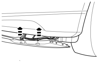
- Disconnect the cable harness and the washer hoses with clips from the air baffle's left-hand inside.
- Remove the air baffle.
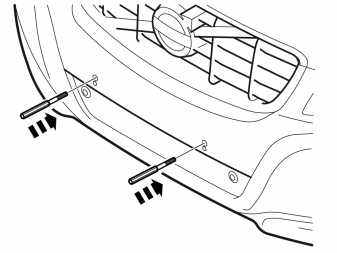
- Install the spacers.
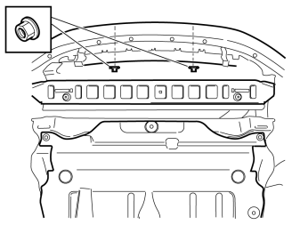
- Install the two nuts from below.
Tightening torque: 24 Nm (17.7 Ibf.ft.).
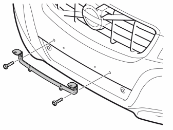
- Install the console.
- Install the screws.
- Install the number plate
Applies to cars with turbocharger
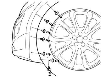
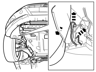
- Fold back the wing liner.
- Loosen the connector and wiper hose to the headlight's high pressure washer.
- Place a container underneath to collect the washer water or seal the outlet on the washer pump.
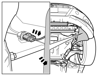
- Fold back the wing liner.
- Loosen the connector on the inside of the air guide.
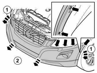
Подсказка: The following procedure should be performed by two people.
- Unhook the end of the bumper cover at the rear edge from the hooks on both sides (small picture). Carefully pull off the ends, they are secured by two clips on the front wing and three below the headlight.
- Pull loose the bumper cover forward in one piece.
- If the car is equipped with fog lamps, loosen the connectors to these.
- Remove the bumper cover.
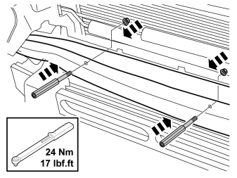
- Install the two spacer screws in the impact member together with the two nuts on the rear.
- Tighten to a torque of 24 Nm (17.7 Ibf.ft). Use a torque wrench, tighten from the front and counterhold the nuts at the rear.
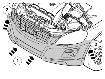
Подсказка: The following procedure should be performed by two people.
- If the car is equipped with fog lamps, connect the connectors to these.
- Reinstall the bumper cover and make sure that all catches engage.
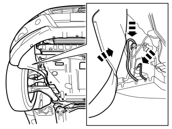
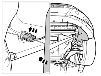
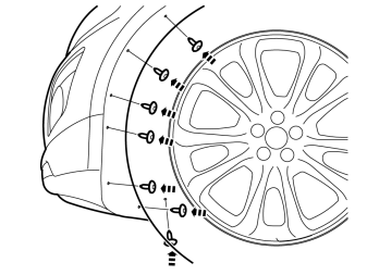
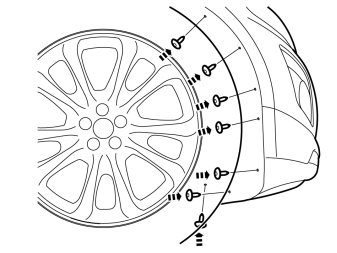
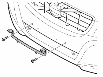
- Install the console.
- Install the screws.
- Install the number plate
Applies to all cars
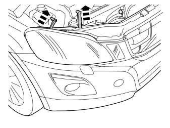
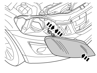
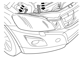
- Pull out the two lock pins from the right-hand headlamp.
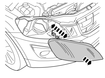
- Pull out the headlamp some distance and detach the connector on the rear. Place the headlamp to one side.
- Repeat the operation on the other side.
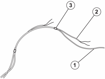
- In order to facilitate cable routing, tape the red cable (1) together with the longer auxiliary lights' cables, black and blue (2). Finally, tape the ends of the shorter auxiliary lights' cables (3).
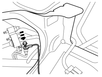
- Undo the front ground screw inside the right-hand headlamp.
- Take out the new cable harness and connect the ground cable and tighten the bolt to 10 Nm (7.3 Ibf.ft).
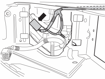
- Install the relay on the cable harness.
- Secure the relay and socket onto the car's existing cable harness using two tie straps.
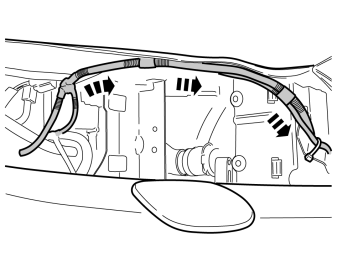
- Route the cable harness under the front plate.
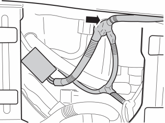
- Secure the cable harness branching point at the rear edge of the front plate using butyl tape.
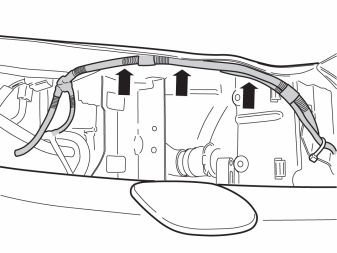
- Secure the cable harness using butyl tape.
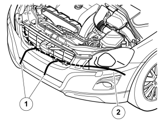
- Pull the taped cables, black and blue, through the wider holes in the grille (1). The red cable is routed by the left-hand headlight (2).
- Route the cables using a wire or string.
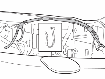
- Secure the cable harness with a tie strap.
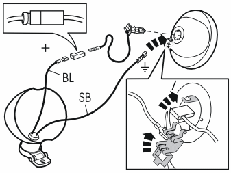
The illustration shows an outline of the connection of the auxiliary lights. See the separate instructions for the complete method.
- Thread the cables through the lamp housing.
- Install cable terminals onto both cables.
- Fit a socket housing to the blue (BL) cable to avoid short circuits.
- Connect the blue (BL) cable to the lamp's cable.
- Connect the black (SB) cable to ground on the light insert.
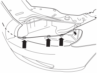
- Route the cable harness to the fuse holder. Secure the cable harness using butyl tape.
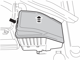
- Remove the cover from the fuse box.
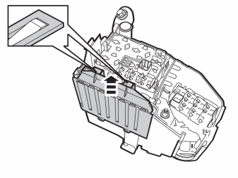
- Remove the cover.
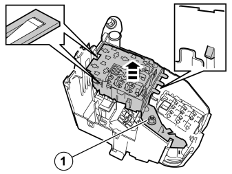
- Undo the nut (1).
- Loosen the locking catches and pull up the right-hand fuse/relay holder.
Примечание: There are two catches on the long side.
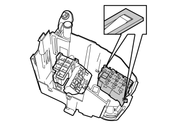
- Push in the locking catches and lift up the left-hand fuse holder.
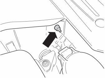
- Cut off the rubber teat.
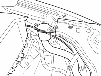
- Thread the cable harness through the rubber grommet.
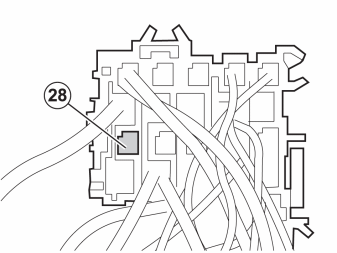
- Turn the left-hand fuse holder over. Install the red (RD) cable in position 28.
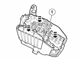
- Reinstall the detached components in reverse order.
Примечание: Check that guides and rubber seals are fitted correctly, and that the cables do not become trapped.
- Reinstall the nut (1). Tightening torque 10 Nm (7.3 Ibf.ft).

- Install the fuse in position 28.
- Reinstall the cover.
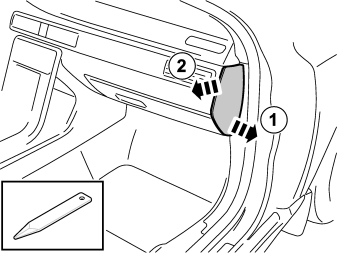
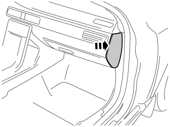
- Remove the right end panel of the dashboard.
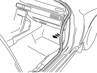
- Detach the moulding on the front edge of the door opening.
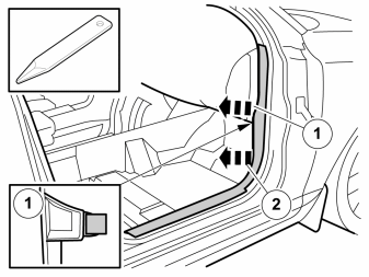
Примечание: The front and upper sill panel must be removed and installed as one unit.
- Pull the sill panel backwards with a weatherstrip tool so that the two clips release.
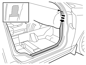
- Unhook the panel at the top.
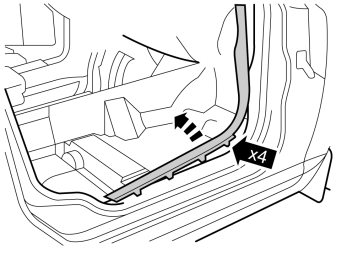
- Pull up so that the four clips release.
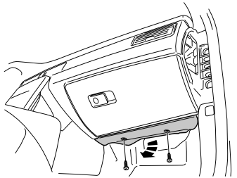
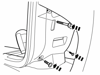
- Remove the screws and the panel.
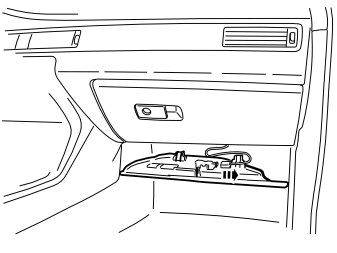
- Unplug the connector for the lighting.
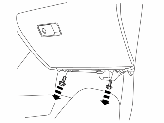
- Remove the two screws.
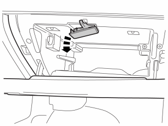
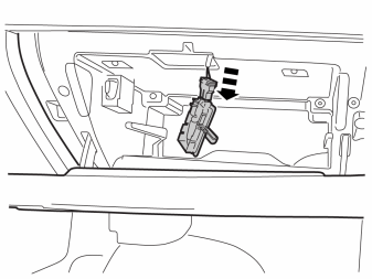
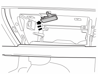
- Carefully pry off the glovebox lighting.
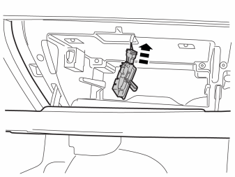
- Loosen the connector from the lamp in the glovebox lighting, it may be tight.
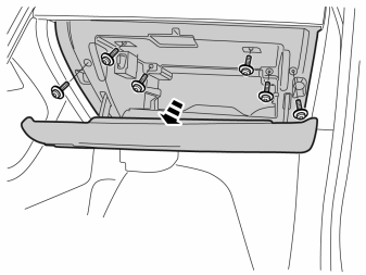
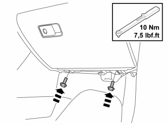
- Remove the six screws.
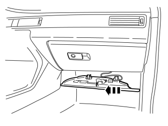
- Pull out the glovebox a little and if necessary loosen the connector on the Sim card holder at the rear.
- Remove the glovebox.
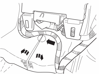
- Move the carpeting aside. Make a cut in the thick insulating mat starting level with the blue connector of the central electronic module (CEM) and then continue straight down.
- Move aside the insulating mat to access the grommet.
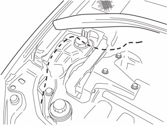
- Route the green (GN) cable backwards and down to the rubber grommet.
- Secure the cable with cable ties so that it is not crushed or risks being broken.
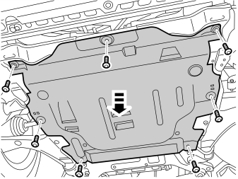
- Raise the car and remove the engine splash guard.
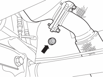
- Remove the existing rubber grommet.
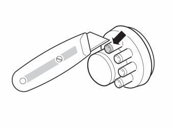
- Cut off a small rubber teat on the new rubber grommet and thread through the cable. Route the cable into the passenger compartment.
- Install the rubber grommet.
- Reinstall the engine splash guard and the cover panel.
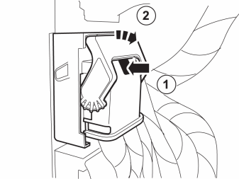
- Unplug the green connector on the Central Electronic Module (CEM).
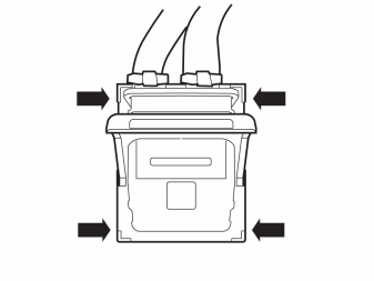
- Remove the connector's cover by lifting the four hooks.
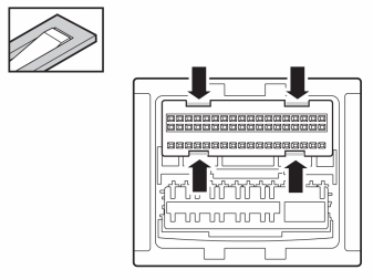
- Lift at the four hooks and remove the catch.
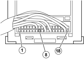
- Connect the green (GN) cable to position 8.
- Reinstall the lock.
- Reinstall the cover.
- Plug in the connector.
- Fold back the carpet.
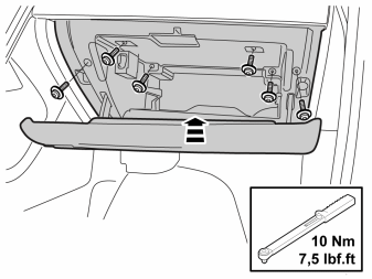
- Take the glovebox and connect the connector to the Sim card holder, if necessary.
- Insert the connector to the glovebox lighting.
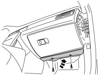
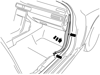
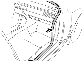
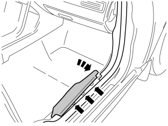
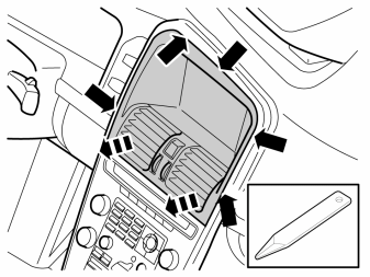
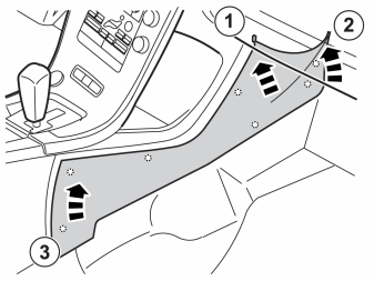
- Carefully pry off the panel all round, it is secured by five clips on the sides and at the top and with four catches on the bottom edge.
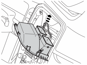
- Pull out the panel and disconnect the connector for the hazard warning lights.
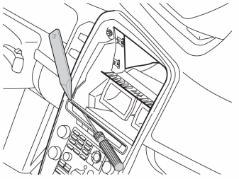
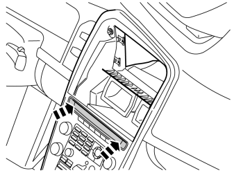
- Insert a screwdriver into the media player gap.
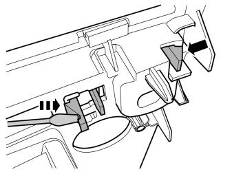
- Push in the catch and carefully pry off the surround on one side using a weatherstrip tool. Repeat on the other side and remove the panel.
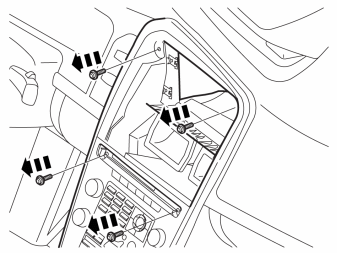
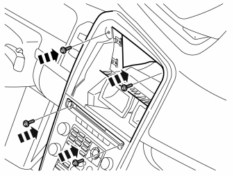
- Remove the four screws on the top edge of the panel.
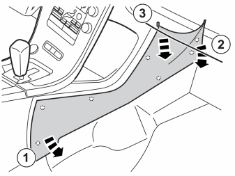
- Remove the tunnel console's panel on both sides. It is secured by seven clips on the inside.
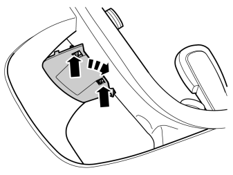
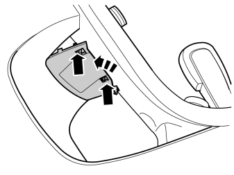
- Push in the catches on the cover, fold it downwards and remove.
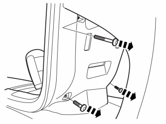
- Remove the three screws at the rear of the centre console.

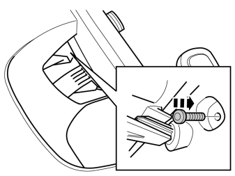
- Remove the last screw at the rear of the centre console.
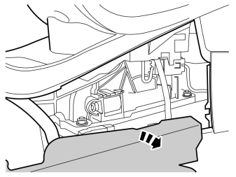
- Fold the floor mat to one side by the left-hand side of the tunnel console.
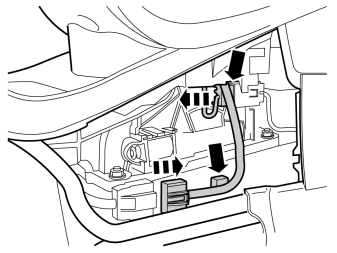
- Loosen the clips on the cable harness from the tunnel console.
- Disconnect the connectors for the CCM.
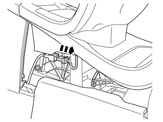
Applies to cars with an CCD keypad
Applies to cars with automatic transmission
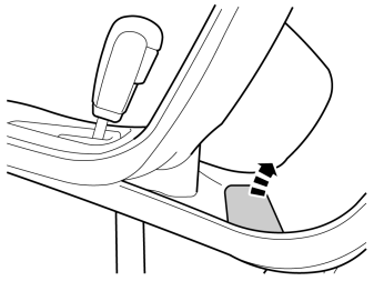
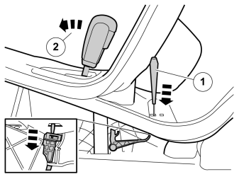
- Release the shift-lock function.
- Place the gearshift in position "D".
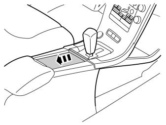
Applies to all cars
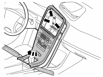
- Carefully pry off the centre console panel. Start at the rear edge on both sides, it is secured with two clips on the long sides and with four catches around the gearshift panel and two catches at the top.
- Lift up the panel a little and make sure that all cables are free from the gear lever carrier and components in the tunnel console and then lift it out.
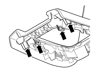
- Make a note of the clips.
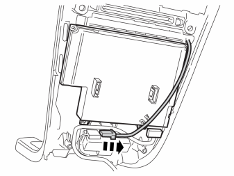
- Loosen the connector from the keypad.
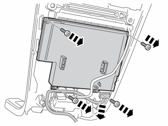
- Remove the four screws holding the CCM in place.
- Pull it out a little and loosen the green connector on the lower edge. The connector's catch is at the rear.
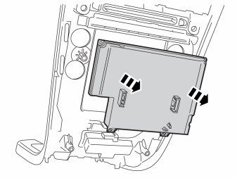
- Remove the CCM from the panel.
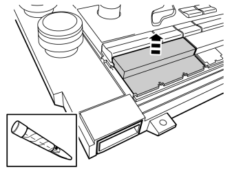
- Remove the cover.
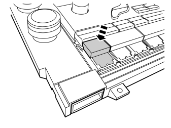
- Install the switch. It must be fitted in the first available button location seen from the steering wheel.
Примечание: Cover plugs are purchased separately.
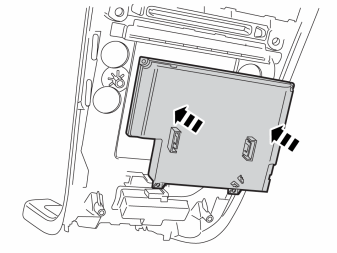
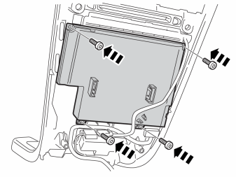
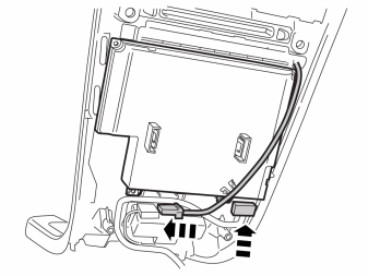
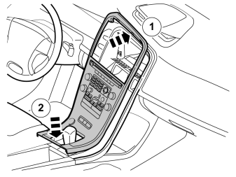
- Take the panel with CCM and insert the cables in the tunnel console.
- Place it on the top edge and secure with clips on the rear edge.
- Secure the panel in the centre console/tunnel console. Make sure that all clips engage.
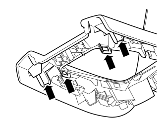
- Secure the panel in the centre console/tunnel console. Make sure that all clips engage.
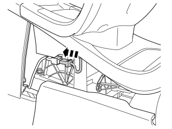
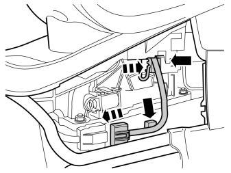
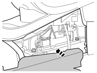
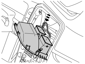
- Connect the connector to the warning flashers.
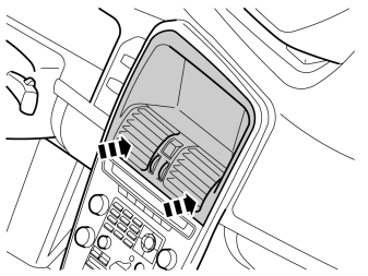
- Install the top panel. Make sure that all air nozzles align correctly in the air ducts in the dashboard and that all clips and catches engage.
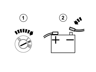
- Reconnect the battery negative lead
- Turn the ignition key to position II.

- Download the software for the accessory's function following the service information in VIDA.
Обсуждение и оценка
0Пока нет комментариев. Будьте первым.