Применимость
| Модель | Двигатель | Год |
|---|---|---|
| S80 (07-) | — | 2014–2015A |
| V70 (08-) | — | 2014 |
| XC70 (08-) | — | 2014–2015A |
Removal
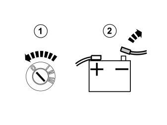
- Turn the ignition key to position 0.
- Remove the cover for the battery box and then the battery's negative lead.
Примечание: Wait at least three minutes before unplugging the connectors or removing other electrical equipment.
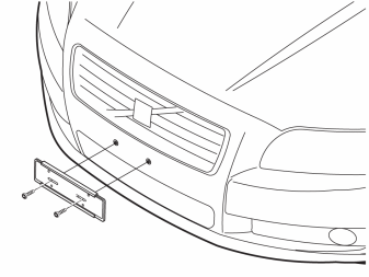
- Remove the number plate and holder.
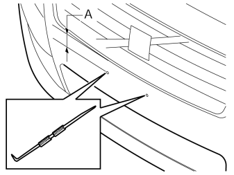
- Locate the two markings that are situated according to the measurement A in the image under the top edge of the outer cover. Make holes in the markings with a scriber.
S80
- A = 100 mm
V70
- A = 100 mm
XC70
- A = 81.5 mm
Accessory installation
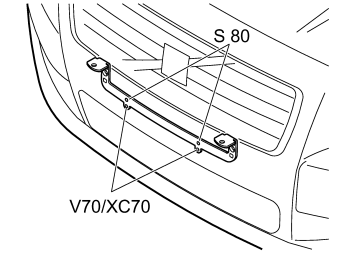
- Tighten the cover. The upper holes apply to the S80, the lower for V70/XC70. Use new screws from the kit.
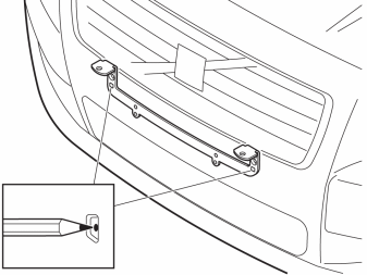
- Mark the centre of the lower holes.
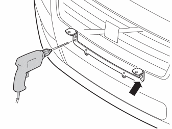
- Drill into the markings with the designated drill bit.
Примечание: It is important that the holes are drilled horizontally to the car.
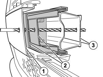
- Drill through the outer cover
- The shock absorbing section
- The impact member
- Remove the bracket.
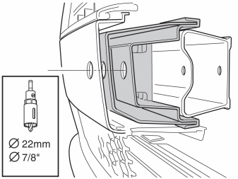
- Drill out the holes using a 22 mm 7/8" hole saw through the outer cover and the shock absorbing section.
Примечание: Do not drill through the impact member.
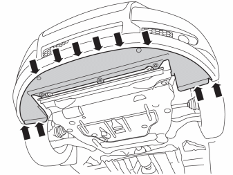
- Remove the screws.
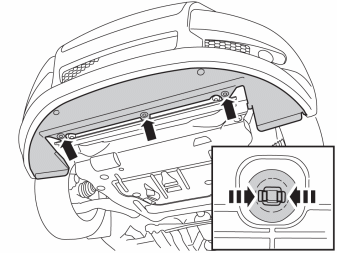
Remove:
- the clips by pinching the catches and then pulling them out.
- the cover panel.
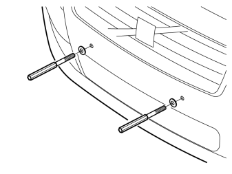
Install:
- the washers.
- the spacers.
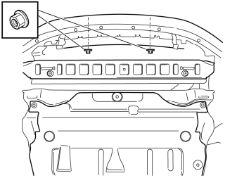
- Install two nuts from below, tightening torque: 24 Nm (17.7 lbf.ft.)
Applies to the S80 and XC70
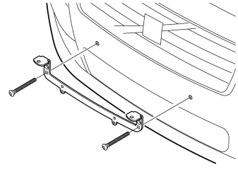
Install:
- the bracket.
- the screws.
- registration plate
Applies to the V70
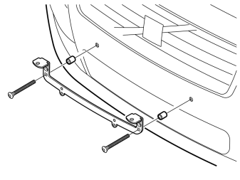
Install:
- the spacers.
- the bracket.
- the screws
- registration plate.
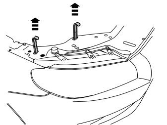
- Remove the lock facings from both headlamps.
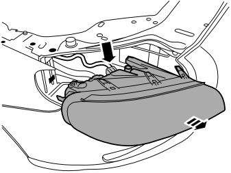
- Remove both headlamps.
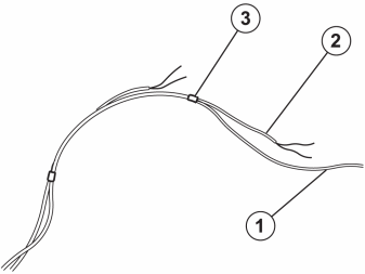
- In order to facilitate cable routing, tape the red cable (1) together with the longer auxiliary lights' cables (2), black and blue. Finally, tape the end of the shorter auxiliary lights' cables (3).
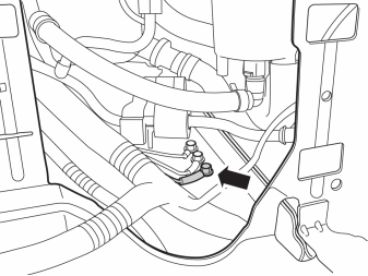
- Undo the front ground screw inside the right-hand headlamp.
- Connect the ground lead and tighten the screw to 10 Nm (7.3 lbf.ft).
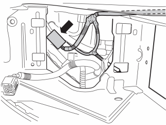
- Connect the relay to the cable harness.
- Secure the relay and socket onto the car's existing cable harness using two cable ties.
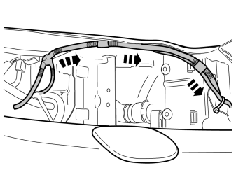
- Route the cable harness under the front plate.
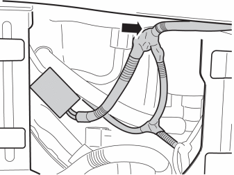
- Secure the cable harness branching point at the rear edge of the front plate using butyl tape.
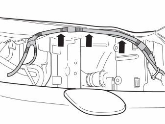
- Secure the cable harness under the front plate using butyl tape.
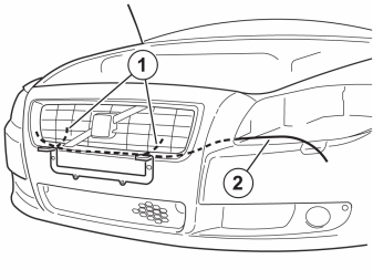
- Route the cables taped together from below,
Подсказка: Cars with intercooler (turbo)
- Route the cables using a wire or string.
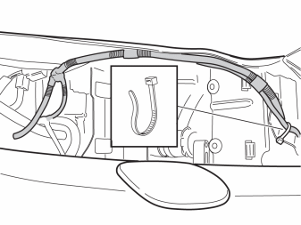
- Secure the cable harness using a cable tie to the horn's bracket.
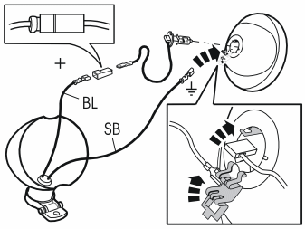
The illustration shows an outline of the connection of the auxiliary lights. See the separate instructions for the complete method.
- Thread the cables through the lamp housing.
- Install cable terminals onto both cables.
- Fit a socket housing to the blue (BL) cable to avoid short circuits.
- Connect the blue (BL) cable to the lamp's cable.
- Connect the black (SB) cable to ground on the light insert.
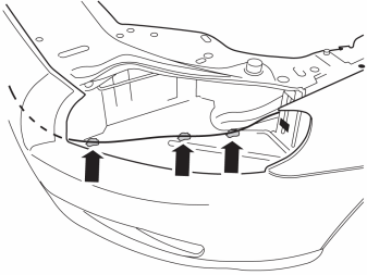
- Route the cable harness to the fuse holder. Secure the cable harness using butyl tape.
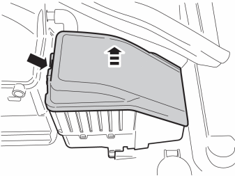
- Remove the cover.
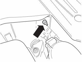
- Cut off the rubber teat.
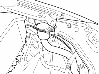
- Thread the cable harness through the rubber grommet.
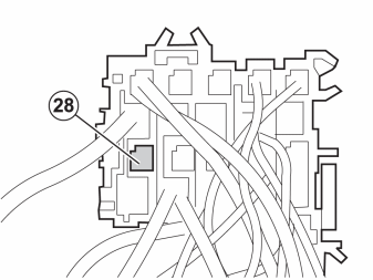
- Turn the left-hand fuse holder over. Install the red (RD) cable in position 28.
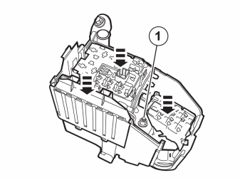
- Reinstall the detached components in reverse order.
Примечание: Check that guides and rubber seals are fitted correctly, and that the cables do not become trapped.
- Reinstall the nut (1), tightening torque: 10 Nm (7.3 lbf.ft).

- Install the fuse in position 28.
- Reinstall the cover.
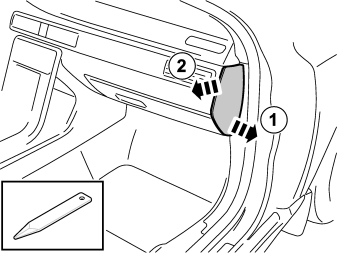
- Remove the right end panel of the dashboard.
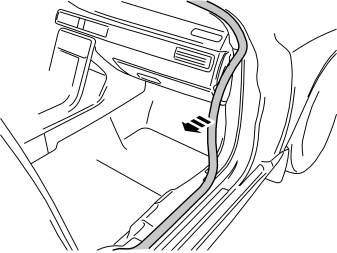
- Detach the moulding on the front edge of the door opening.
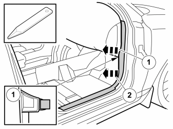
Примечание: The front and upper sill panel must be removed and installed as one unit.
- Pull the sill panel backwards with a weatherstrip tool so that the two clips release.
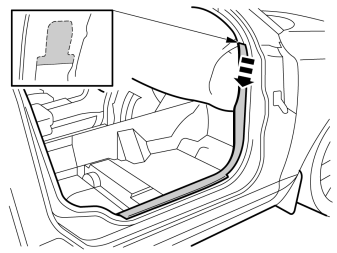
- Unhook the panel at the top.
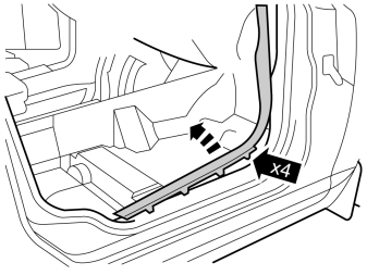
- Pull up so that the four clips release.
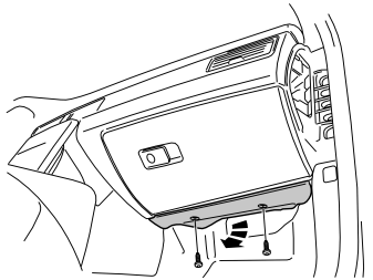
- Remove the screws and the panel.
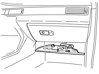
- Unplug the connector for the lighting.
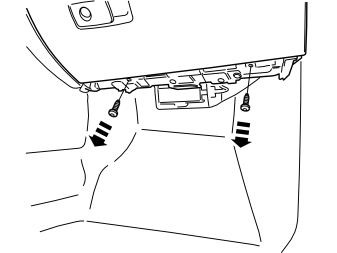
- Remove the two screws.
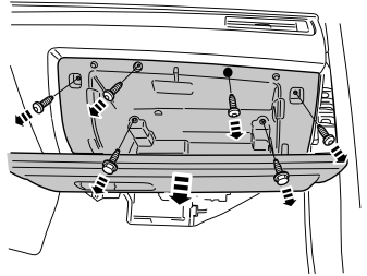
- Remove the seven screws.
- Pull the glovebox out slightly and unplug a connector on the back.
- Remove the glovebox.
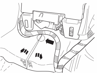
- Move the carpeting aside. Make a cut in the thick insulating mat starting level with the blue connector of the central electronic module (CEM) and then continue straight down.
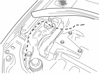
- Route the green (GN) cable backwards and down to the rubber grommet.
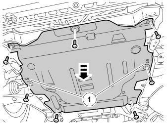
- Raise the car and remove the engine splashguard. Secured by hooks on the inside of the engine splashguard by the screws (1).
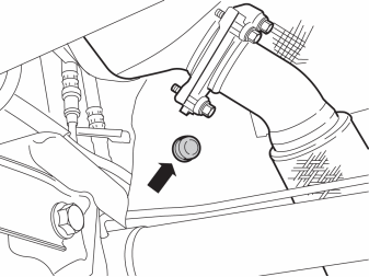
- Remove the existing rubber grommet.
On certain engine versions the grommet is hidden by a heat shield.
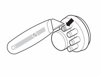
- Cut off a small rubber teat on the new rubber grommet and thread through the cable. Route the cable into the passenger compartment.
- Install the rubber grommet.
- Reinstall the engine splash guard and the cover panel.
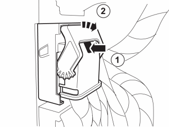
- Unplug the green connector on the Central Electronic Module (CEM).
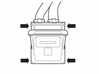
- Remove the connector's cover by lifting the four hooks.
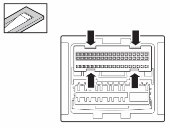
- Lift at the four hooks and remove the catch.
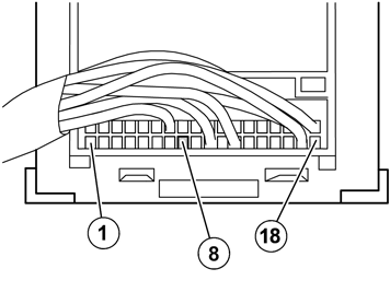
- Connect the green lead (GN) to position 8.
Reinstall:
- the catch
- the cover
-
the connector
-
Fold back the carpet.
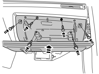
- Reinstall the glovebox and torque tighten the M6 screws to 10 Nm (7.5 lbf.ft).
- Connect the connector to the reverse of the glovebox.
- Install the screws in the lower edge.
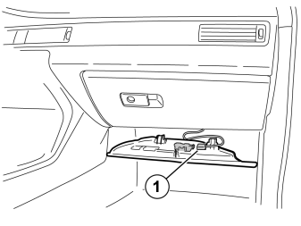
- Connect the connector (1) to the courtesy lighting and reinstall the panel.
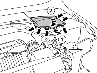
- Connect the battery negative lead.
- Reinstall the battery box cover.
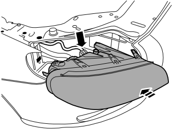
- Reinstall the headlamps.
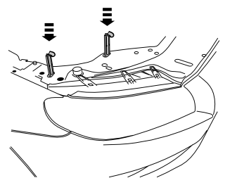

- Program the software in accordance with the service information in VIDA.
Обсуждение и оценка
0Пока нет комментариев. Будьте первым.