Применимость
| Модель | Двигатель | Год |
|---|---|---|
| S60 (-09) | — | 2001–2009 |
| S80 (-06) | — | 1999–2006 |
| V70 (00-08) | — | 2000–2008 |
| V70 XC (01-) / XC70 (-07) | — | 2001–2007 |
| XC90 | — | 2003–2015 |
Installation of installation kit
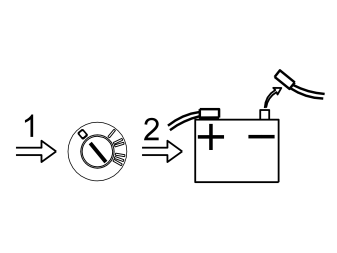
- Turn the ignition switch to position 0.
- Disconnect the battery negative lead.
Примечание: Wait at least five minutes before disassembling the connectors or removing other electrical equipment.
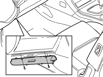
- Remove the screws and the soundproofing panel on the driver's side.
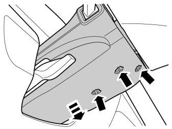
- Unscrew the three screws and remove the lower cover for the steering column.
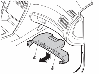
- Remove the screws and the soundproofing panel on the passenger side.
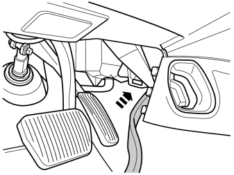
- Take the cable harness from the kit and insert it through the opening in the central stack as illustrated.
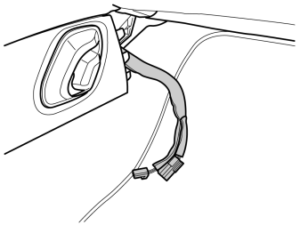
- Route the cable harness straight through the central stack and out through the opening on the other side as illustrated.
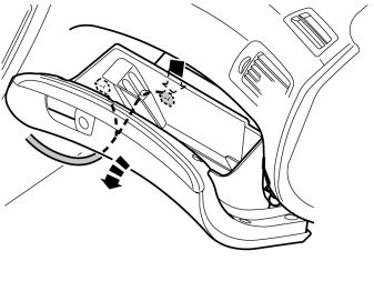
- Open the glove box.
- Locate the existing connector for the glove box lighting. It is inside the glove box but can be reached through the opening in the end piece of the glove box.
- Connect the connector from the cable harness to the existing connector. Place the wiring and connectors in their original position inside the glove box.
- Reinstall the soundproofing panel and tighten it with the screws.
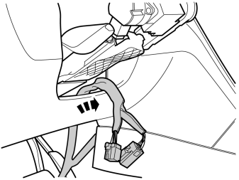
- Pull the cable harness up into the dashboard and out through the hole under the steering column.
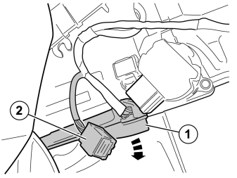
- Remove the cable duct (1).
- disconnect the existing connector for the ignition switch (2).
Примечание: Pull the newly routed cable harness between the cable duct and steering column.
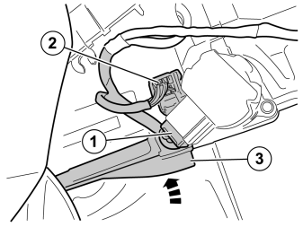
- Connect one connector from the cable harness to the ignition switch (1).
- Connect the other connector from the cable harness to the connector that was disconnected from the ignition switch. Install the assembled connectors between the steering shaft and cable duct (2).
- Reinstall the cable duct (3)
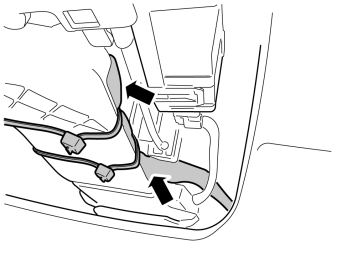
- Tighten the cable harness at the cable duct using tie straps and ensure that the catches are located on the underside of the cable duct.
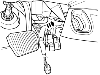
- Gather the excess and remaining connectors on the cable harness and place under the heater unit.
- Reinstall the sound proofing panel and tighten it with the screws.
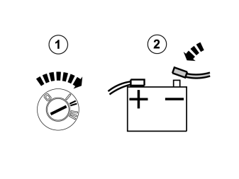
- Turn the ignition key to position II.
- Connect the battery negative lead.
Position description of connectors for alcolock
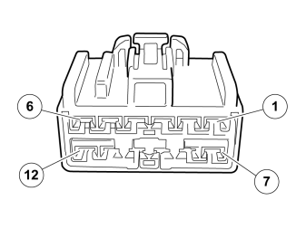
- 1 - 30+ FEED (Battery supply)
- 2 - 15+ FEED (Ignition supply)
- 3 - START-IN (kl50)
- 4 - START-OUT (kl 50)
- 5 - Preheat, act-low
- 6 - GROUND- (ground 31)
-
7 - 30+ FEED, CONTROLLED (controlled 30+ battery supply)
-
Примечание: > 30+ battery supply ( 1) must only be used in exceptional cases when log function for disconnection of the alcolock is required. In all other cases, 30+ battery supply (7) should be used, to prevent shortening the service life of the battery.
Обсуждение и оценка
0Пока нет комментариев. Будьте первым.