Применимость
| Модель | Двигатель | Год |
|---|---|---|
| C30 | — | 2007–2013 |
Applies to all models
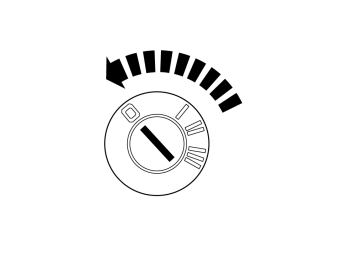
Примечание: Wait at least three minutes before unplugging the connectors or removing other electrical equipment.
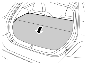
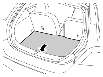
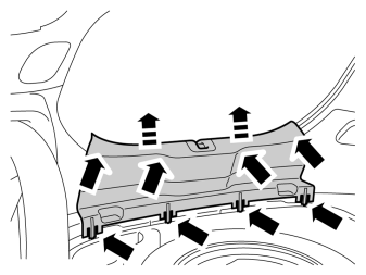
- Remove the tailgate's sill panel by pulling it up until the four clips on the upper side and the eight catches at the lower edge release.
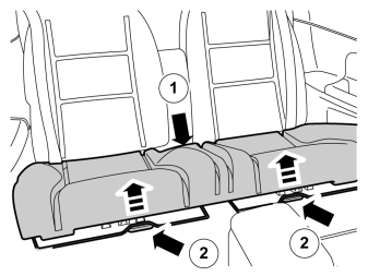
- Pull off the rear seat's seat cushion by first pulling it at the rear edge where it is positioned with a holder, then at the front edge where it is positioned with two holders.
- Remove the seat cushion.
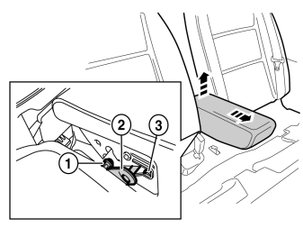
- Fold the central arm rest forward.
- Remove the central arm rest by grasping each end and pulling upwards until it releases at the rear edge from the backrest's lugs (1).
- Then pull forwards until the holders (2) on the sides of the backrest have slid out of the corresponding cut-out (3) in the central arm rest.
- Fold the backrest forward.
- Remove the cover for the backrest's right-hand mounting.
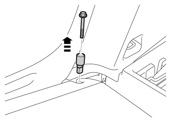
- Remove the screws and the locking sleeve. Tightening torque 15 Nm (11.0 lbf.ft.).
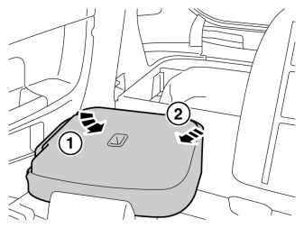
- Fold the backrest away from the right-hand mounting.
- Pull the backrest out from the mounting at the arm rest and remove it.
Примечание: The backrest may be securely attached.
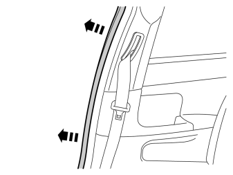
- Pull off the rubber molding at the rear edge of the right-hand door opening.
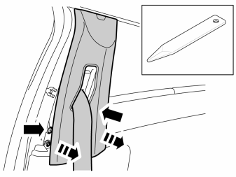
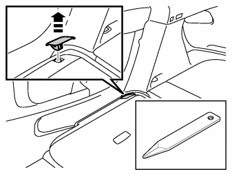
- Detach the B pillar panel at the rear edge by prying the sides using a weatherstrip tool until the two clips release.
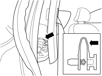
- Unhook the safety clip from the panel.
- Angle out the panel at the lower edge, and unhook it at the upper edge so that the upper clip releases.
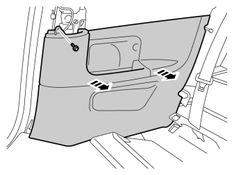
- Remove the screw from the right-hand panel in the rear seat.
- Carefully pull the panel from the body side and unhook it from the sill panel at the front edge. It is secured by eleven clips on the inside.
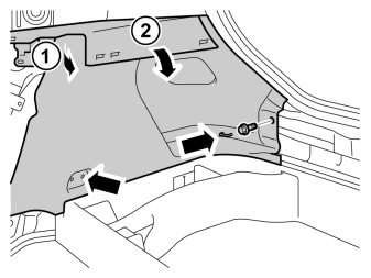
- Remove the clips at the rear edge on the right-hand rear side panel.
- Carefully pull the side panel off, starting at the front edge of the upper edge and then straight back until all clips at the top edge have released.
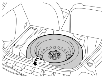
- Fold the panel inwards. Release it from the anchorage eyelets and lift it out of the spare wheel well.
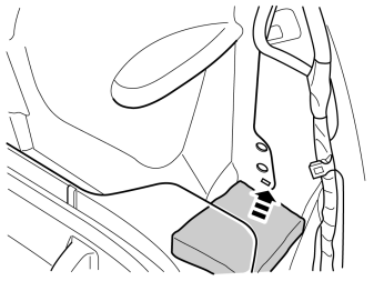
- Remove the square sound insulation.
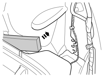
- Remove the sound insulation.
Applies to cars without a trailer module (TRM) and Parking assistance (PAS)
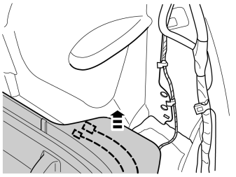
- Locate the grey 2-pin and green 5-pin connector under the corner of the spare wheel well.
- Then pull up the spare wheel well as far as possible for better access.
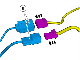
- Connect the adapter wiring to the car's routed cables.
Applies to cars with a trailer module (TRM)
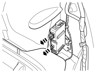
- Disconnect the green 5-pin and grey 2-pin connectors from the control module and connect these to the adapter wiring.
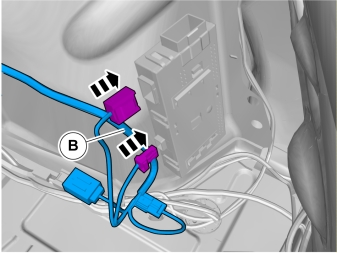
- Connect the adapter wiring to the TRM.
Applies to cars with parking assistance (PAS) without trailer module (TRM)
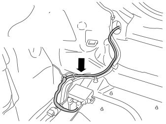
- Locate the 5-pin green connector that is taped onto the parking assistance cable harness. Connect this to the adapter wiring (B).
Примечание: It is important that parking assistance (PAS) is connected the same way as the first unit.
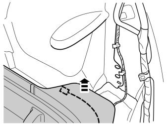
- Locate the grey 2-pin connector under the corner on the spare wheel well.
- Then pull up the spare wheel well as far as possible for better access.
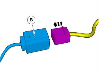
- Connect the adapter wiring to the car's routed grey 2-pin connector.
Applies to all models
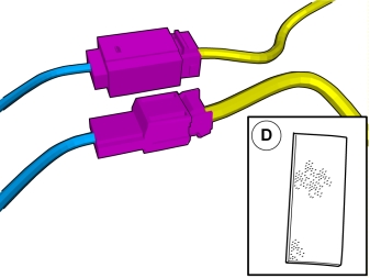
- Apply foam tape to the adapter wiring's connectors.
- Cut off any foam tape excess.
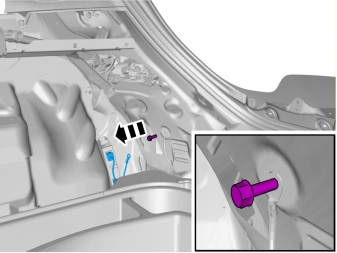
- Remove the screw for the ground terminal under the rear light.
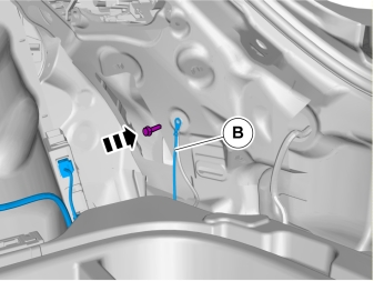
- Connect the ground terminal from the adapter wiring to the ground terminal.
- Tighten the screw. Tightening torque10 Nm (7.3 lbf.ft.).
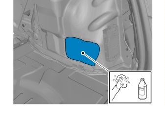
- Clean the marked surface on the body panel using isopropanol and wipe dry.
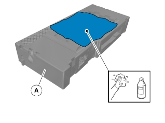
- Clean the marked surface on the control module using isopropanol and wipe dry.
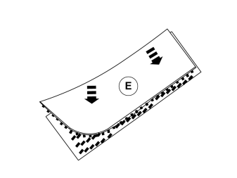
- Take the Velcro pieces from the kit and attach them edge to edge with each other.
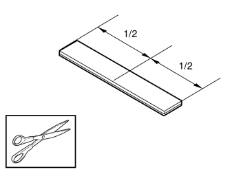
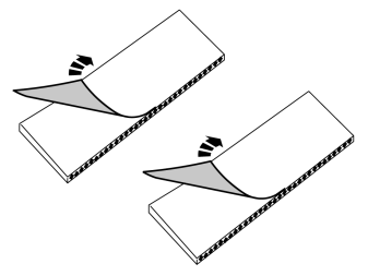
- Remove the protective backing tape from one side of the Velcro pieces.
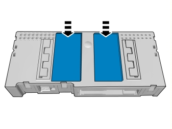
- Secure the Velcro onto the control module properly.
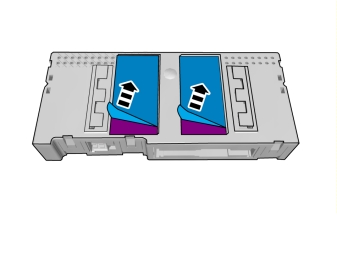
- Remove the protective film.
A and B
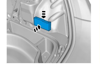
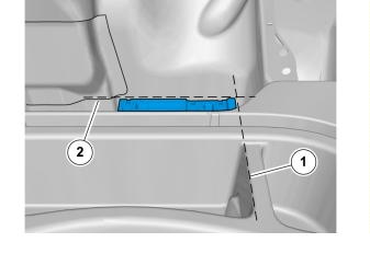
- Position the control module along the rear edge of the rectangular storage compartment in the spare wheel well (dotted line 1).
- Position the control module vertically with the lower panel edge on the wheel housing (dotted line 2).
- Press the control module into place properly.
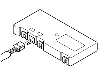
- Plug the 4-pin black connector from adapter wiring (B) into the control module.
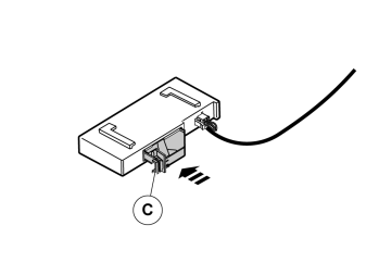
- Install the 50-pin black connector in the control module.
Applies to cars with chassis numbers from 39000->
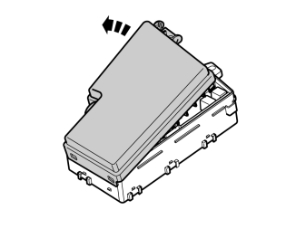
- Pull up the catch on the cover on the fuse box in the engine compartment. Pull up the cover and remove it.
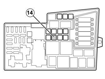
- Take a 40A fuse from the kit and install it in position 14 in the fuse holder.
- Reinstall the cover.

- Reinstall the removed components in reverse order.
- Download the software for the accessory's function following the service information in VIDA.
Обсуждение и оценка
0Пока нет комментариев. Будьте первым.